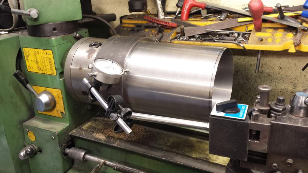
I am so glad that i approached M-Machine-Metals for the material for the smokebox. During discussing the size needed with the metal company we decided between us that they would machine to size including the recessed lip for the door ring but leaving oversize on the stock tube length for me to finish later. The steel tube was 10" overall with the machined area to be about 7" giving me plenty of room for parting off the finished length required of 6 3/16, my machine really wasn't suitable for this work especially boring this large an item.
NB: From what I understood of the material at the time, it stated life as a length of steel tube, 6 1/2" dia and 1/2" wall, having now had this piece of steel for some years it seems clear that it's made from some form of stainless which is perfect for the harsh environment it's involved with.
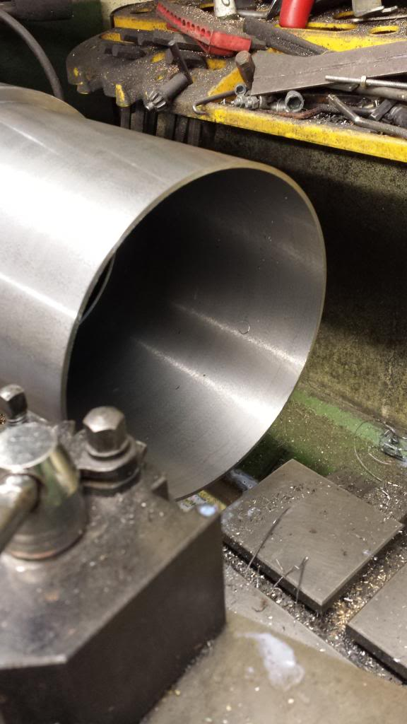
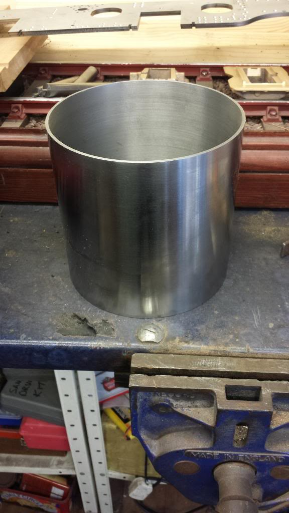
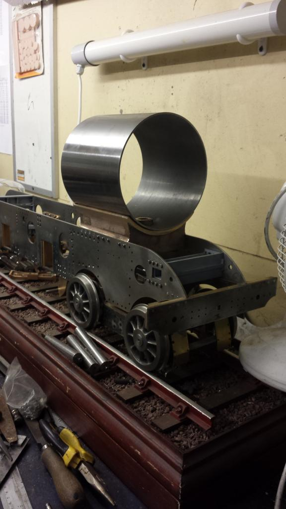
So the job arrived and wasn't quite what I had expected, somewhere during the discussion over requirements the recessed lip that I asked for had got confused and I ended up with a lip as seen in the picture. Not sure how this happened as it was made clear that the recess was for the door ring to fit into? Sizes are correct for the bore, OD and lip ratio just the wrong way around but I guess this is what happens when discussing things over the phone and not supplying a drawing. No big deal, just meant I had a little more work to do and a slight mod required for the door ring.
Did I say simple ?.. it was over-sized in length anyway so that I could hold the tube securely in the chuck without crushing by clamping it by the non-machined section and remove the lip. Thus leaving the face flat for the door ring to fit to later, I left a spigot on the door ring for this purpose, more on this when we reach that stage.. well all I can say is thank god I didn't try and machine the whole piece in my lathe, she's too fast on her slowest setting and the job only just clears the cross slide which also has to have the top slide angled over just to be able to get a tool to touch. However not being one for admitting defeat I did manage to machine the lip off as seen here.
So only one job to do on the lathe and that was to part off to size at 6 3/16".. next time I have something this size that needs machining I'll get someone else to do it, my machine is at it's very limit for something of this diameter and length. I couldn't part it from the front, it was just too big but could part it if positioning the tool on the other side ( more room) and running in reverse. I cut the groove until nearly through and then finished with a hacksaw, reversing in the chuck to finish.Thank God I didn't try to machine the whole job, it just wouldn't have happened. The white tape seen was to reduce chatter.
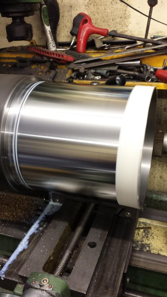
and here we finally have the finished tube,, well that is in as far as size is concerned, I tackled the various holes later..
Now a job that still needed doing to the frames was to cut out the exhaust passage slot that connects the outside cylinders with the saddle that has the cast port passages within it, again, as per prototype. Before i could tackle this job I first needed to machine the saddle casting to fit between the frames and machine it's edges square so that I could line it up to accurately cut the exhaust port openings.
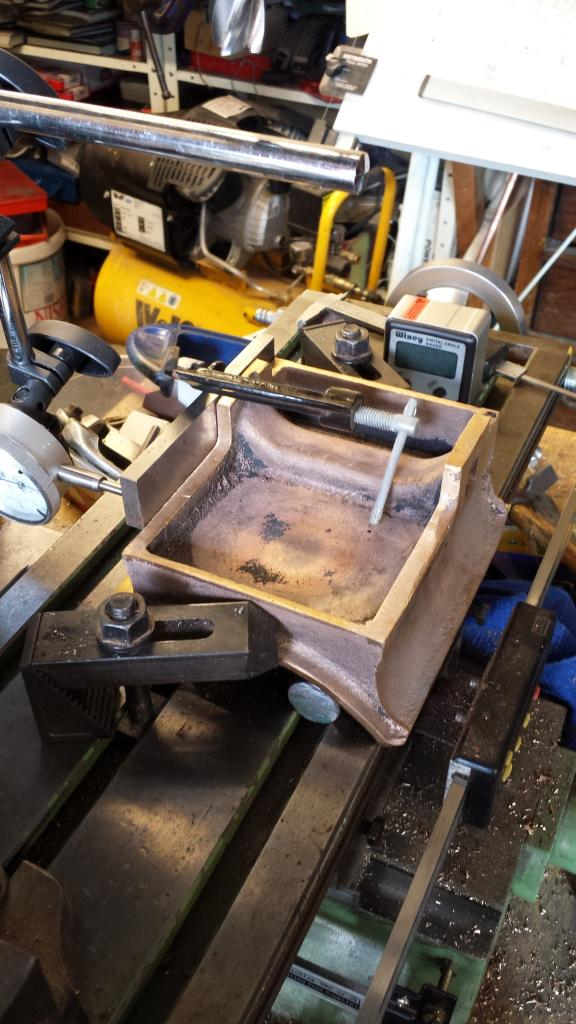
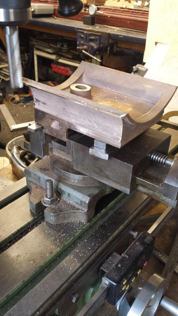
This first picture is to show my chosen setup, I have deviated again from Don's words and music. Don states to fix the saddle to an angle plate, I looked at this but wasn't happy, my reasoning being that I had no good edge for a datum, the casting was rough and out of square although the saddle radius was spot on for the smokebox tube which btw is what Don states in his article needing no more than a light file to remove rough bits.
The rear of the saddle was also reasonably good but the front and sides have large amounts of flash around them making it difficult to be sure that when held on an angle plate that the casting is square with the saddle radius which for me is the most critical part, that is ensuring that the smokebox runs true along the frame centreline.
Instead I chose to sit the casting upside down on two lengths of 3/4" steel bar which in turn sit in two of the bed T slots, this takes care of getting the casting centrally along the X axis, just requiring the casting to be level along Y for which I used the digital angle. Having found it's level, the casting was packed up along one edge to maintain said level and held down via two clamps, tight but not too tightly risking deforming of the saddle. I then clamped a piece of steel flat bar along one edge and clocked it to see how things were going, this gave an error of 2 thou, however when checking the squareness of the front and back edges from the steel bar they were both out but by roughly opposite amounts, slightly more in favour of the side 2 thou out ( hope this all makes sense) So I decided to leave the casting as it was, after all it was sitting centrally along the saddle curve which was what I needed to achieve the most.
Now happy with the set up I began rough cutting the base to size, it's overall width needing to be 4 3/8 which meant around 1/4 to remove overall. This was a lot to take off but perhaps a deliberate move, if you look closely you can see that the exhaust port opening has a flaw along one edge, at first i was worried about this preparing myself for a silver soldering exercise. It's not really a flaw though, looks more like the result of how the casting is poured and hence once machined to size this supposed flaw disappeared.
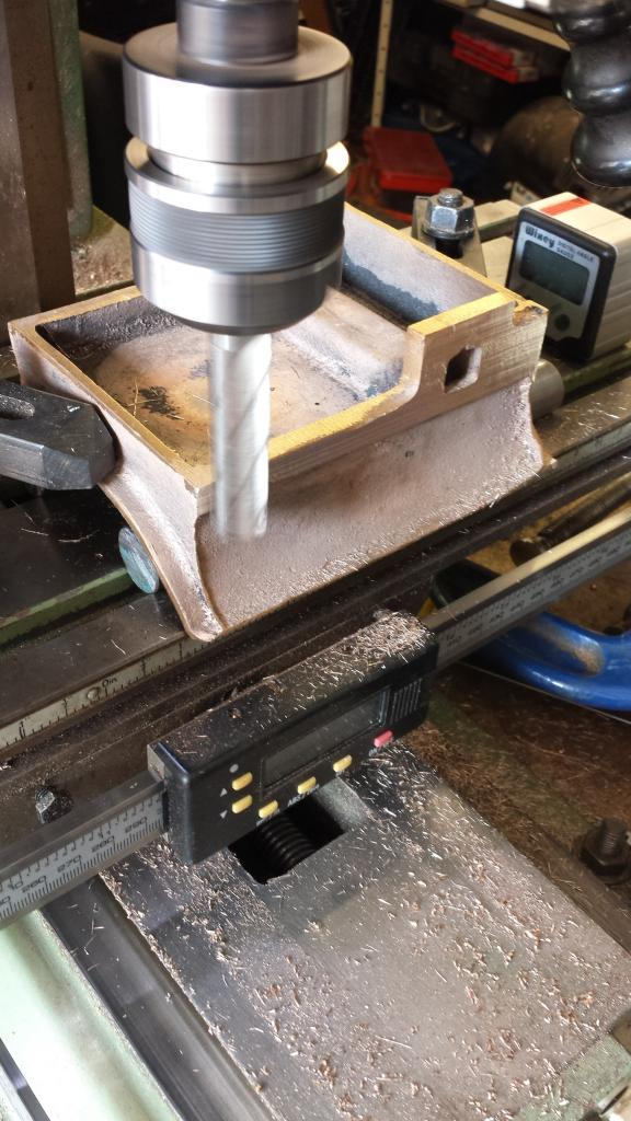
Another reason for the casting width is that it needs to have a 1/8 overhang to sit along the top of the frames, this is cut 1 1/4 from the bottom edge of the exhaust port tabs(top as seen in the picture) and as a check it also needed to be 5/16 from the rest of the saddle base. Here the casting proved to be very good, both measurements were spot on, it was also very reassuring to find that when machined both sides were identical. proving that the saddle was sitting level, always nice to be sure.

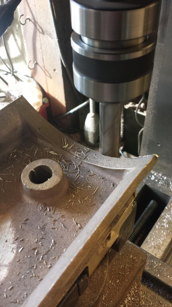
Picture shows one side machined to size, note how the port opening is now a good shape although i haven't filed it yet, I'll also polish/port it to open up the exhaust passageways to make them as free flowing as possible.
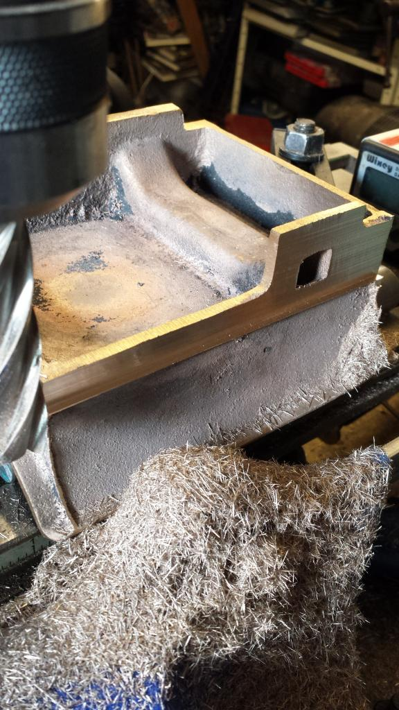
next the casting was up-righted and the side and front edges are machined square removing all of the flash in the process, this as can be seen only just fitted in the machine vice.
with both sides done I had just enough movement on the table to do the front edge, the rear was cast without any flashing so easy to finish with a file, btw both front and rear edges were draw filed to finish, the sides required a different approach later.
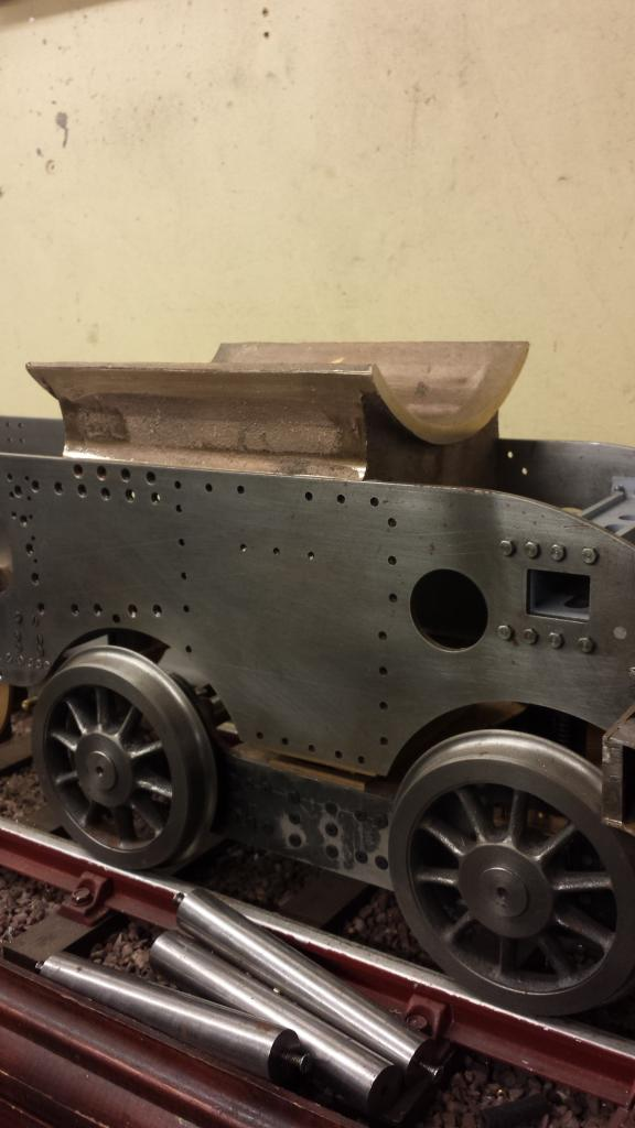
Here we see the saddle sitting in situ, I will drill the mounting holes next before lining up the exact position for the port openings to be cut into the frames, there's a lot of work still to do to the saddle, 56 flange mounting holes, flange needs thinning down and has a number of webs to silver solder on front and back, sides need blending in, flange corners need rounding off etc etc, the list goes on but not required for now, I'll finish it later.
I next drilled and tapped the 18 6 BA holes that take a mixture of CSK screws and small head hex bolts, there's also a few No. 34 holes that are drilled straight through, haven't done these yet here as I wanted to check why these aren't tapped first. A point of interest here is an error on Don's drawing for the frames, one of the no.34 holes is missing from the drawing and yet it's clearly there on the smokebox drawing, something I sorted later
Picture is a close up of the saddle fixing points.
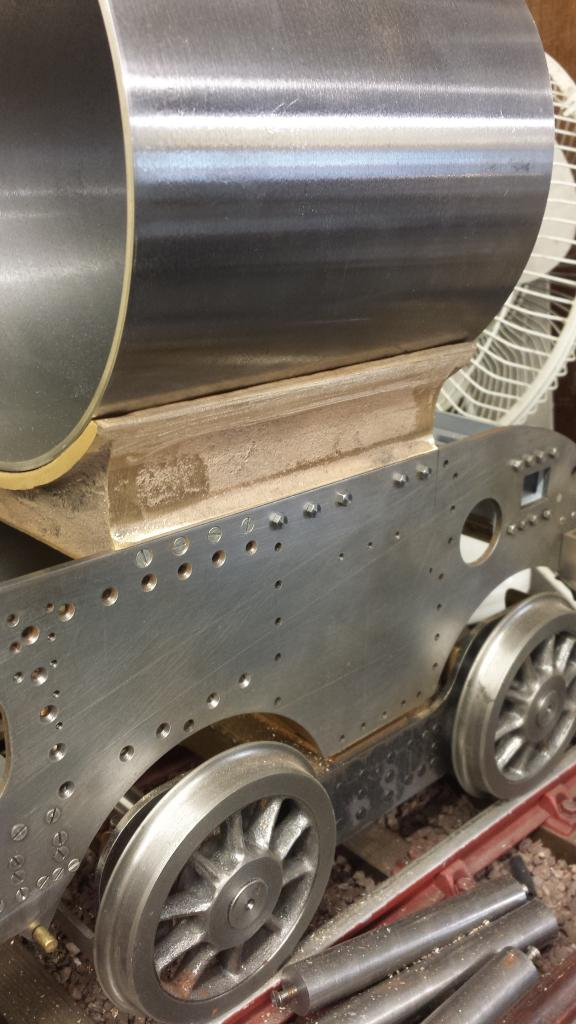
followed by an overall view.. she's slowly taking shape....
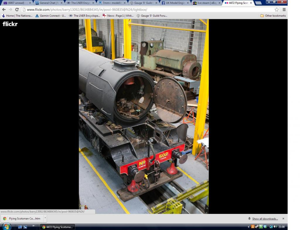
I have drilled and filed ( lot of filing) a temporary hole in the smokebox for the outside cylinders exhaust exit so that the smokebox can sit squarely on the saddle to check the fit. Later I followed full size and opened up the entire lower section of the smokebox so that its sealed along the saddle flange itself.
You can just see the opening in the smokebox shell in this picture of 4472 at York..
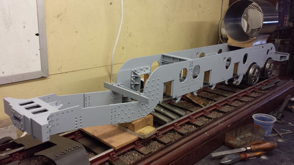
Next job was to plot the exhaust opening in the frames, drill and file to shape and then tidy up the saddle casting, the flange needed thinning down by a fair amount and the rough casting itself needed smoothing out a little too. I had checked the height of the saddle which is as should be for the correct height of the boiler and the saddle's position along the frames was also checked against the GA drawing. One thing that is becoming very obvious is that this chassis is now getting to an uncomfortable weight for me to lift and that's without the front bogie attached yet, no way will I be able to lift it with wheels and cylinders fitted, better start thinking about a building jig....
NB: If only I had realised back then just how heavy this thing was going to get...:)
Well it was one of those days for this stage...I didn't get much of what i had planned to do done. The reason being that spent all day measuring and then remeasuring saddle and boiler position as something wasn't adding up. The reason why will become clear in a minute...so today's question was 'is the saddle in it's correct position'?...well not according to the exhaust opening's as marked it's not. I scrapped all my plans for the day and decided to investigate thoroughly what was going on, first thing was to check the position of the saddle against the drawing and more importantly to me against the prototype. After checking copious numbers of photo's online looking for squared side on views (difficult) Don's GA looked correct. Although, you have to be careful when looking at preserved photos as 4472 was given a new smokebox in the early 80's which is different to the original, one glaring difference which commercial models seem to get wrong is no Gresley Pacific had rivets around the rear of the smokebox tube as seen today. Hatton's new O gauge model being a classic example.
This is the smokebox area on his the GA for Doncaster......following a line down directly from the front of the smokebox it's clear that the front edge lines up nicely with the rear flange of the front bogie wheel, also the measurement from the front of the frames to the front face of the saddle matches up nicely too.
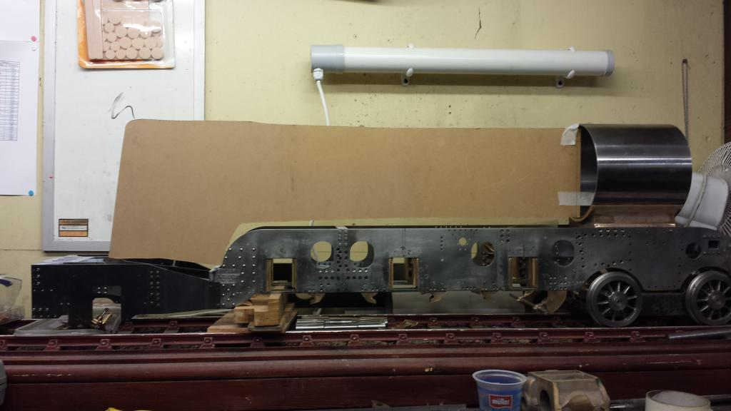
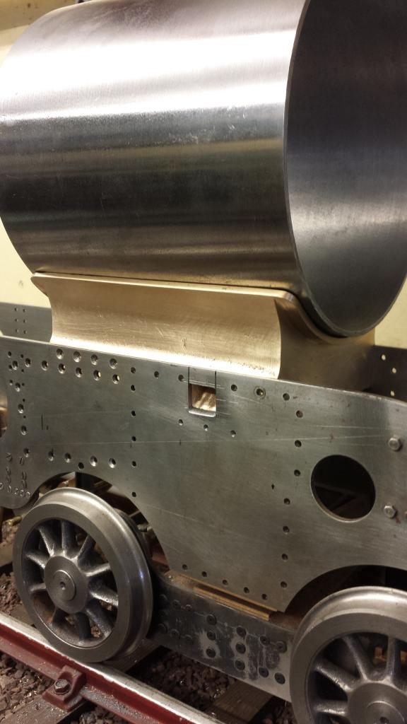
Here's the model with the saddle in the same place as drawing and full size, sorry about the quality but I think it's good enough to see.
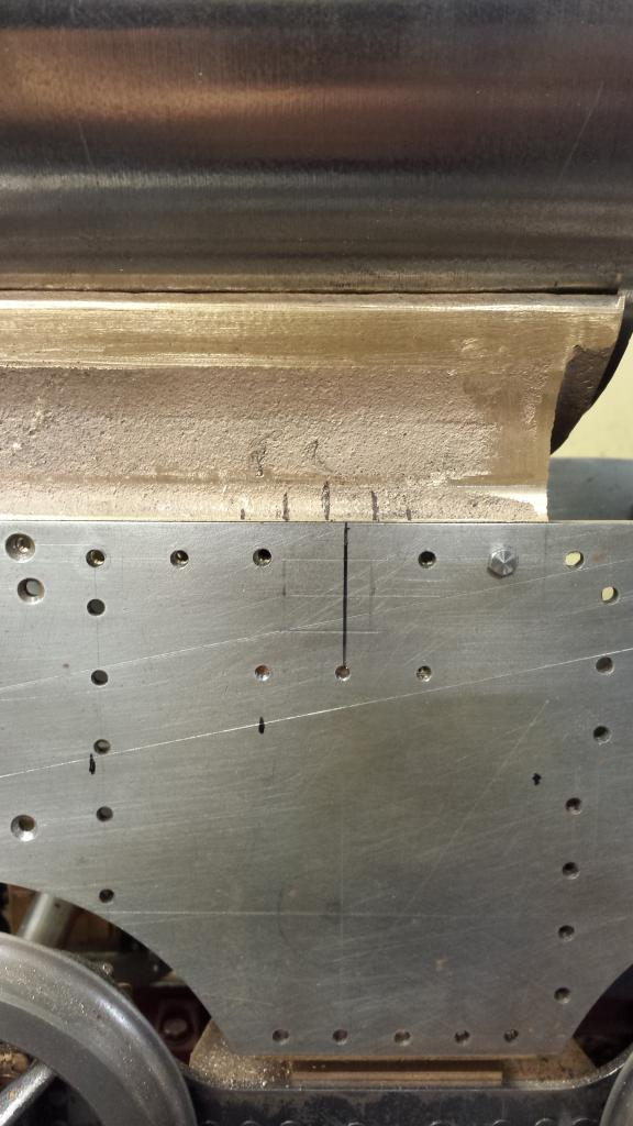
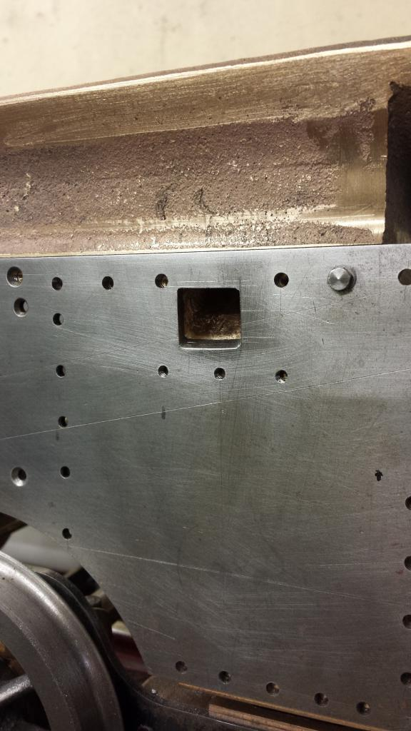
Next a close up showing the marks for lining up the exhaust opening, the long black mark on the frames is where the centre of the opening should be according to the drawings which conveniently lines up with the lower bolt hole. The first line to the left of this line on the casting is the centre of the actual opening with the saddle in this position. I have also ascribed lines for top and bottom and marked the side lines faintly with pen.
I then did lots of checks, took lots of photo's using a boiler template to check if this position worked or if I needed to move it forward the approx 1/8 that it was out, this can be done if needed as it's enough movement to drill new holes. Even though the exhaust casting was saying to move the saddle forward, the fact that it all lined up as per drawing and prototype in it's current position I was hesitant to cut any metal until I knew exactly what was going on, plus if the saddle was moved forward to match up the exhaust as per casting it would be too close to the forward bolt hole for the cylinder flange plate, the hole was clear but not enough for a bolt head to fit .
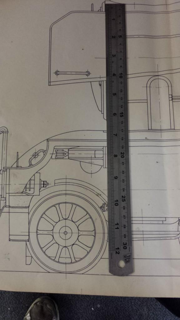
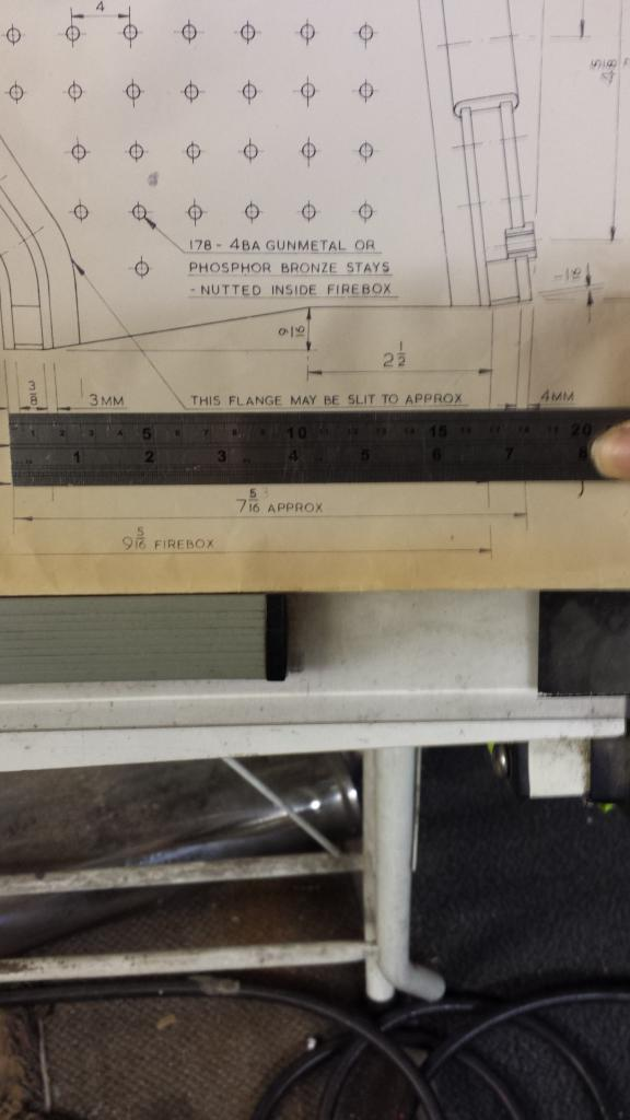
Using the template I checked the boiler fit with the saddle in both positions, neither looked right to me so I rechecked the drawings, the saddle dimensions and the smokebox tube dimentions. Here things began to become a little clearer...first off the saddle and smokebox tube are as God intended so I could breath a sigh of relief. Next to check was the drawing, I had drawn the template as to the measurements given, of course this doesn't include cleading but that wasn't relevant here, one error became obvious along with a mistake on my part in positioning of the template. The error was a simple one which i didn't spot until I placed the template over the drawing but it did help with the boiler's position in regards to overall length, my template was too long by 5/32. I first checked other measurements for scale in case the print was out a little which often happens with drawings. the print was correct as I've found on previous pages so it was time to check the written measurements against a rule. I found that the firebox length of 7 5/16 was wrong, the actual measurement is 7 5/32 as can be seen with the next picture although it is a bit dark, as a double check I checked the the measurement above of 2 1/2 which is spot on confirming the drawing is to scale.
As for my mistake well while lining the template up with the drawing I realised that I had been fitting the template wrongly, I had been butting it up against the smokebox tube forgetting that a portion of the boiler slides into the tube for fixing. Once i had trimmed down the template by 5/32 and fitted it correctly into the smokebox by approx 1/4 everything fitted as shown here.
I did a few more checks, measured back from the drag beam and checked the fit of the firebox crown over the boiler stay and all looked good, perfect in fact but i'm still a little puzzled by the exhaust positioning? I have checked the cylinders and the opening will make no difference here as the cylinder has a very large elongated opening about 3 times longer than in the frames, the cylinder flange that is a separate item will need it's opening moved to match but looks like it will fit between the various mounting holes.
So I spent another few hours checking what's what... Anyway I've convinced myself that I have put the saddle in it's correct position even though the marked position for the exhaust opening's doesn't line up...why this is the case i have no idea but I've decided to just get on with it. Having said that I did check the position of the centre cylinder as from what I can see this is the only item likely to be effected if what I think is the saddle's correct position interfere's with Don's design.
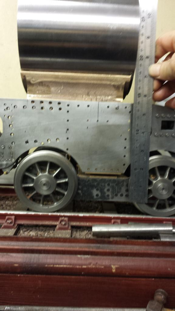
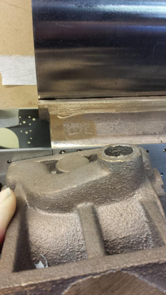
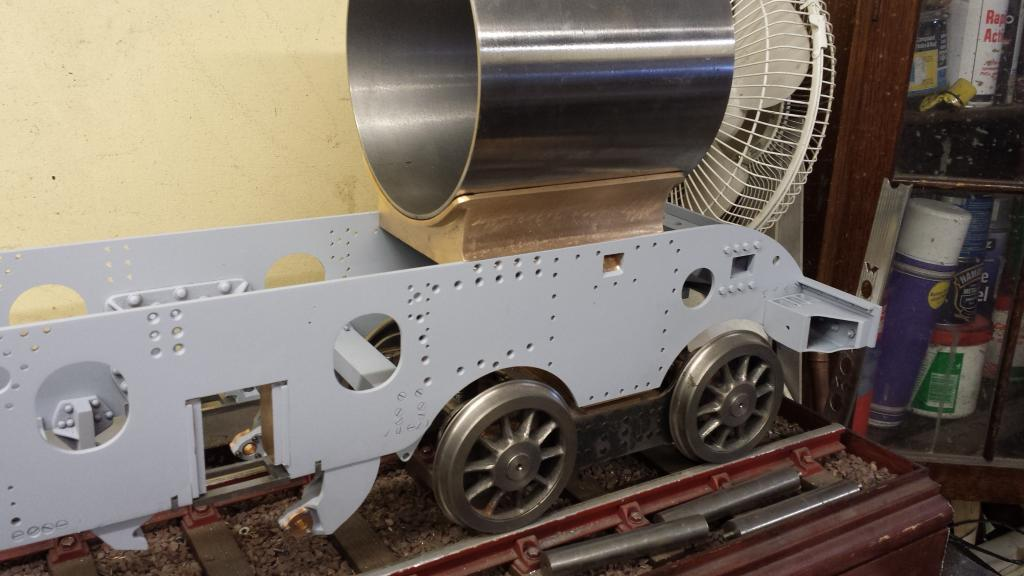
Picture shows me holding the cylinder roughly in position to check that the steam/exhaust openings don't foul the saddle's rear face. As can be seen it's close, but then it is on the drawing, if I moved the saddle forward to match the exhaust positions this would be even closer, perhaps fouling the rear of the saddle with it's 1/8 thickness? All looks good though so I left the saddle as was, I tried to check all possibilities and think way ahead but I had to make a decision and that I now did.
NB: Later, much later I realised where the 1/8 error may have come from, there's a 1/8 difference in mounting position between the two bogie types. Perhaps Don didn't allow for this on his drawing?
Moving on, I bit the bullet and finally cut some metal, only on one side so far but here was the result, I do like Don's design, love how the slot is angled to match the casting, should help in free flow of the exhaust gases. I've cleaned up the inside of the exhaust opening a bit but will do a little more, need to make something up to reach in further as there's a flash line along the upper length of the tube between the two cylinders cylinders that needs removing.
I finished drilling and filing the openings through the frames for the outside cylinder exhaust ports, I also spent a number of hours grinding and filing the saddle down to scale proportions, i took more than half the flange thickness off (compare it to an earlier picture) which is why it took so long and filed smooth the front/back and side faces and rounded off the flange corners. I then drilled through the lower three exhaust port flange holes (oversize for ease of assembly) , it seems that it allows bolts to screw through from the inside as the frames are tapped 6 BA here rather than the saddle. Looking at it this may be to allow easier access to remove the saddle/smokebox otherwise the two outside cylinders and all of the motion would need dismantling first.
NB: Later I changed this and counter sunk the frames and tapped the saddle to accept 5 BA as once fitted the saddle will not be removed unless a complete rebuild is required. I am referring to the 3 holes below the exhaust opening. This hopefully will become clearer later.
The saddle still needed a lot of work but nothing that effected the rest of the frame erecting which was my main aim then, here I had a lot still to do as to date everything done on the frames was very much a rough and ready pre-assembly stage. This could now change as on this day I received my order from EKP for a few hundred 6, 7 and 8 BA x 1/4 screws in both small hex head and csk types, lots of work to do there then.
Next involved a marathon session (i seem to have a lot of those) in stripping everything down, painting with Acid 8 and reassembling with small head bolts for scale. This took many hours but i think the end result speaks for itself.
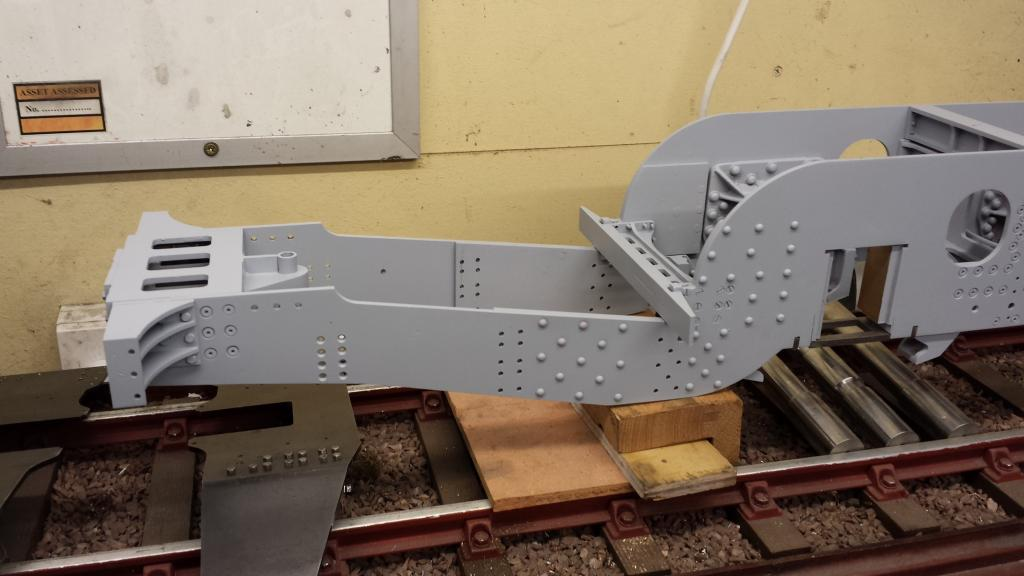
Picture 1 shows the front section.. first job was to disassemble the chassis so that I could finish riveting the spring hangers and brake trunnions in place, I did this one side at a time so as not to disturb the set up too much, once both sides had been riveted and loosely re-assembled the chassis was laid upside down on the mill bed and all bolts/screws were tightened checking that all remained square and true. the main horns were packed tightly with steel bar to ensure that these also were true. At the front the buffer housings were both removed for the fixing of the 4 gussets mentioned in an earlier update. Also the 7 BA screws fixing the housings to the buffer beam were replaced with new ones of a more suitable length, in fact all screws have been changed for the correct length.
Centre section...Same story... spring hangers riveted, bolts/screws replaced, re-assembled and sprayed
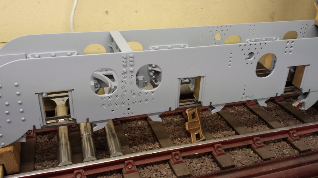
And the rear section.. the trailing frames were currently off in this picture as I wanted to rivet the spring hangers for the cartazzi axle first, I had the four mostly finished hangers from when i did the tender's...all holes are drilled and cut to size, just needed to fit each in turn to the hardened jig, file to shape and machine the recess under each for the shock absorber's to fit into, just as done with the tender.
Finally an overall view to show how she's looking....