
In the last article, we had the reverser ready for brazing but we're not ready for that stage yet. We first need to transfer the mounting holes to the reverser stool which, of course, hasn't yet been made, and then work out the exact position of the stool which will sit in between the main and trailing frames.
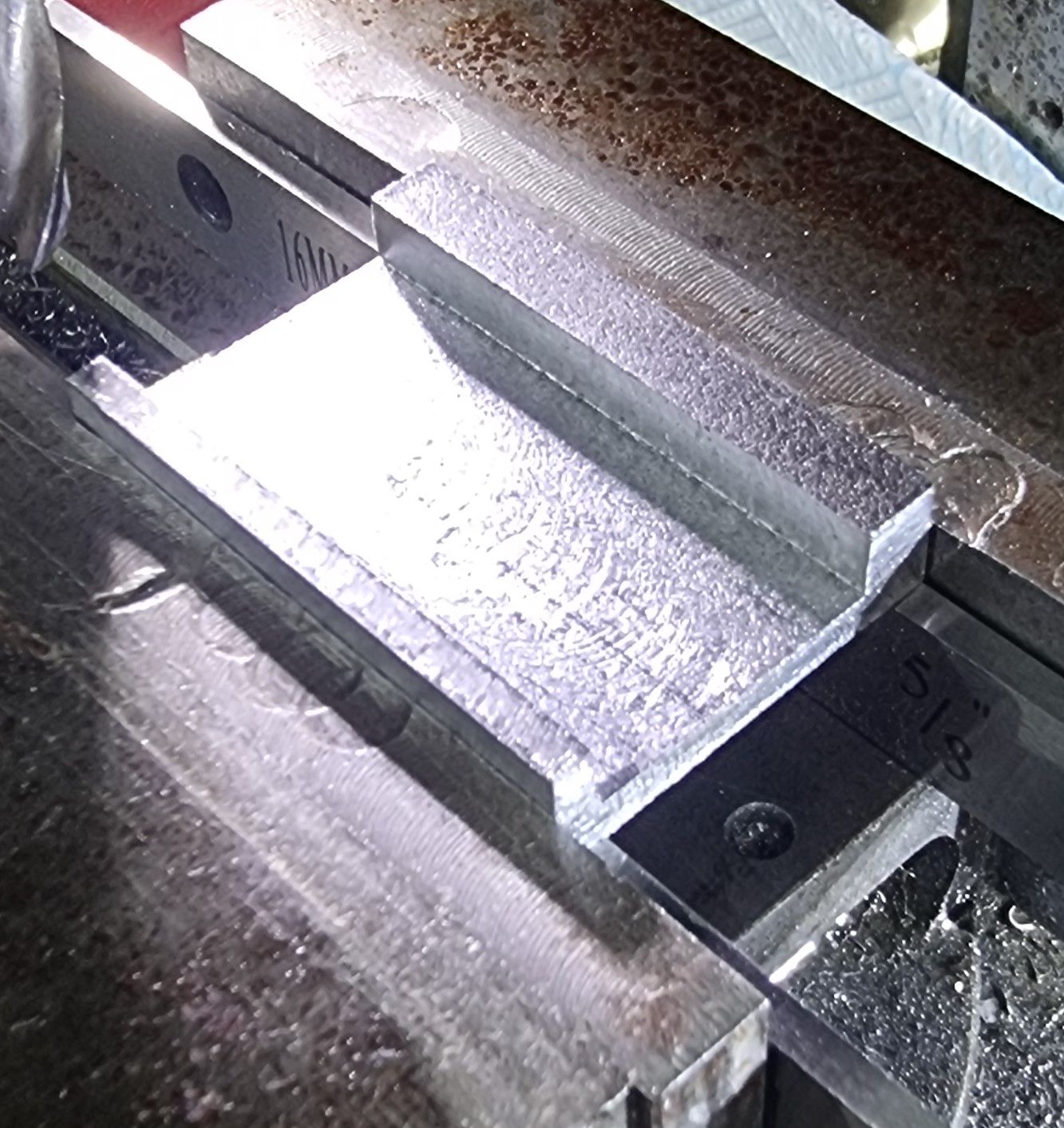
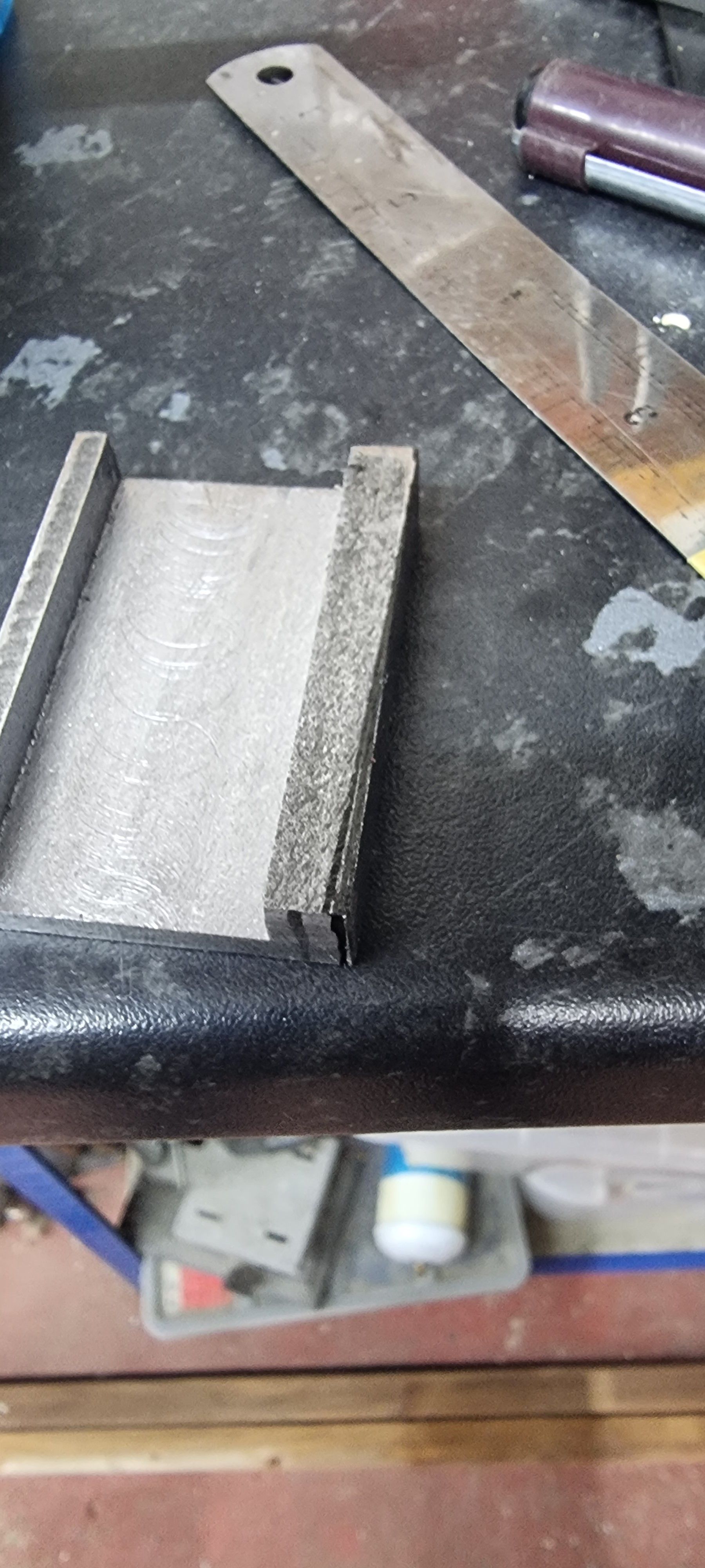
The stool itself is a simple rectangle of 2" x 1 3/8" (made to fit) from a length of 7/16" steel. Not having anything close to that size I machined from the closest size in stock which was 75mm x 50mm x 12mm.. a wee bit of machining required. I used a grinder to get close to size and then machined to size and thickness, not a five-minute job. With the stool machined/squared to size, the next stage was to machine a channel into the underside creating a U channel. Don states to machine a channel leaving 1/8" on the side to the trailing frame and a little wider on the other side to give enough metal to tap into once this side has been tapered to match the main frame. The next picture shows this.
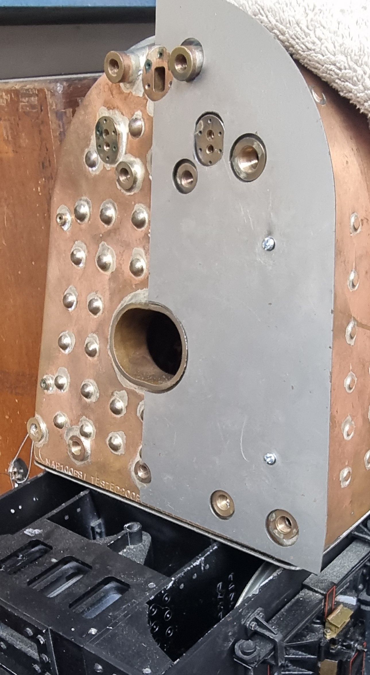
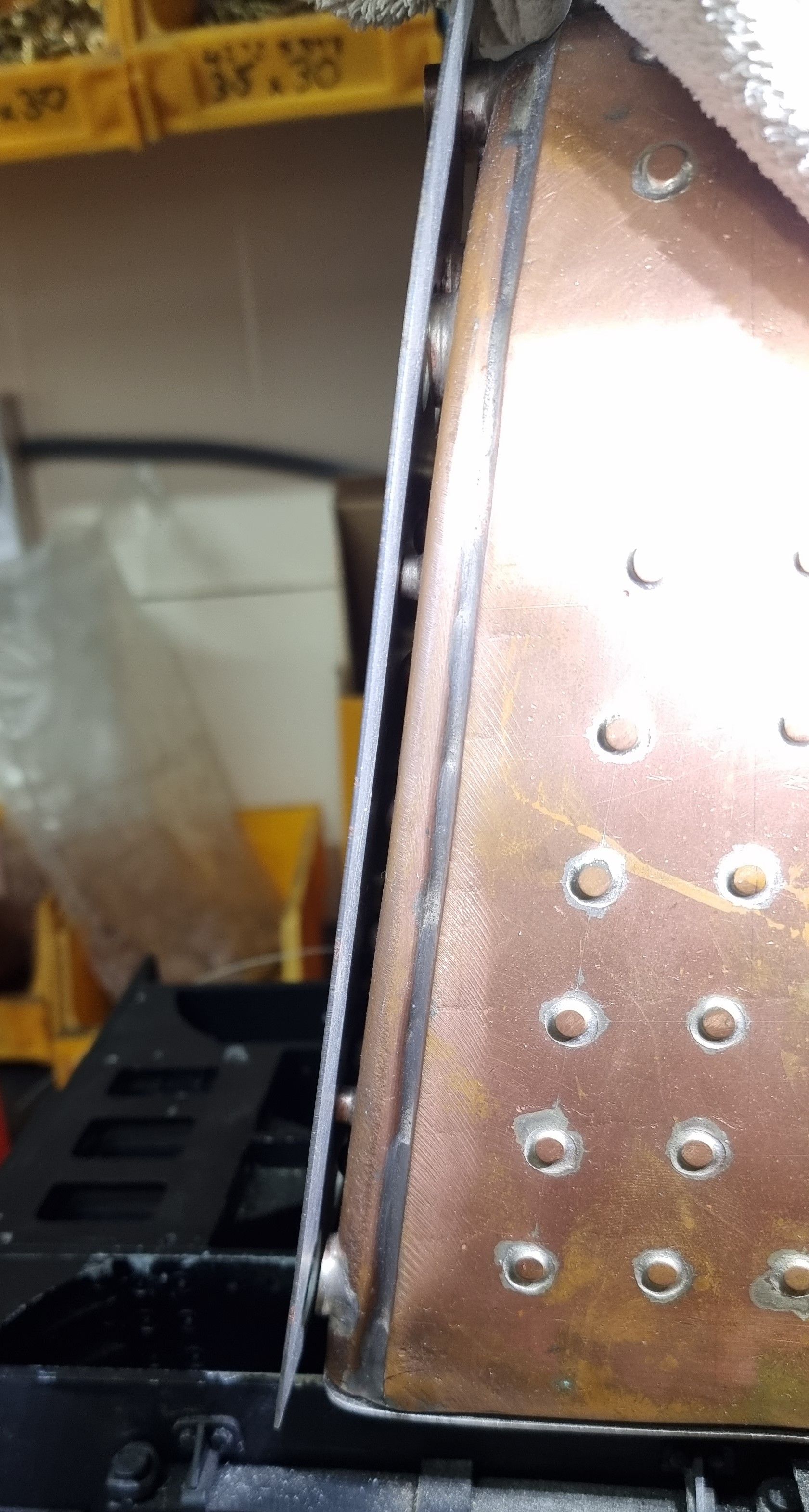
To work out the taper I first needed to take into account the reverser's relative distance back from the backhead to allow for heat expansion, Don advises to allow for 5/32", before I can do this I needed to place the backhead roughly in position. The backhead sections were cut from steel by Ed (Model Engineers Laser) some time ago, at the time I thought the plotted holes might need moving but now that I've had time to look at this more closely they just needed a little fettling to fit. The next picture shows one-half of the backhead temporally held using two 3 mm screws into the mounting bushes kindly fitted by Paul (Southern Boilers LTD), I only need to fit the side of the reverser for now. Note that the two tapped bushes at the bottom will be fitted with blanking plugs with the corner bush being fitted with a washout plug for boiler cleaning. The outside edge will of course be formed to curve around the outer edge of the backhead.
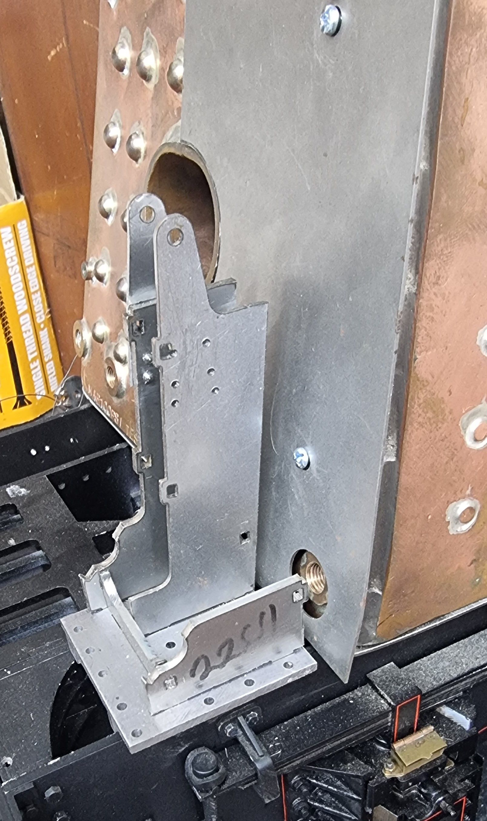
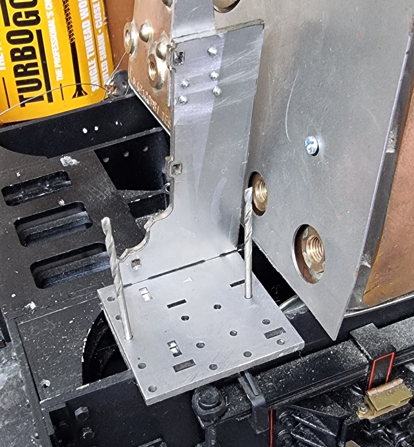
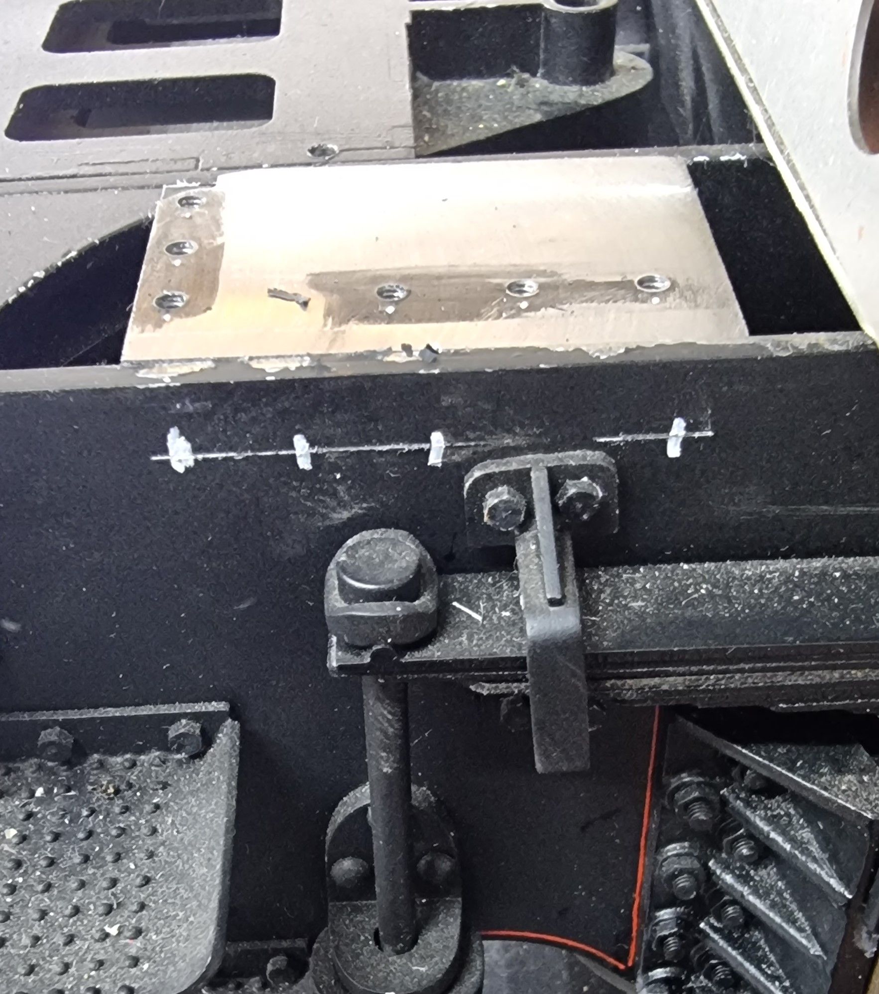
With the backhead positioned, I could then place the stool roughly in place and sit the reverser on top, I had left drilling the mounting holes into the stool until this stage just in case I had missed anything (I did, details in this update), I can now see that I can drill said holes ready for mounting the reverser (once brazed), more on that later. Here I have rested the stool with its finished edge up against the inner trailing frame edge allowing the 5/32 (4mm)gap between the reverser and boiler.

With the reverser in place, I could see/judge the taper required on the main frame edge, as can be seen here, it's not a lot. I also noted that I need to either remove a little from the frame stiffener or the stool, I'll opt for the stool.
I then marked the edge that requires tapering, the plan being to first achieve the correct taper and then remove metal until the stool fits between the frames. As you can see there's not much to remove and thus I did so with a hand file.
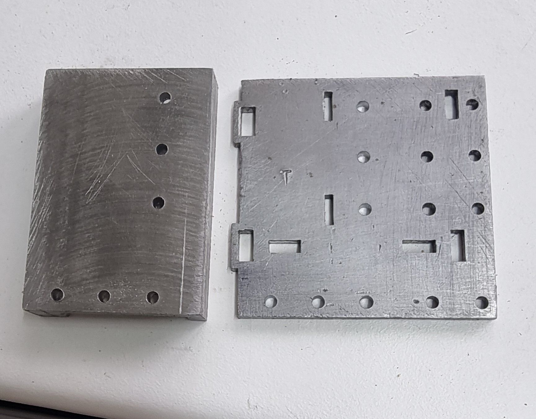
I then needed to transfer the reverser mounting plate holes to the stool, to do this I held the stool in the machine vice along with the mounting plate sitting on top, I drilled the first hole from this plotted at zero, and then the rest using the DRO.
Here we can see the 6 holes now transferred, note that these are at N0.42 tapping size for 6BA with the mounting plate holes requiring to be drilled out for clearance NO 34. later.
It was now time to decide on the reverser's final position while checking for Don's suggested expansion allowance gap. I also needed to be mindful that the backhead cleading will have some insulation sandwiched between it and the boiler. As the next picture shows, there's not a lot of room so have left the cleading mounting bushes as supplied which gives just enough room to clear the copper stay heads and allowance for some insulation material.
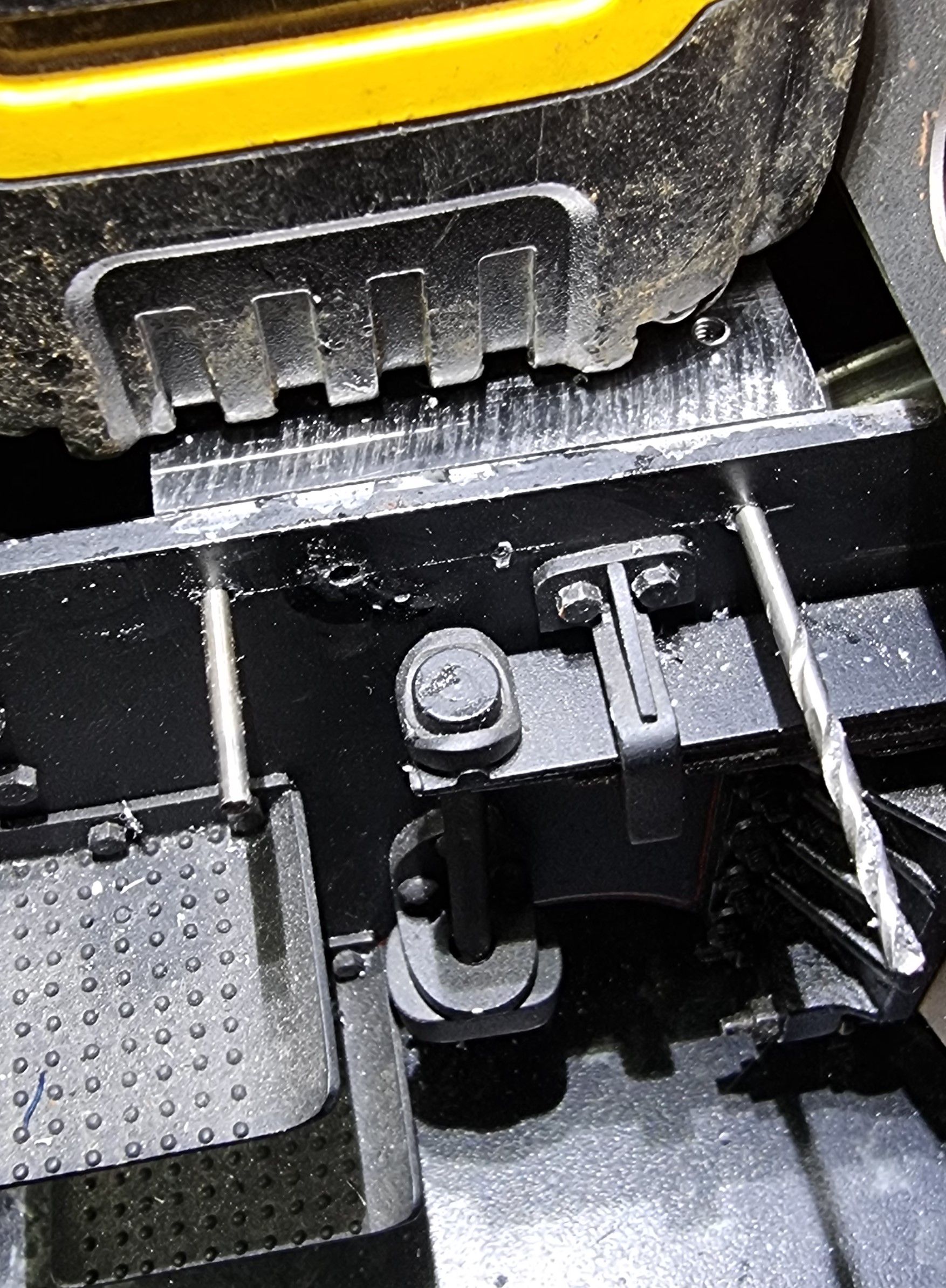
As mentioned I filed the taper by hand and checked for fit, the drawing shows that two of the mounting holes into the mainframes are shared with the drag box stiffener, I am not going to use these as fitting them would be more than a little problematic, I have also shaped the rear of the stool to clear said stiffener.
With the stool in position, I placed the reverser on it using a couple of No.42 drills to hold it in place while I checked the gap, the gap here is just under 5mm so a little larger than Don stated.
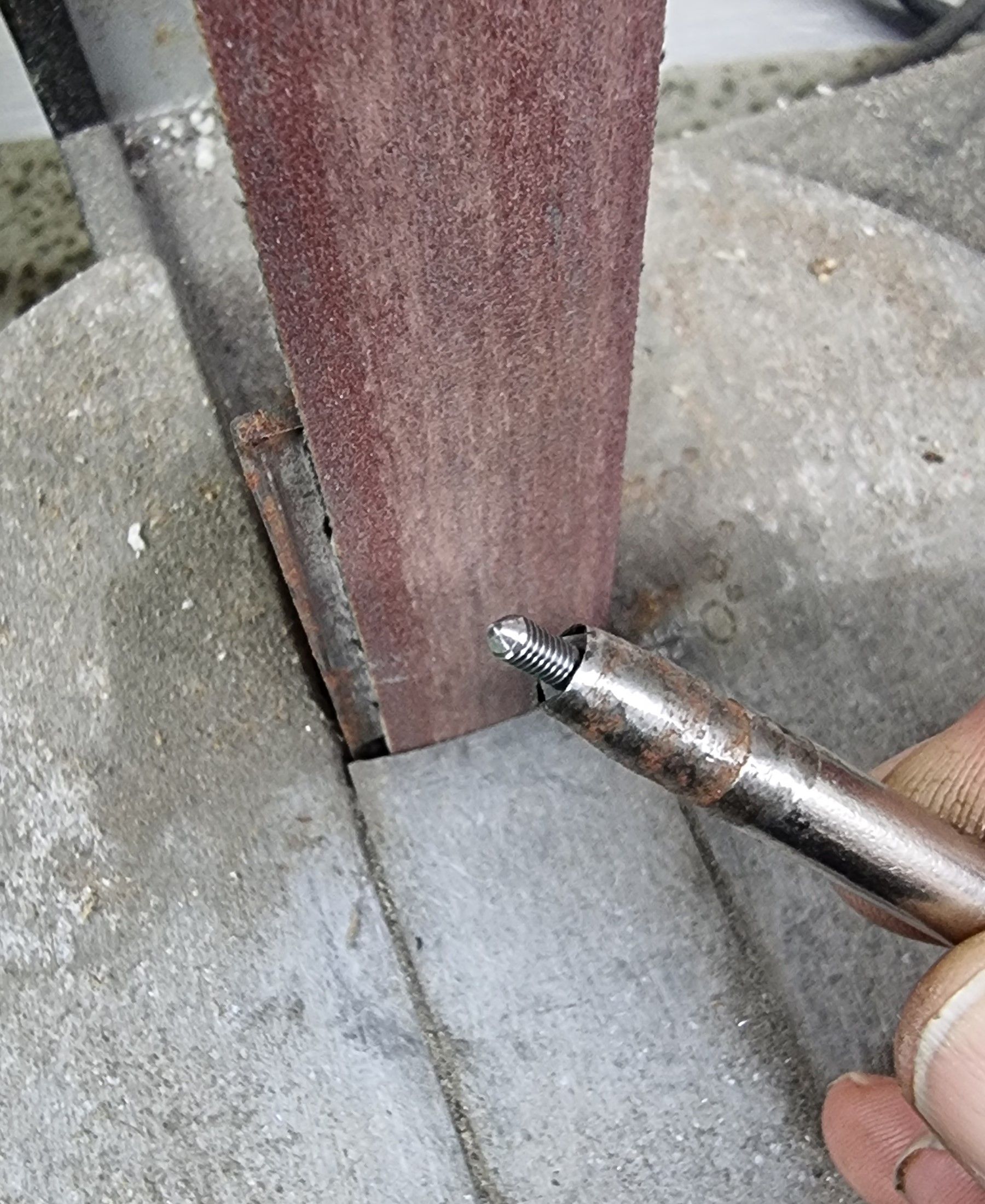
To transfer the inner bolt holes I first marked the holes with a fine point pen (not easy to reach this area, thus transferring holes in the normal way is not possible) and then set the stool up to use the DRO for drilling the holes to match those in the mainframes. With the holes drilled and tapped I made life a little easier by putting a point on the 6BA bolts as shown in this next picture.
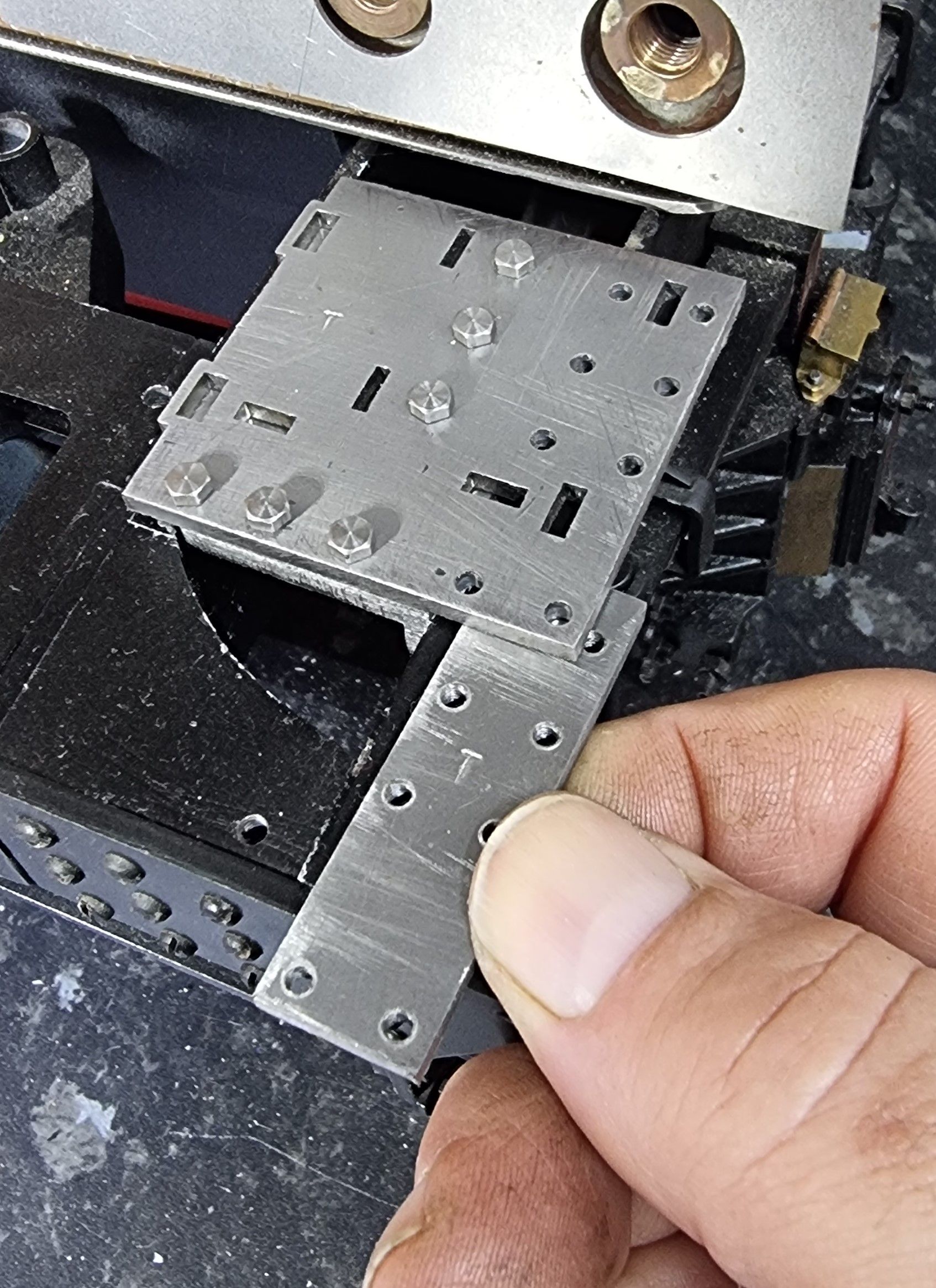
Here we see the 3 bolts fitted tightly and ready for marking/drilling the outside mounting bolts.
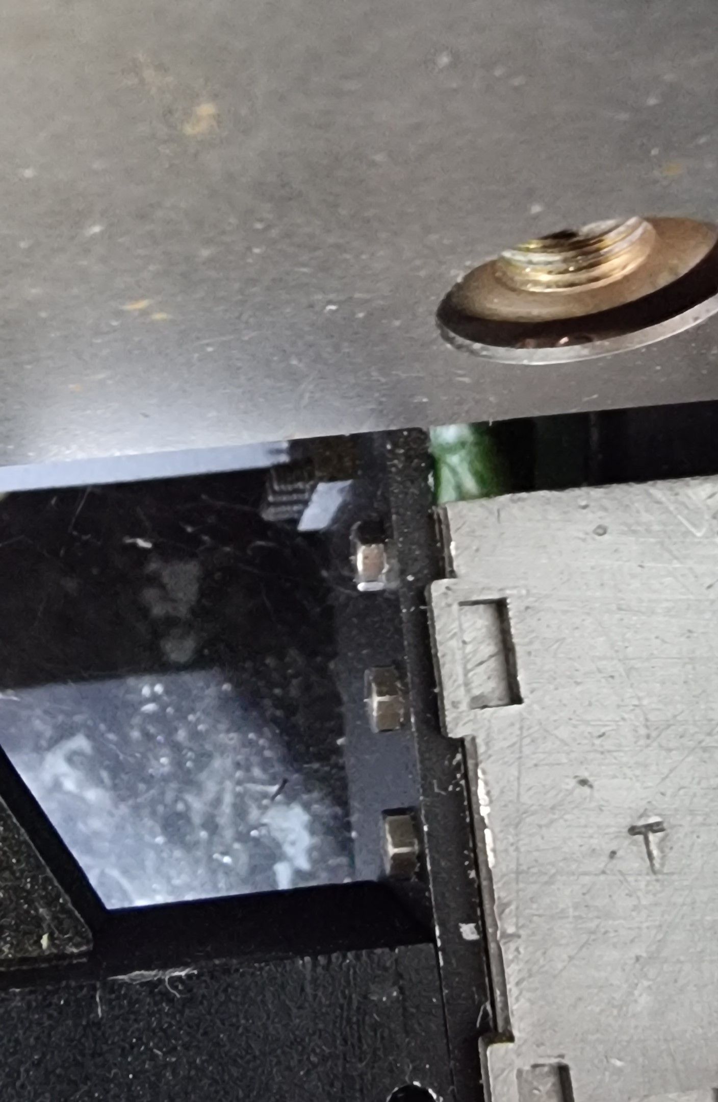
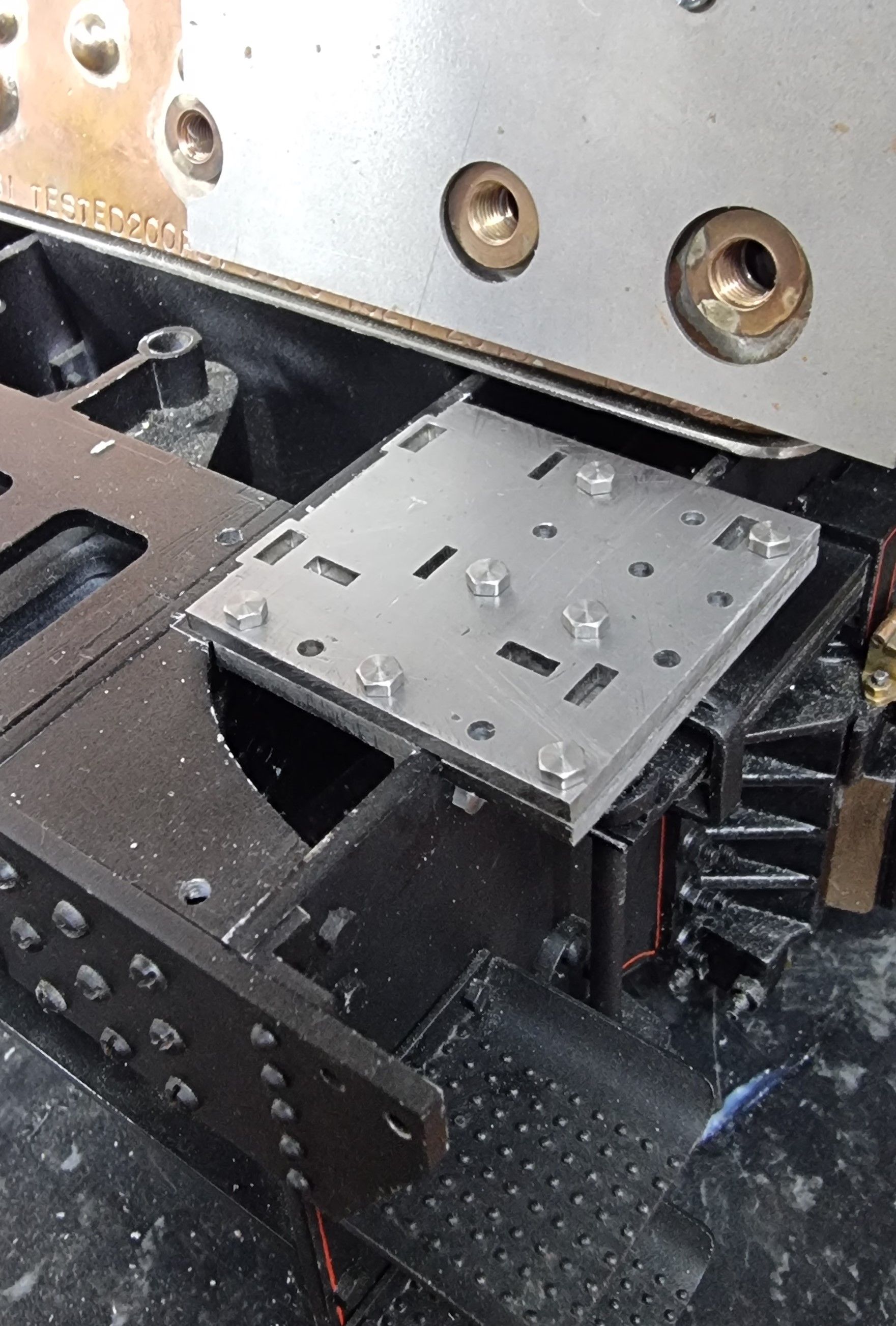
To keep everything flat for the holes to be transferred/drilled I bolted the reverser base to the stool ready for marking out the holes, it was here that I discovered an error that I had made when fitting the reverser base to the stool. I had placed the base directly on the stool but actually, it's offset to the outside, I only noticed when checking the fit with the base doubler bolted to its base. No big deal I just needed to redrill/tap the offending holes but an annoying delay nonetheless. The picture with the doubler plate held shows the problem, there needs to be a gap matching the thickness of the frames.
Before taking the base off I first transferred where the holes should be and then marked the frames down from the top edge 9/32 for where the outside holes need to be drilled. I chose to mark where the holes would best be avoiding the spring guards which Don left off his drawings.
I hate drilling into painted parts but if needs be, I'll have some tidying up to do later. After drilling a hole I placed a spare drill to keep things in place while drilling by hand.
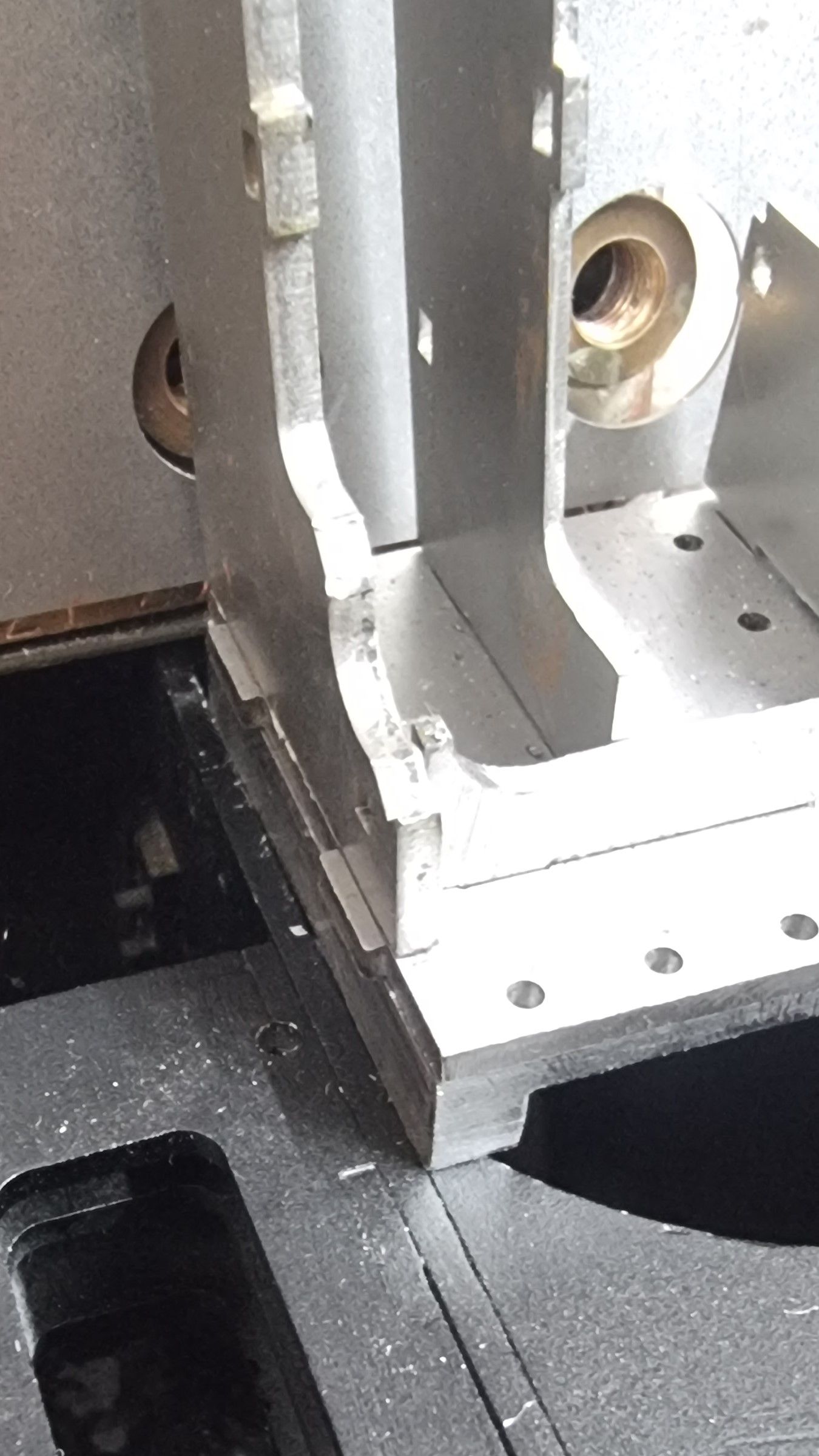
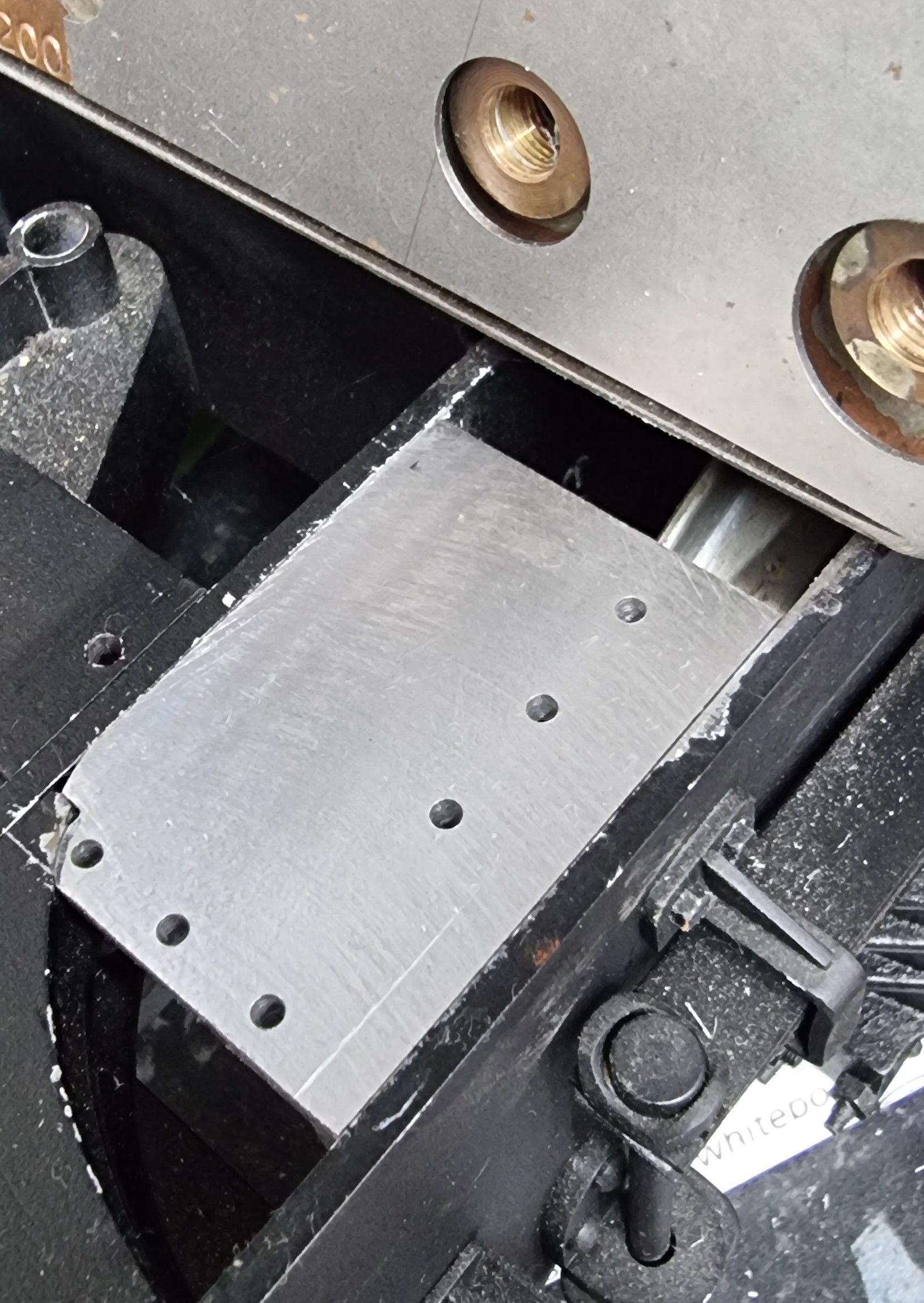
Lastly for this update, we see the reverser base on its stool which is securely mounted and sandwiched between the mainframes and trailing frames.
Next time I'll take a look at the cab floor fitting and then the final assembly and brazing up of the reverser stand.