

Yes, I'm back on the loco, It's hard to believe that the last time I worked on the loco itself was June 2022. The workshop still has some way to go but internally I have half of it powered and it's warm with a new Infrared heater, good enough to continue with the main project while outside is a bit wet and cold.
The Reverser on a Gresley Pacific is a fairly involved component and thus will take a number of parts to cover it in detail. Don's drawing is really good, very close to the prototype needing just a few details added to complete the picture. For those who are on the same road as myself, we are lucky to have plenty of very good photos freely available on the A4 60007 Sir Nigel Gresley overhaul blog.
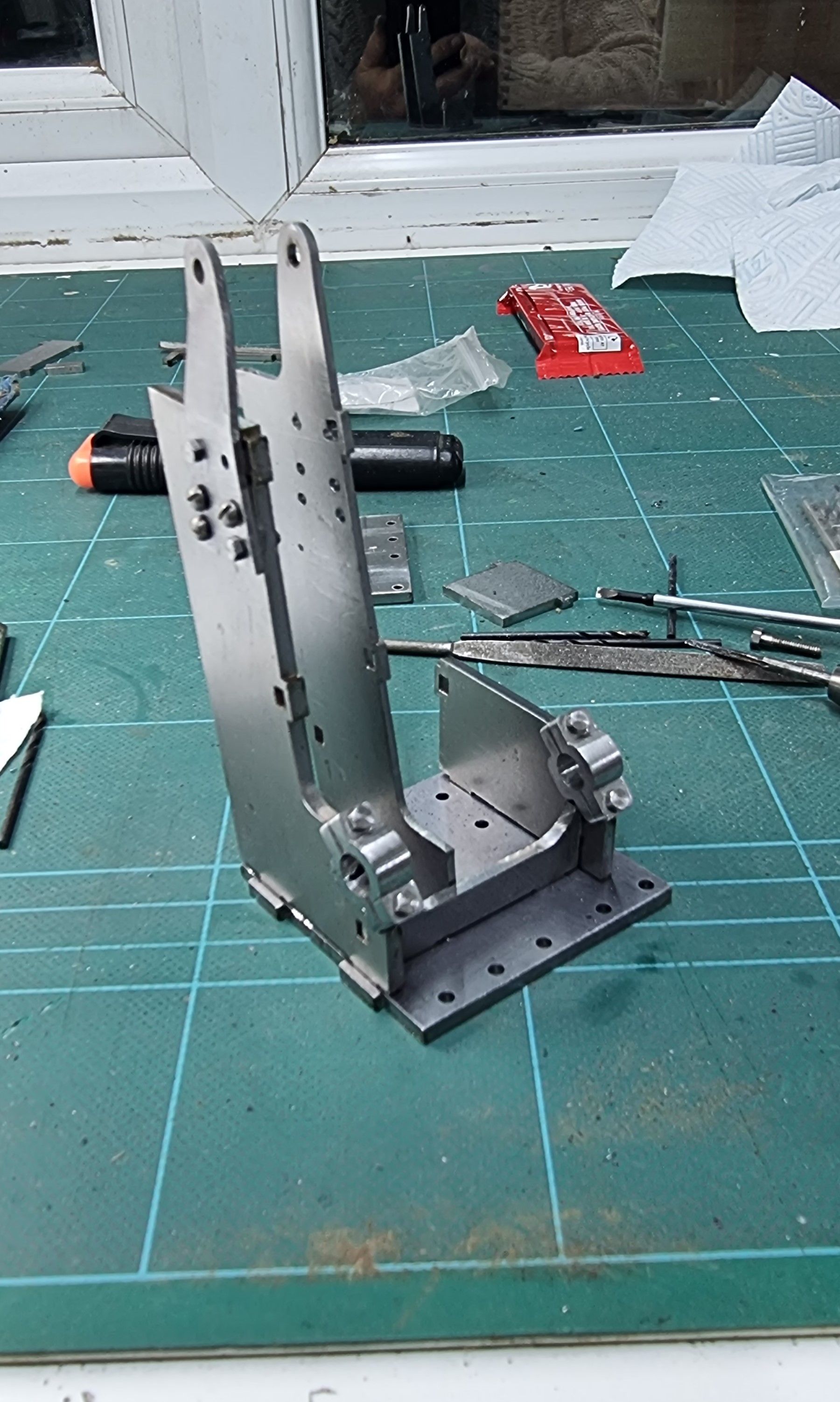
This is a particularly good image showing the general stand, there are plenty of others that will help greatly during the build of this part
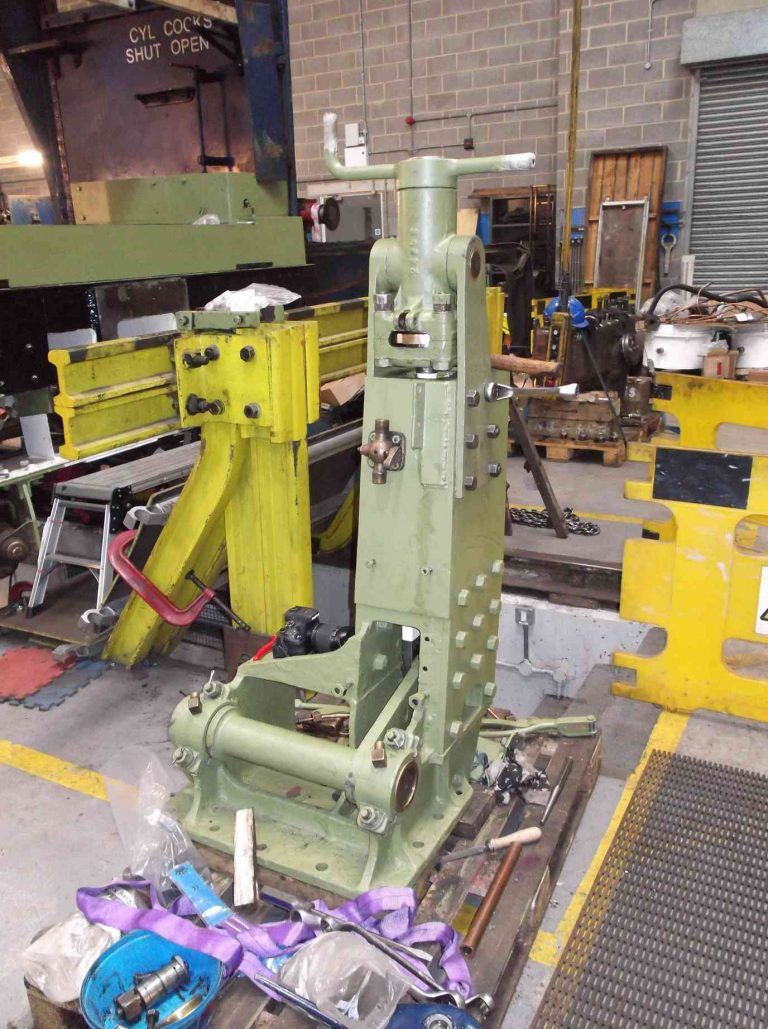
The sanding valve seen on the front of the stand is covered in Don's words (no drawing) but there is another oil cup that sits below this that feeds the two bearing caps below via copper tubes, these will be added later.
Before I forget, I should point out that we are looking at a L/H reverser, of course, I need a R/H version for my A1. The two are identical being just a mirrored image of each other, Don's drawing is for a R/H engine as shown here.
As can be seen, Don's is a very close version, there is one discrepancy ( other than a few small profile differences) in that Don's drawing suggests a vertical plate to the rear on the right side, just behind ( above as viewed) the bank of 6 holes. Compare this to the photo and you can see that Don has left off the platform with supporting web which is seen on 60007. In my mind, he may have done this for two reasons, first to add some strength to the outside bearing plate, and second, with the shelf plate fitted it would be difficult if not impossible to access the 6 mounting bolts below. In Baldric's words, I have a cunning plan to fit the shelf and still be able to reach the bolts below, more on this later.
Enough of the background, on to the model, as with many arts on my model I have used laser cut parts to save time, thanks again to John Baguley for doing the CAD work and Ed Parrott of Model Engineers Laser for doing the cutting. There will be more pictures than usual as it's easier to understand my process.
Below we see the parts as supplied by Ed.
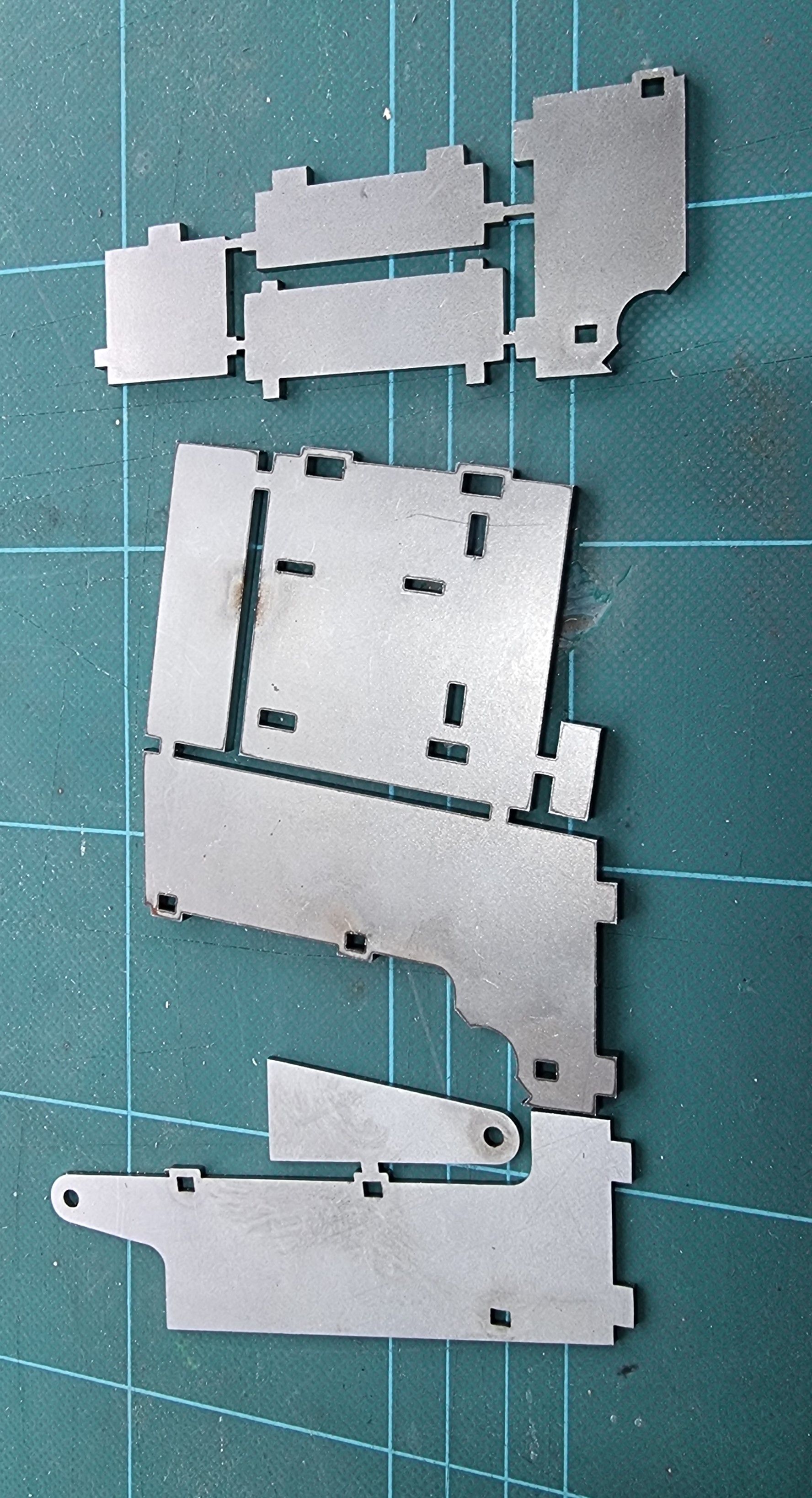
A quick dry run to check the fit
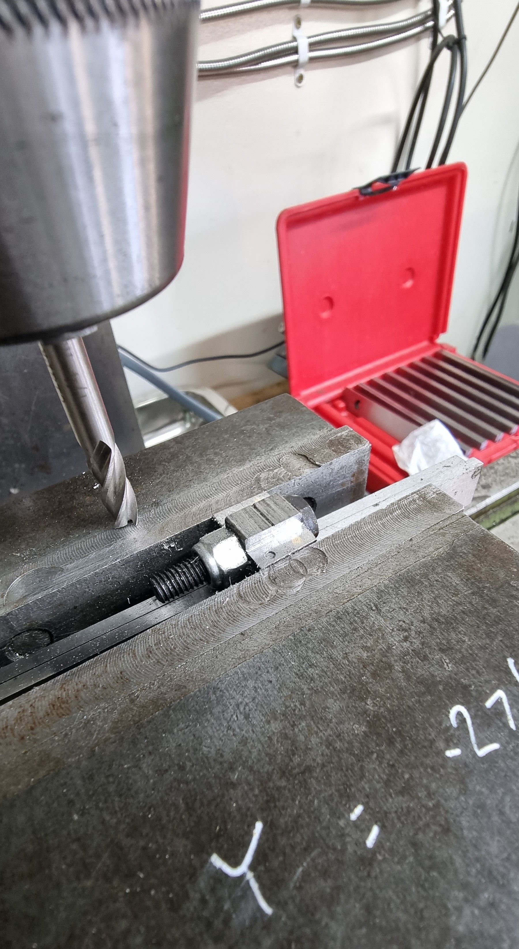
The first job was to drill the holes in the base plate, this needs to be done before barzing together.
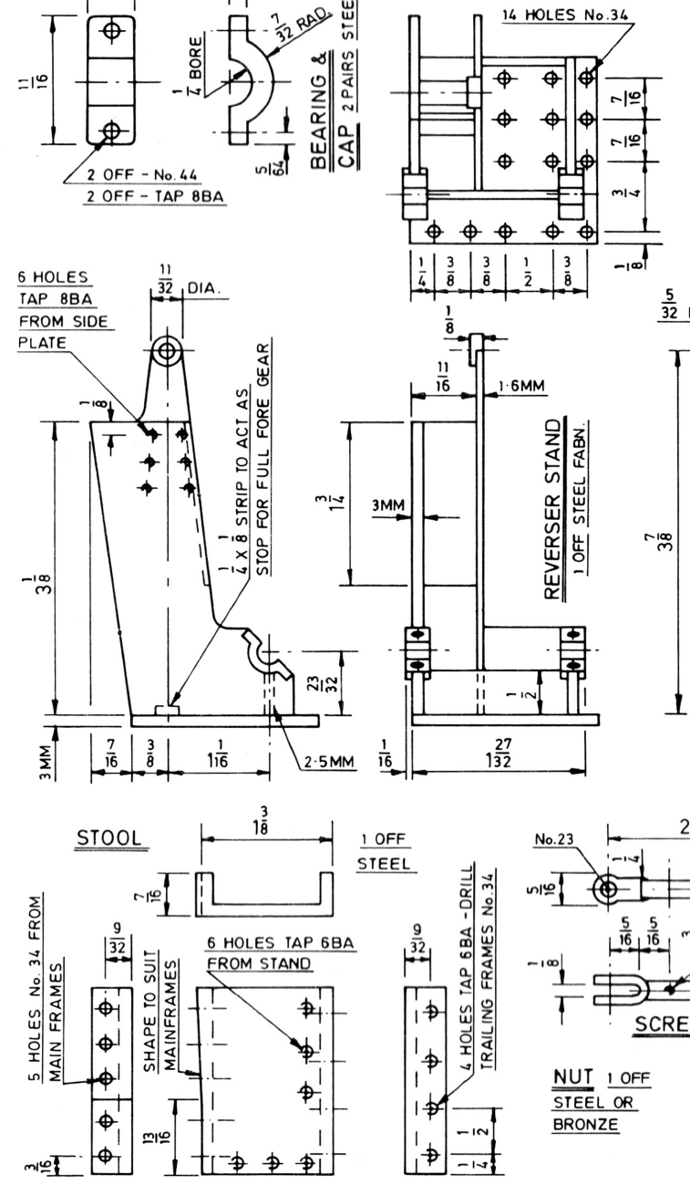
next job was to make the bearing caps which will eventually be silver soldered in place. I first made 4x 3/4 lengths of 1/4 sq bar, these were overlength to begin with, and then drilled 1.8mm ready for tapping 8BA into the bottom halves fitted to the stand, the top halves then being opened up for clearance. You will see the relevant dimensions in the drawing above.
The parts were then bolted together and equaled in length ready for drilling the 1/4" bore down the middle of the bearing block. Normal practice perhaps for this is to clock the parts in the 4 jaw and bore them on the lathe, I chose to do the job on the mill, it's a quicker setup, and for this particular job more than accurate enough.
Drilled and reamed 1/4"
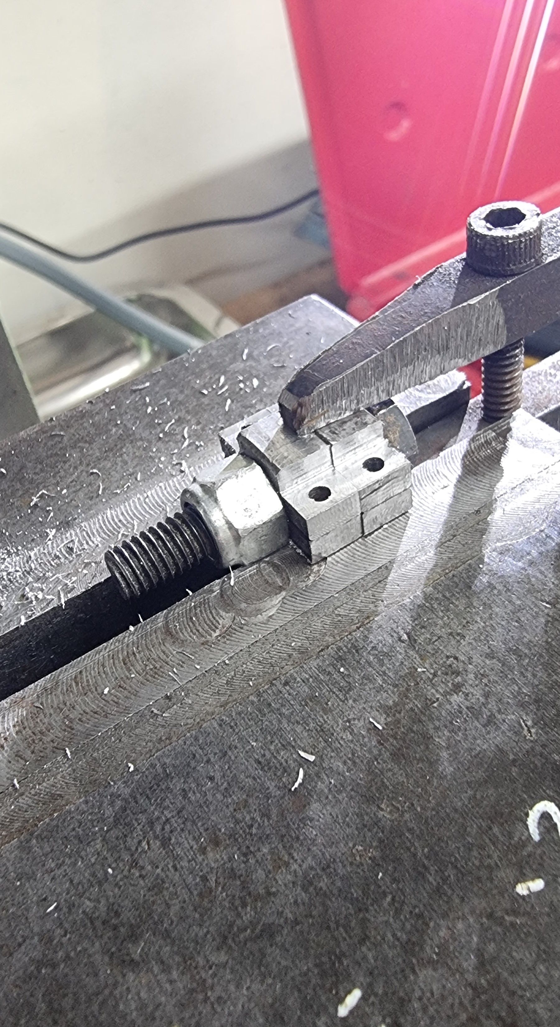
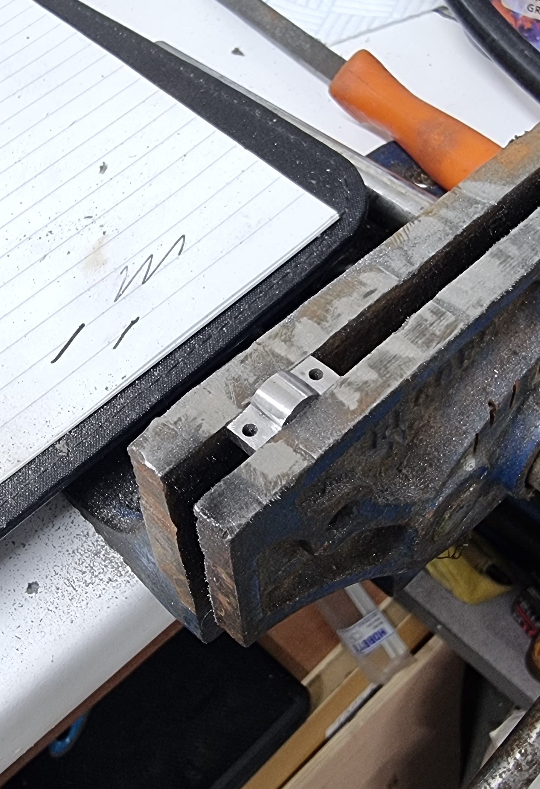
I then needed to profile the blocs to shape, first I bolted the two assemblies together and held them securely on a pair of parallels in the machine vice. The bolts and the jaws gave enough support to machine the first of the block tabs down.
for the other side, I added a small tool clamp (needed a little ground off) and this time sat the blocks on top of the jaws to finish the machining.
It was then over to the trusty files for a little hand work, the final job involving a Dremel sanding drum to polish.
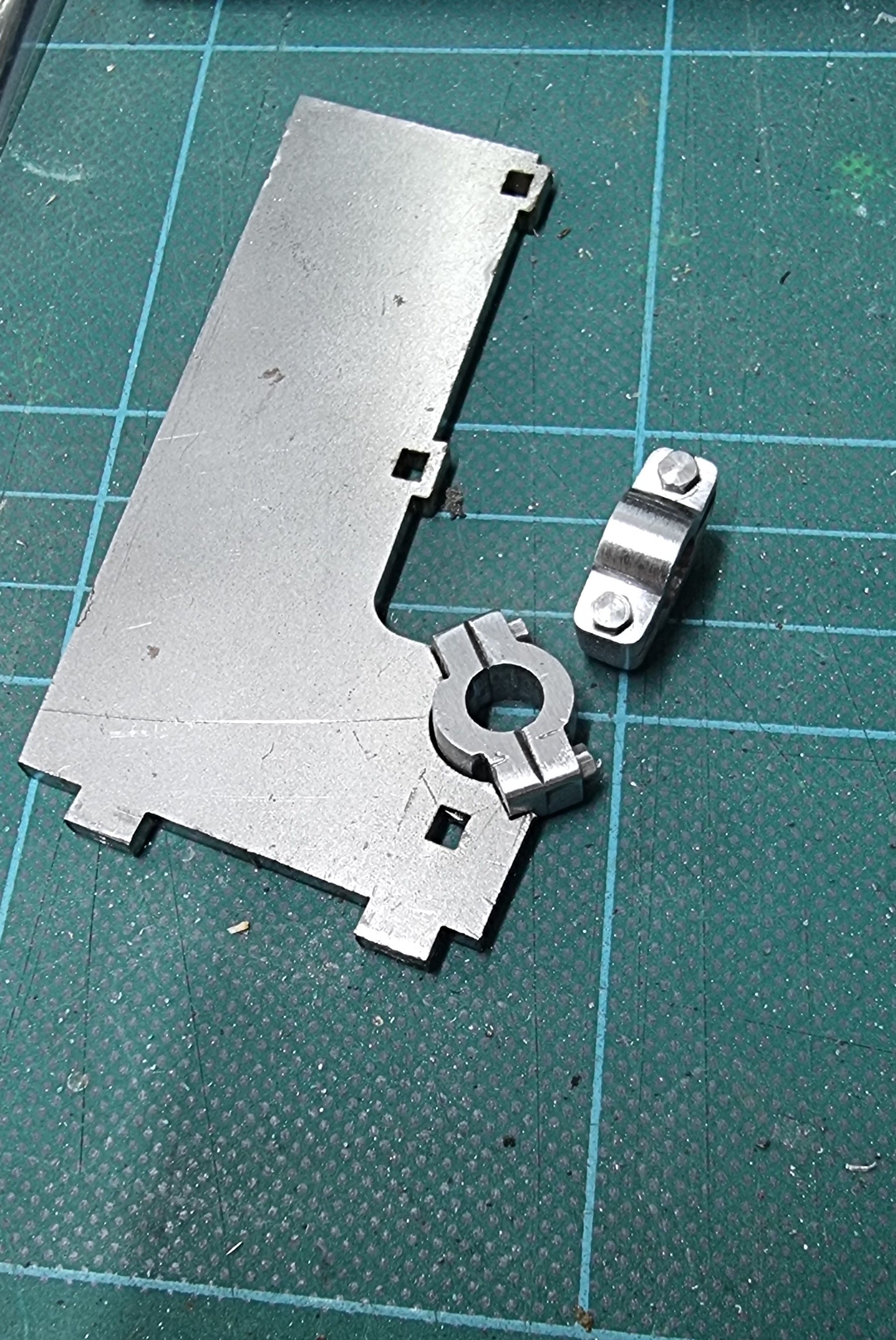
here we see the blocs finished and assembled along side one of the stand sides. I only needed to polish the top of the blocks as the bottoms only needed to fit into the scalloped recesses for silver soldering.
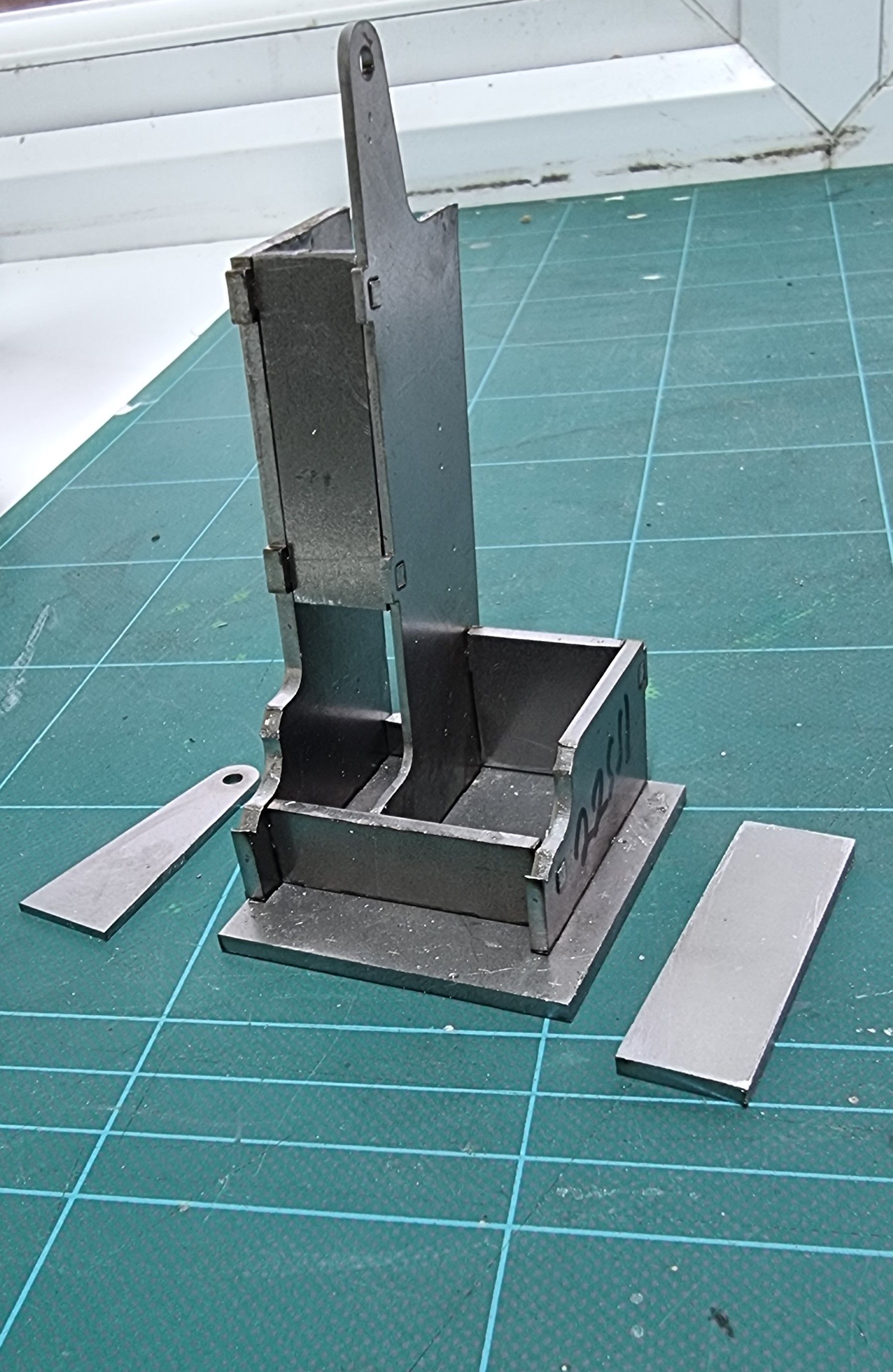
The last picture, for now, shows the parts worked on so far now dry-fitted together. A few things to point out, you'll note that the top bearing mount which is a separate part from the left side upright has been drilled and temporarily bolted to it. Note also that the other thinner side also has matching holes in it, these will be filled later. Also note that the bracket has a dog leg in it, only small at 1/16th but there nonetheless. I decided that the easiest way to do this accurately was to bolt the already formed bracket (scribed and folded in the vice) to the other side with a piece of 1/16th brass offcut sandwiched between, a bolt through the pivot holes for alignment, and then spot and drill through to ensure that all would line u on final assembly. I then did the same to the shorter side upright that the bracket bolts too, basically using the thinner side piece to plot the holes in both the upright and the bracket that bolts to it. Both the pivot and the bearing caps will be reamed through again once everything is brazed up. The other thing done is profiling of the front vertical plate as per the original photo.
Next time we'll hopefully see the stand all brazed up and my plan for fitting the shelf over those mounting holes, assuming it works, of course.