getting closer to that big day...:)

It had been raining for most of the day, during a short break in the weather it seemed to perfect time to prove the sanders work...:)
it's time for the model to be prepared for another static display day at NLSME.. here the model is just about ready.

A walk around to show the chassis as she is so far.
A short video to show the chassis rolling after fitting the outside connecting rods.

A test of oil feed to the gudgeon pins to prove that they work as intended

A quick test to decide on the best suited crosshead oil reservoir feed pipe size for both scale and feed rate, the smaller pipe (0.8mm bore) turned out to be the best choice.

testing of L/H outside cylinder draincock linkage

2:1 Conjugated valve gear test fitted to the model for the first time
Underside tour of the model with its brake rig fitted
initial brake test, once the model is finished and sitting on rails under it's full weight the brakes will be given their final adjustment to suit.

early stage for testing the tender brakes, the movement seen here, although small was enough to lock the wheels solid, Later I gained more by changing the rubber hoses for silicon.

Hi guys, Hope you all had a great 'New Year'....trying out the 'slideshow' option...here's the first for the tender..hope to get back on the build during next week.....cheers...:)

Posted by Building a 5" gauge model of 4472 Flying scotsman on Saturday, 7 January 2017
The tender gets nearer completion

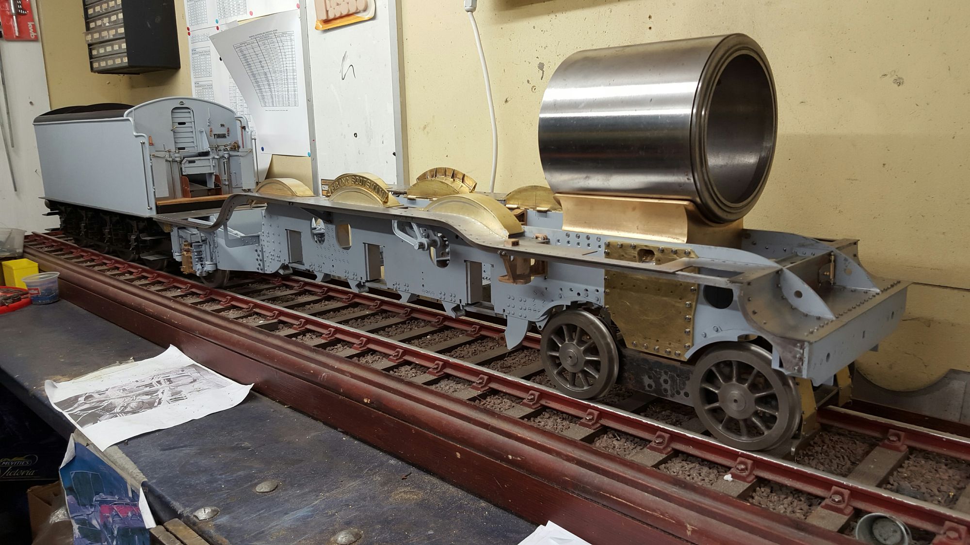
tried another for loco with less photo's. last was too bad a quality....

Posted by Building a 5" gauge model of 4472 Flying scotsman on Saturday, 7 January 2017
the model begins to take shape
One of those 'milestone' moments when the chassis rolled on all of its wheels for the first time.....
These stills show the process I used to machine the door ring and the door itself. The door ring, in particular, was pushing the limit size-wise of my lathe but I got there in the end. I have followed full size with the door ring and machined a groove to take a seal, in the model's case this is a silicon 'O' ring. The 'O' ring seen in the picture was a test, I now have a black 'O' ring so that it blends in with its surroundings. In fact, IIRC I have approx 20 of the things as I bought them in bulk, should last me for my lifetime. The resulting seal is perfect, the ring is held in place with a special cyano glue for rubber, not really required but makes opening and closing the door very easy without needing to fiddle trying to get the seal in its correct position. The door as seen here wasn't finished and had some more profiling done to it later.
This was early days, here the loco is being checked for its ability to negotiate one of the tighter curves oat my local club track, this particular curve just happens to be near the steam bays so not too far to push. I was also checking, that the gap between the loco and tender worked, it did without fouling but I have since discovered, much later in the build, that I need a little bigger gap for the cab and tender doors to have the correct prototypical spacing. The doors on this Gresley pacific needing to interlock, I can't say if this was the same for all of the class, but so far I don't recall seeing any A1 that's different.

No brake valve fitted yet so had to disconnect airline to reverse direction, you'll see this at the end of the video. using the old trick of pipe in hose to create a vacuum.

A quick test to ensure that the vacuum cylinders are working properly, model is sitting upside down for this test.
This short video was the first test of the cartazzi axle spring rate, the springs could support over 100lb in this video, that is, it took that amount of weight to bring the spring down to its correct riding position.. Later, I reduced their strength (replaced more steel for Tufnol leaves as it was too strong for the chassis with little on it. I may need to slightly reduce their strength further as the model progresses, with the boiler attached the model is still a fraction high at the rear, this could be for a number of reasons. The springs are still too strong, the hangers need adjusting, the loco isn't at its full weight yet, the front bogie springs need adjusting or the bogie needs more spacers between the bogie and yoke. I note on the prototype that there are a few such spacers (massive penny washers) fitted today. This will all be sorted once I have built a set of weighing scales to weigh each axle independently which sitting on rails.
This is an early test off 4472's steam sanders, just using compressed air for now. Since the model is sitting on its rims most of the sand ended up on the workshop floor but you can see that the venturi is working as per prototype.
This is a test on the cross rod that connects the two gravity sanders together, just checking for the amount of movement and clearance. You don't actually need that much movement as the small hole in the valve that the sand falls through is only a NO.50 drill. There will be a number of video's showing the apparatus.
A pre-test just to check all is well before final fitting to the loco, for those interested, the sand used is childrens play pit sand. Everything is to scale, that is 1: 11.3 (5" gauge)
With the gravity sanders fitted and the linkage all connected including the lever in the cab, it was time to check it's operation. I am rocking the lever as I have seen done in full size, I discovered later that if the lever is left in the 'open' position, ie, no rocking motion, the sand falls out freely, best remember to always have it closed. As long as the sand remains dry they will continue to work and work very well, all to scale too, this is exactly the same scenario as on full size. I'll probably empty the boxes after each session to ensure no damp builds up while sitting in the workshop...:)
The cylinders on this model are not what you might call 'a normal affair', these are blind bored which makes things a little more involved, this has been described in detail on my FB build page and will be on my new blog in due course. Those eagle-eyed among you may notice in this video that the lathe is in reverse, this is using an old industry trick to burnish and thus polish the bores on the reverse cut. I put the lath in reverse for all of the return cuts and finished the final cut this way. The boring bar itself is only 1/2" as that is the size of the piston gland opening, this then has a collar fitted to it on which I have set two tool positions. One is angled for boring, the other has a knife edge vertical face for machining the face. BTW, for this particular cylinder, the face in the photo has to be cut by hand as the steam chest to too close for the chuck to swing, you can begin doing it under power until you get near the steam chest, then it's over to labourious hand cuts. The final reverse cut results in a highly polished surface, the tool was designed so that it had a rounded blunt ish curved back edge which is the part that did the polishing.