Continuing from part 3 I am finally getting something assembled that looks like a Gresley reverser. I'll give a few details on the extra detail items covered in this article first. As stated in the beginning I decided to have the shelf hinged to make it easier to reach the cab floor mounting bolts, this presents a few obvious changes to the prototype, I already mentioned the omittance of the 12 hex bolts to allow for the shelf to be able to hinge up for access, on top of that the shelf sits a little lower as I'm using the pre-cut tabs as the hinge pins which leads to one other change is the small angled vertical plate which now needs to be deeper. Yes, I could spend yet more time making these parts as per prototype but they will be difficult to see anyway once in the cab and I do still have an awful amount of work to do to get this model completed, thus I took the easier route.
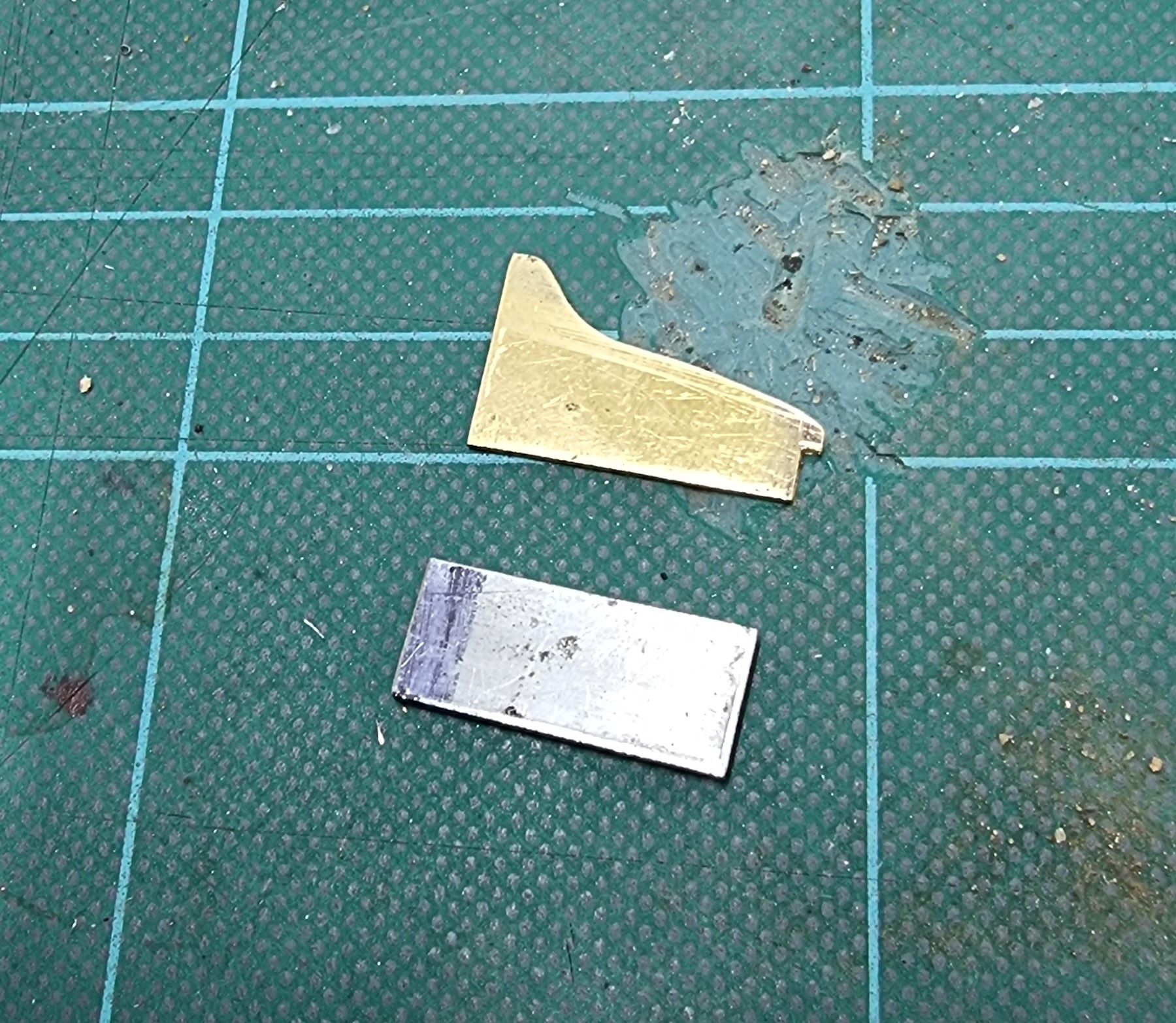
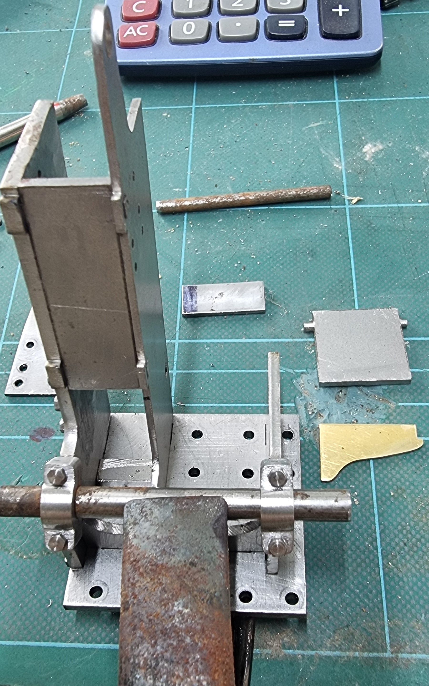
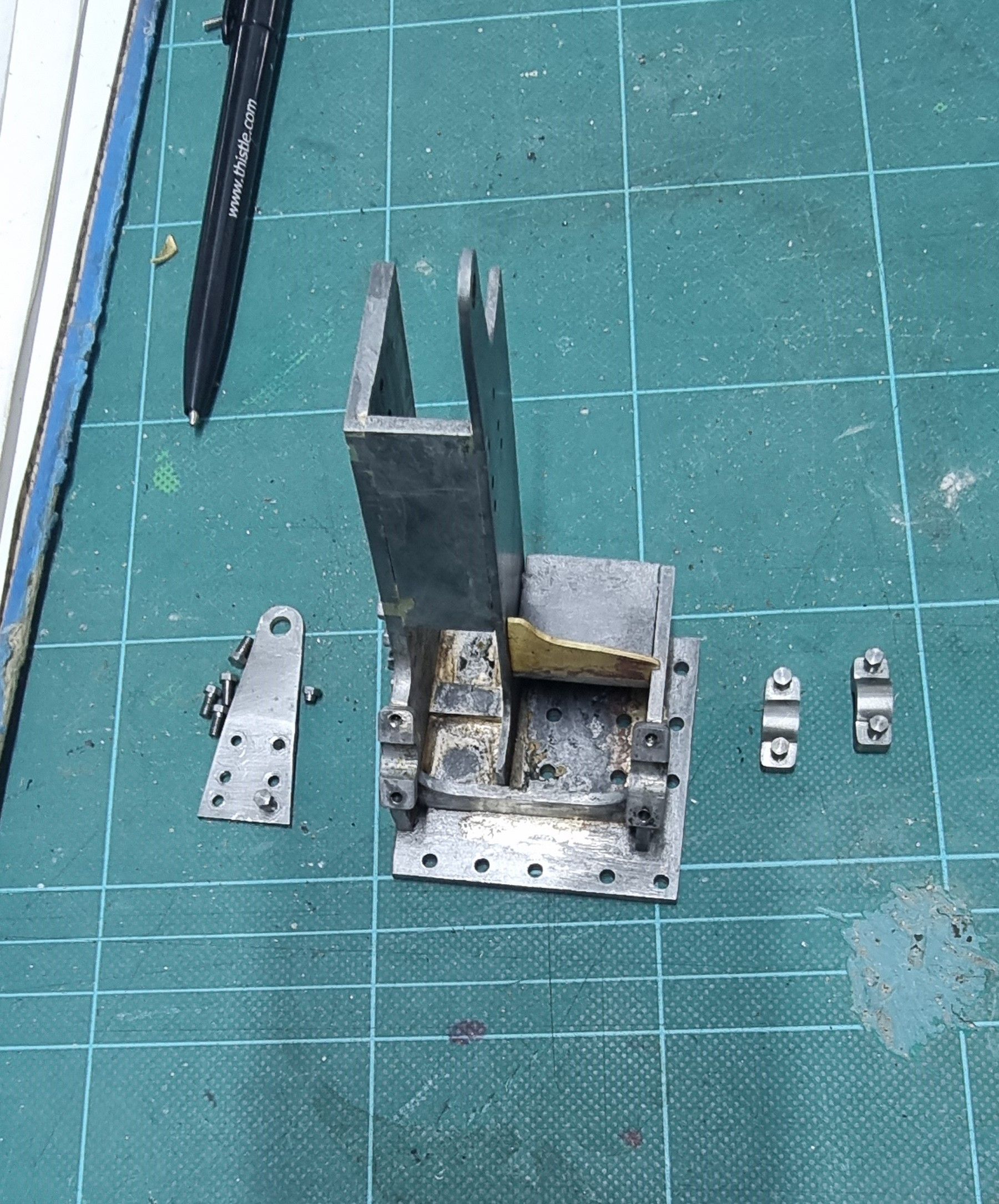
The two cut parts in the photo are to do with having the shelf hinged, the steel plate below adds back the strength to the side plate which will be lost with a moving shelf and the brass shape is a representation of the small angled plate that sits along the front edge of the shelf, it's , of course' deeper here due to the lower shelf position required to accomplish the hinges using the slots already cut.
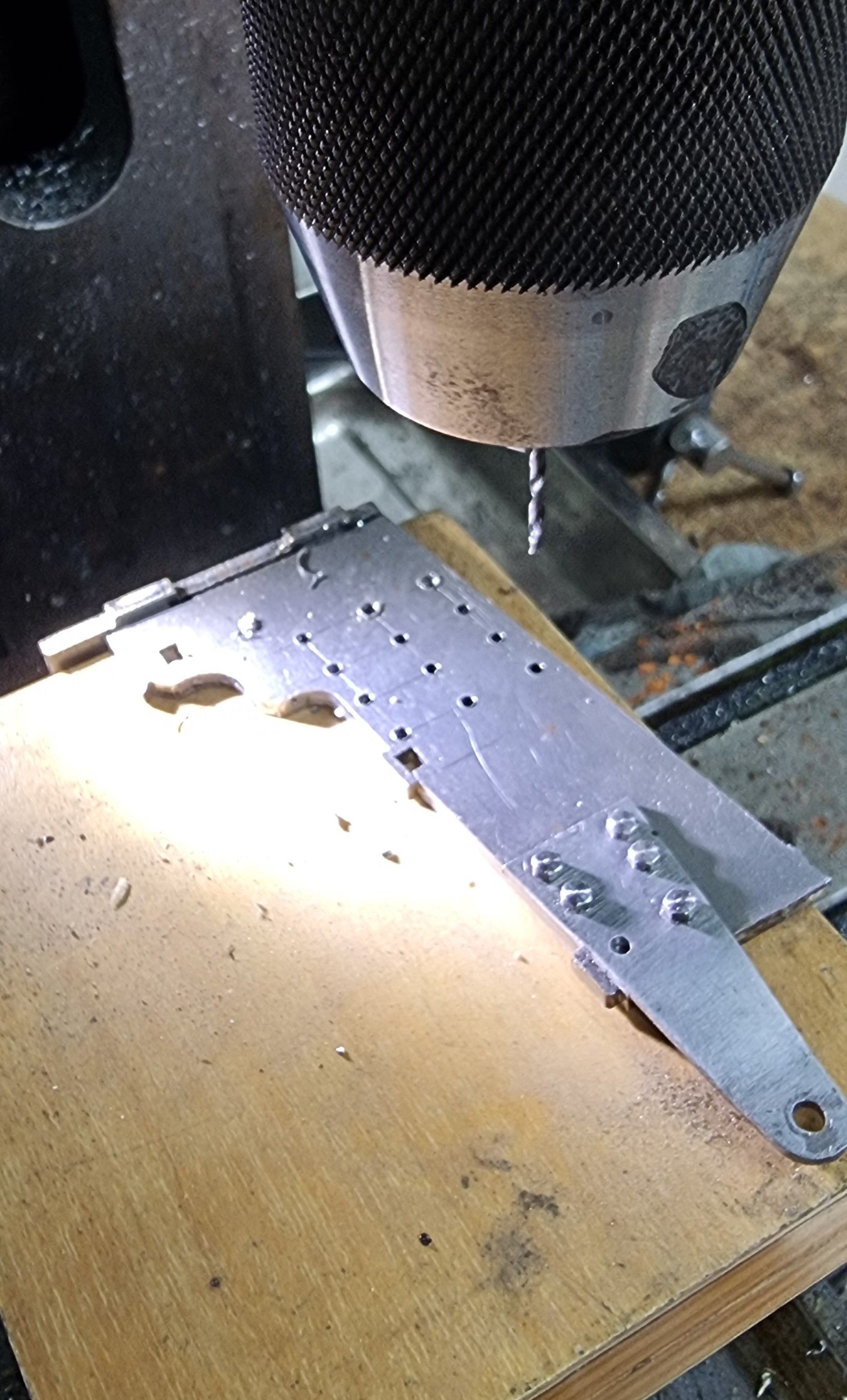
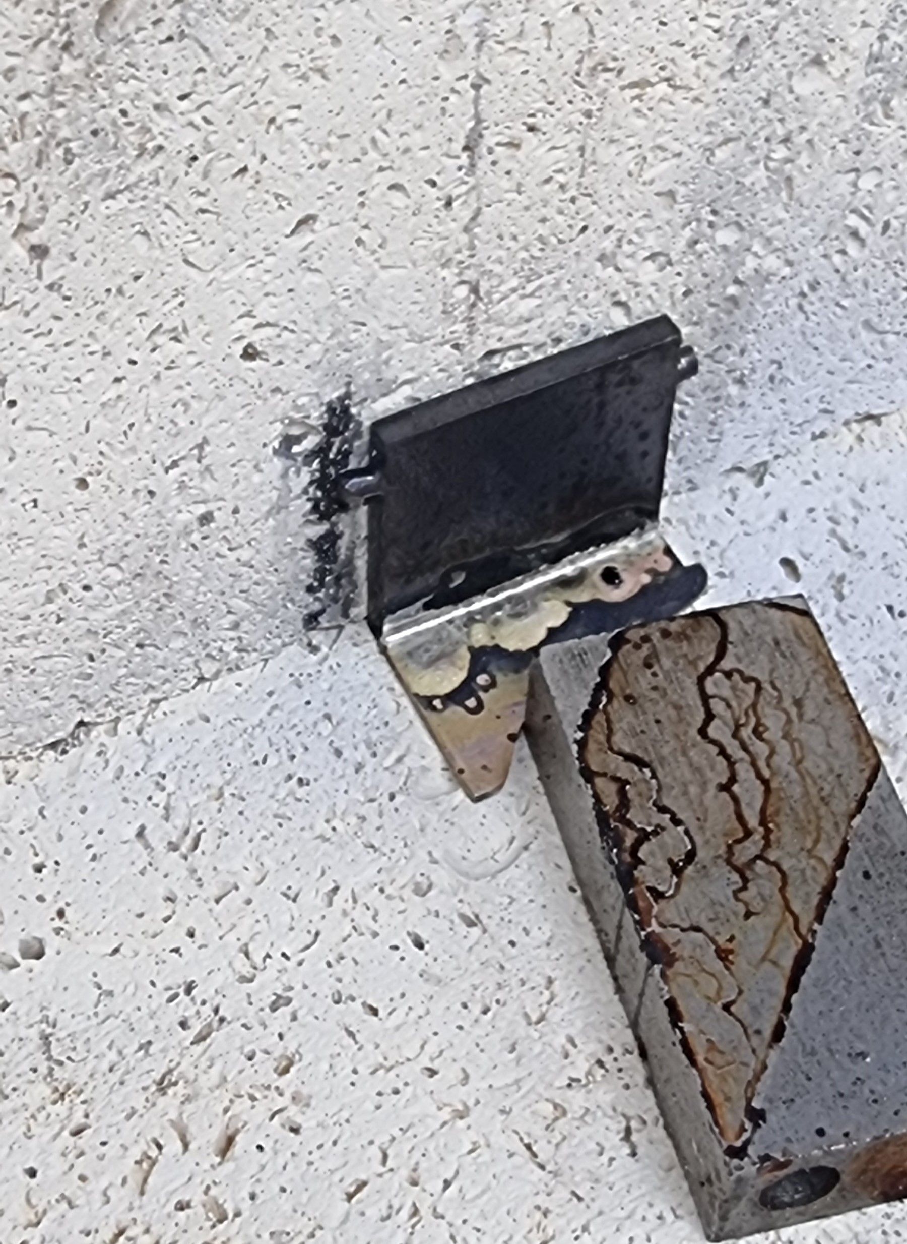
The next extra was the 12 8BA hex bolts in 4 rows on the inside face of the assembly, outside omitted as discussed. As can be seen, I have taken advantage of using the base to hold the part square for this operation.
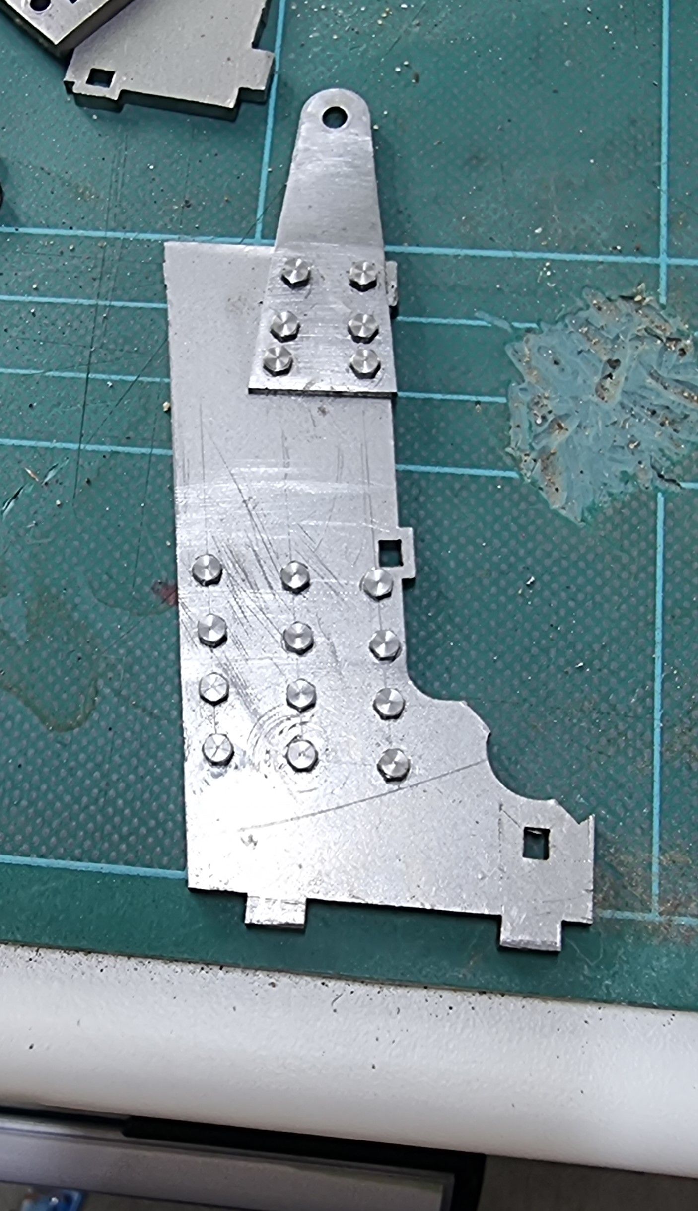
Here's the side with its bolts mounted and cut flush with the back face, note the bearing plate isn't fully aligned in this photo, which will be tightened fully once the assembly is brazed together ensuring everything sits squarely.
We are now ready to braze everything together which I plan to do in one go except the various bearing points, I'll get the bulk of the job done first so I can fine-tune the bearing positioning in a more relaxed atmosphere. The next picture is the last dry test fitting of the various components to make the reverser. There will be lots of final cleaning/fettling before this is finished.
Before brazing the main body I first tackled the shelf and its modified angled upright, these were pushed against the hearth bricks and held in place with a little help from some scrap steel. All parts were checked for squareness before heating.
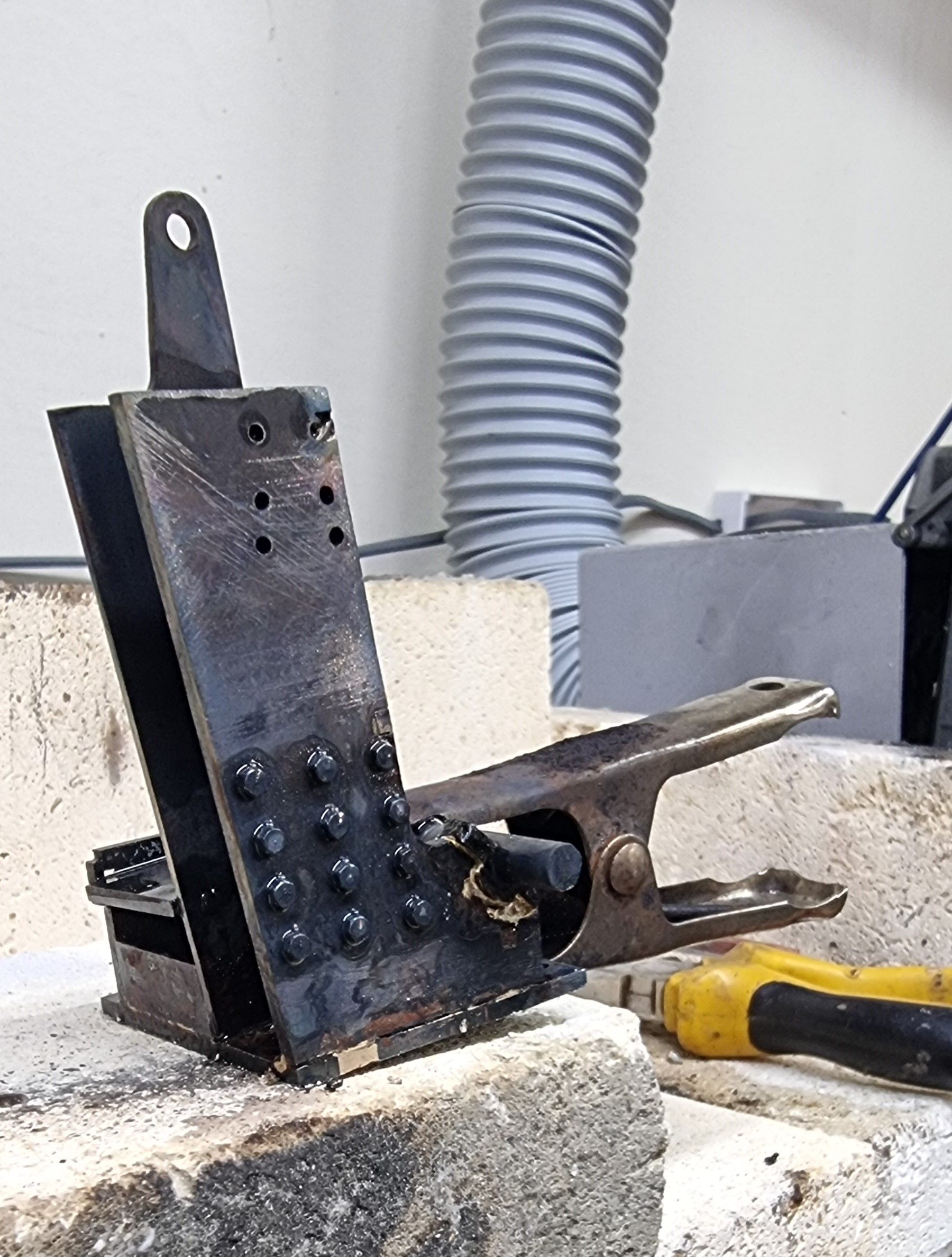
On to the main body, alas in my eagerness to get this done, I forgot to take a picture of the first stage, the second being attaching the lower bearing blocks so I will describe both stages with just the one picture. The reverser body parts were individually coated in flux and then one by one put together. Next, I cut up suitable lengths of silver solder and placed these on the inside of the body, the plan being to protect them from direct heat as it's applied around the outside. I then applied yet more flux over the silver solder strips to ensure there was plenty as the heating session would be longer than normal, it took approx 10 minutes to get the solder to flow. I used a metal clip to hold the upper section together and square. After cleaning I attached the lower bearing blocks as seen in this picture although when heating it was the other way up to let gravity help. Before heating, I checked that the bearings were square by measuring the distance of the metal rod holding the bearings in place, checking both height and distance from the front edge.
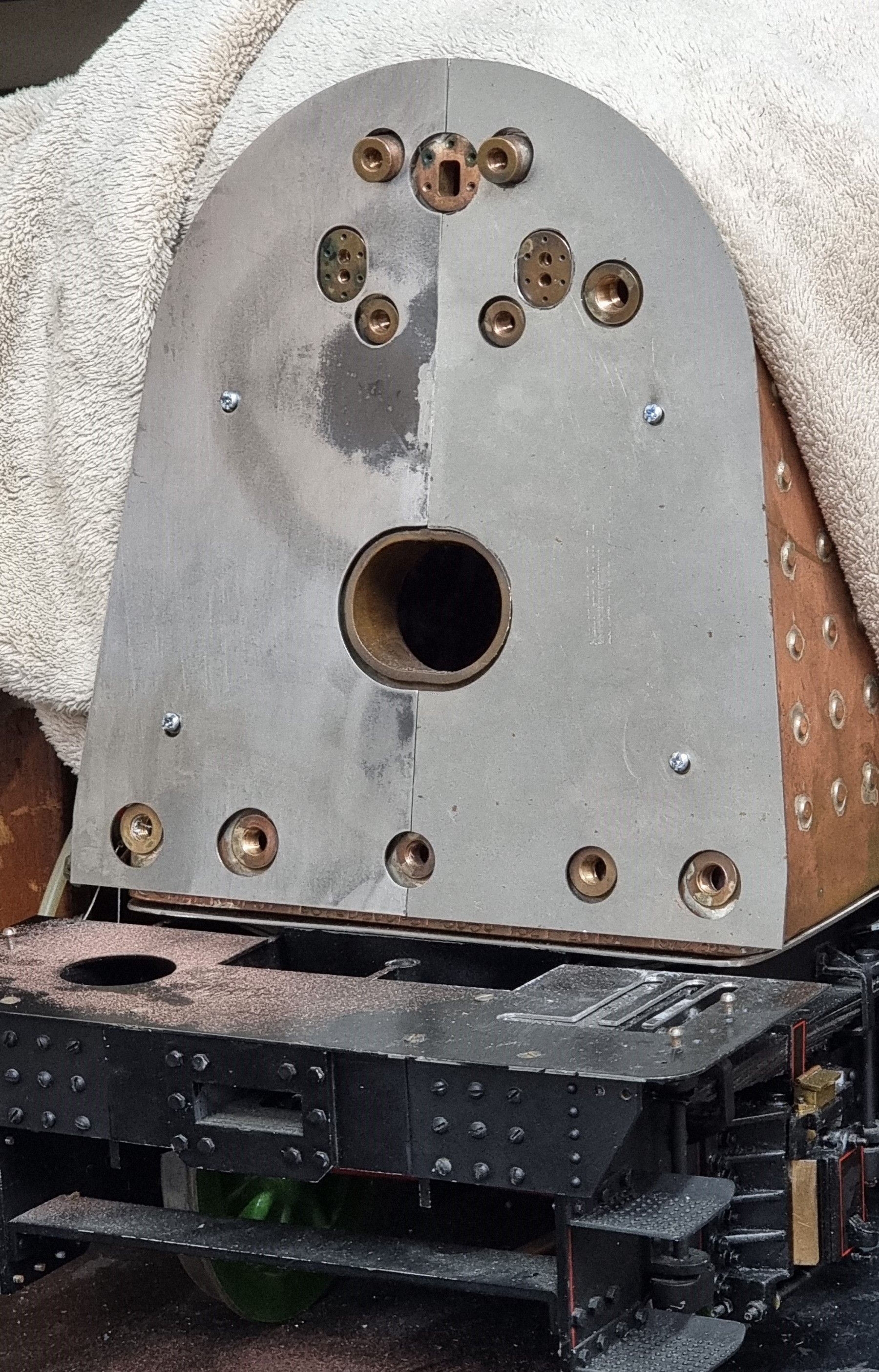
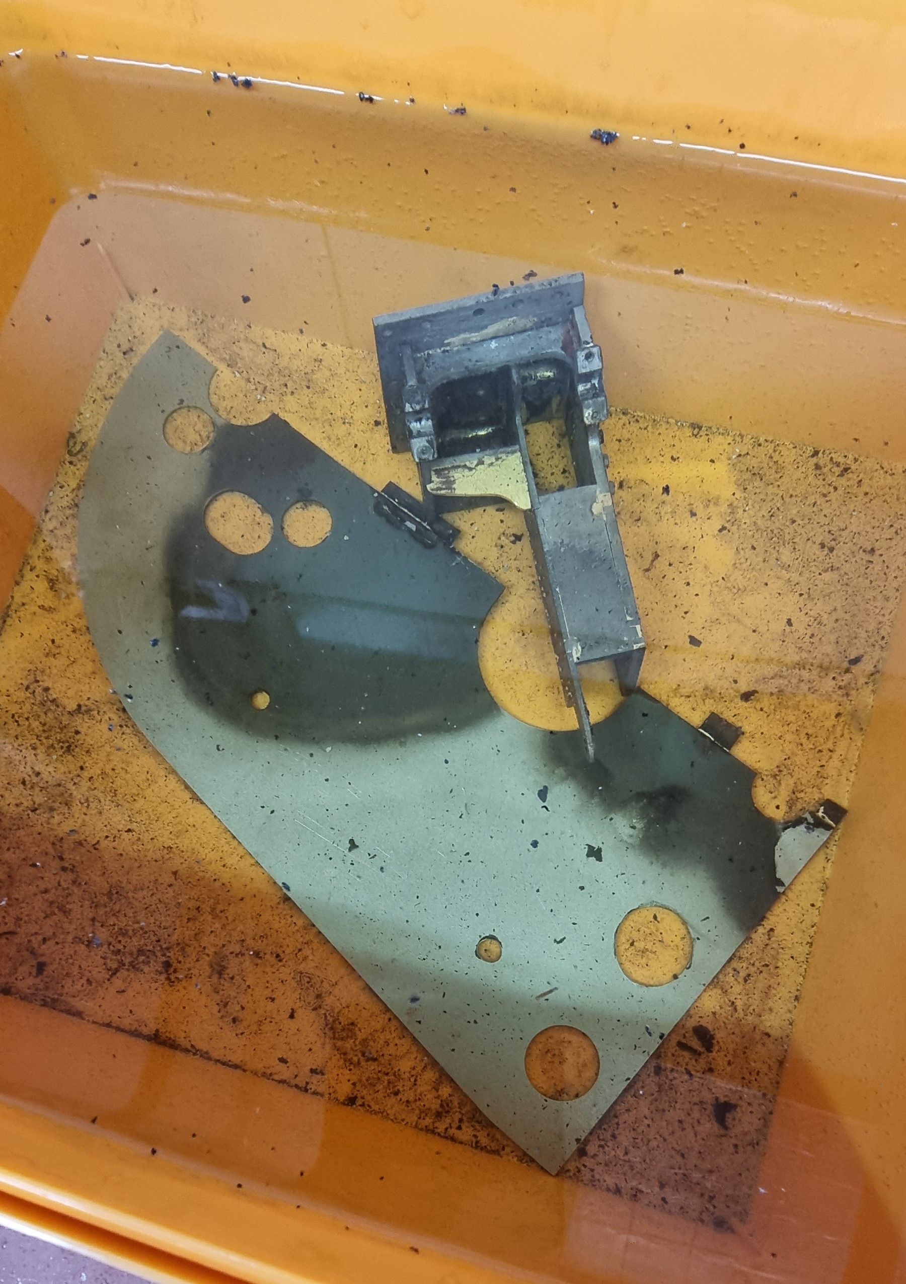
this was then soaked in citric acid for cleaning, in this picture you can also see one half of the backhead cleading to which I attached some steel strips to keep the two halves when joined in line.
This got us to the stage of the basic body completed except for the final filing/cleaning and painting, I also have some more holes to drill/tap for auxiliaries to be mounted. I also still have the bearings to make and then align/attach to the top mounts which I'll cover soon.
Next time I'll make a start on the working internals, plus some work on the backhead cleading. I need to do the two in tandem as the reverser indicator slide needs to be positioned correctly to the leading, I'm still researching its operation but I think I have a fair idea of what's what. I'm always happy to hear from any of you guys who are familiar with the full-size workings. I finish with a taster picture of the cleading, with lots to do here including shaping the top and sides to curve around the firebox, I may even try my hand at an English wheel for this, that will be a first for me.