NB: I had thought that I would be giving more detail on the buffer beam at this point as it was the next item to show in my log but on looking at it this morning it only covered the fitting of the buffer housings, I'll do that perhaps in the next entry which will see a start being made on the smokebox and saddle.
Brake Shaft Trunnions...these are one of those tricky castings that are prevalent in a Gresley Pacific, the spring brackets being another favourite...lol Tricky in as how to hold the things for the various machining operations, I'm sure that others may use a different approach. Such things are dictated by the tools/equipment that one has to hand, this was my method which worked well.
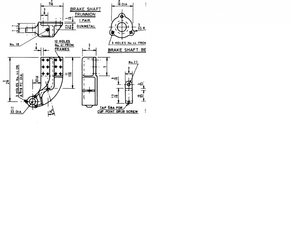
First off a picture of the drawing, saves me writing down all of the measurements in this entry.
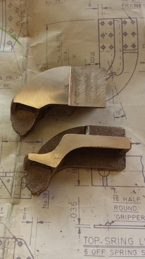
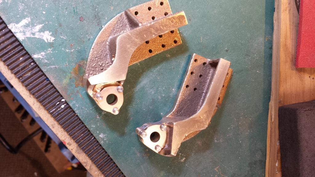
Here we have the two castings having been split apart, as with the horns etc the two trunnions are cast as one. Before parting they were first machined to overall thickness and then had the 1/16 rebate machined in the centre before sawing in half to give the two castings as seen in the picture. Next job was to clamp each one of the castings in it's correct position to the frames and then transfer the hole positions across.
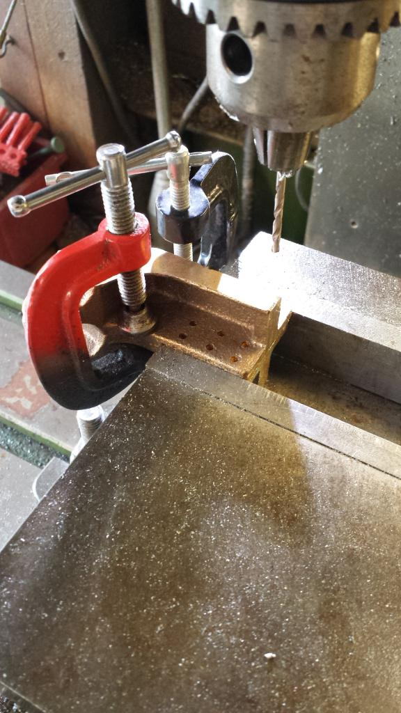
The holes were then drilled on the first marked casting, this was then bolted back to back with the other, held in the machine vice and the holes drilled through to the other casting, giving two castings that when riveted to the frames will be in the exact opposite positions. Clamps were used to hold the two casting's together with a 1/8 piece of steel flat bar used to space the centre machined section and thus keep everything square.
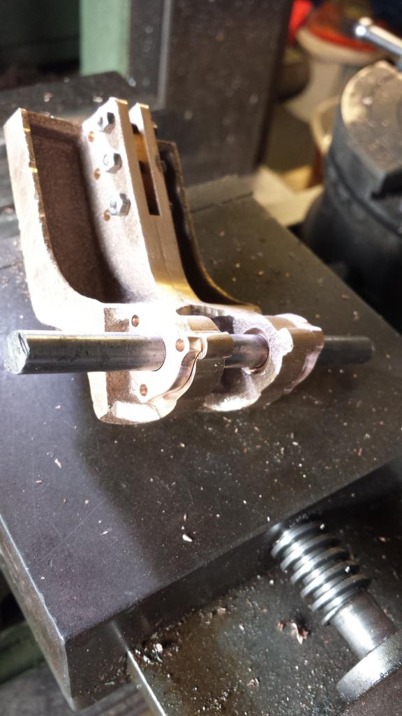
With the mounting holes drilled, the two castings could then be bolted together using suitable bolts for machining of the remaining sections, sides and tops. It was at this point that I noticed that the two castings weren't symmetrical, as seen by the mounting spigots around the bearing journal, a pain but something that I could work around.
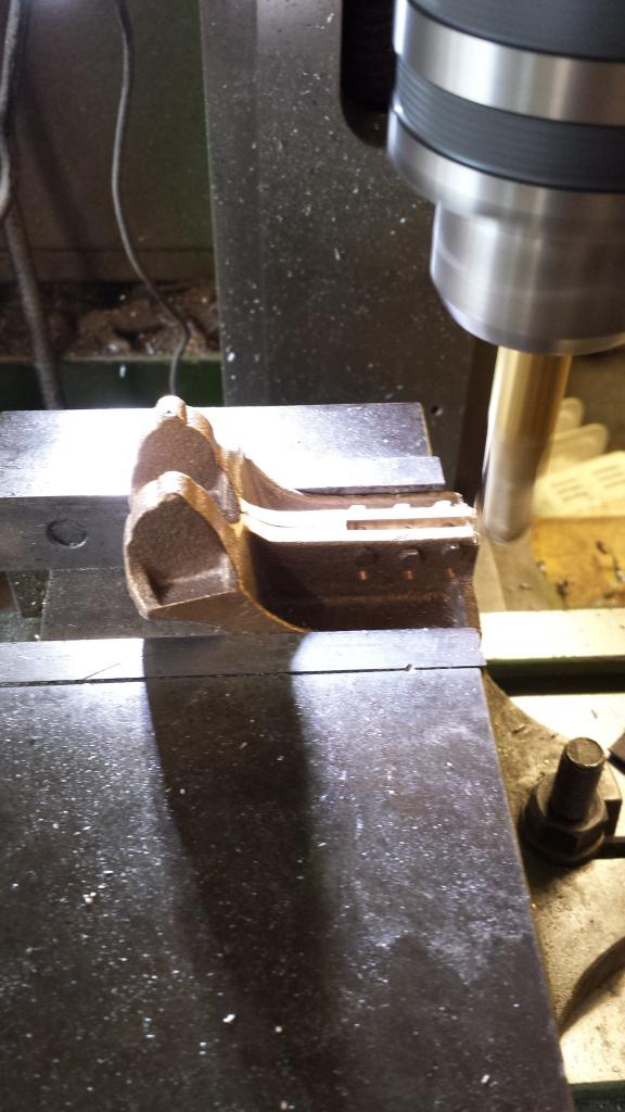
back in the machine vice the bearing journal faces were machined flat
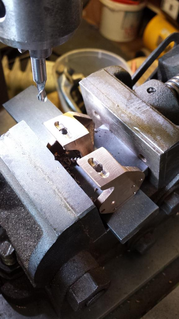
Next was to machine the holes ready to accept the brake shaft bearings, If you look back at the drawing the centre of the holes lie's 15/32 from the edge of the trunnion, I kept this size but adjusted the centre height a little to try and get the hole close to centre for both trunnion's, bearing in mind that they were not symmetrical. The way I saw it, it's far more important to have both holes correctly aligned for the brake shaft than to have each hole in the centre of it's trunnion journal, after all once the bearings are fitted you can't see the trunnion behind.
This picture to shows the trunnion so far, note that I have worked the outside profile a little using files and a belt sander bringing it closer to the drawing, I could have done more here to centralise the bearing hole but decided to do the two bearings first and use them as a final guide to the outside profile.
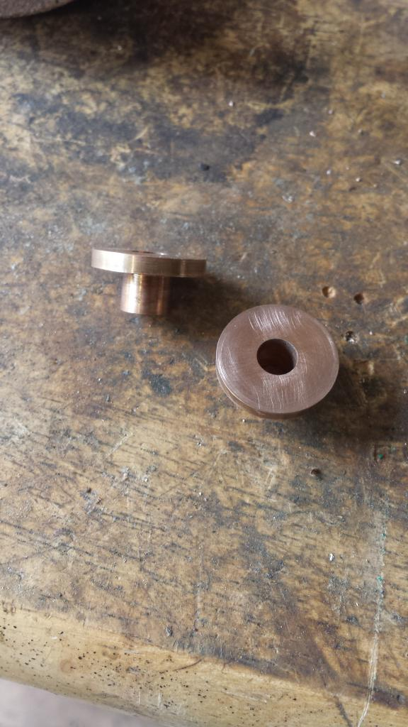
Ok, so the next job was to machine the two brake shaft bearings, all plain turning, 3/4 bronze bar, bored to 1/4 and then reduced to 11/32 for 1/4 length, final turning job was to part off leaving a 1/16 lip, so in essence a top hat.
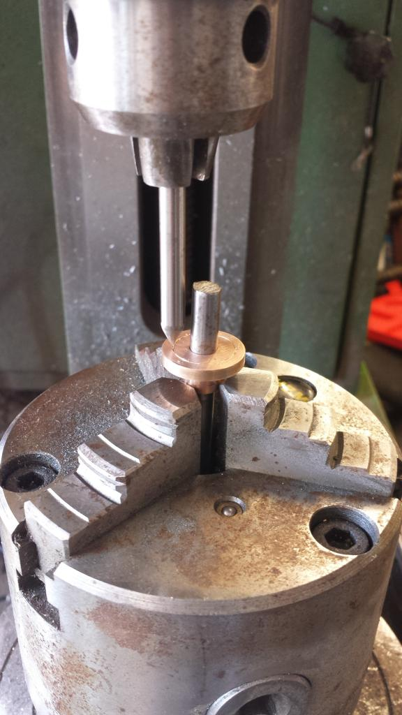
Over to the rotary table next, the bearing is held in the jaws with a length of 1/4 steel to stop any damage from crushing, I ascribed a 9/16 circle which is the PCD for 3 no/44 holes and also the outside edge of the bearing between the spigots..not a very good description, all will become clear soon..
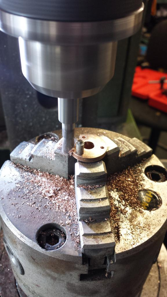
Next job was to drill the 3 bearing securing holes at naturally 120 degree spacing and then to machine away the unwanted material between the spigots, I cheated here, didn't see a reason for setting up an index but also didn't want to rely on the dial markings alone so went for using a spacer positioned in each hole and just machined up to the spacer, not the engineers way but good enough for the eye in a non critical situation.
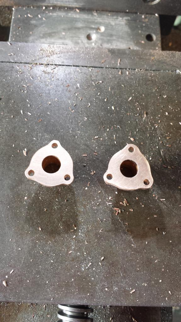
I then rounded off the spigots by hand, not completed finished yet in this picture, just needed a little more tweaking but I decided to leave the final shaping until the bearings were bolted in their positions on the trunnion, easier to hold but also I can see how they are compared to the bearing bolting face.
Here I am checking on how things are fitting together, as can be seen I still had a lot more work to do on the trunnion bearing housings before they matched the bearing profile. Bearings are a nice snug fit in their housings and I have deviated from Don's words in as far as I will transfer the holes from the bearings to the trunnion housing rather than the other way around, makes life easier using the rotary table. BTW, the marks seen around the outside from the various clamping positions during machining were filed smooth at the end.
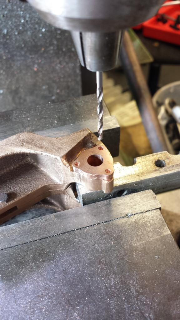
It was then time to transfer the mounting holes onto the bearing housings. Here with the assembly back in the machine vice I clocked the bearing to it's correct position ( allowing for the fact that the spigots on the two castings aren't symmetrical) , lined up with the 3 holes and in turn drilled through into each trunnion using a no. 44 drill ready for 8 BA bolts. The part was simply inverted to do the same to the other side.
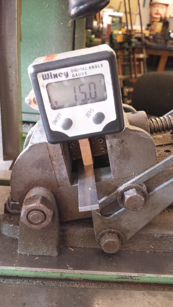
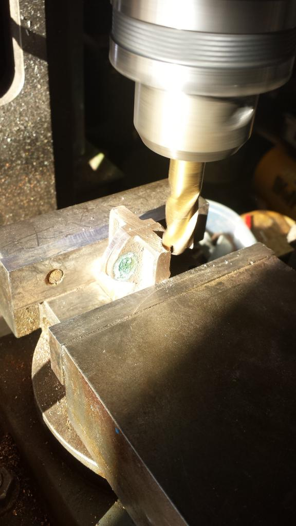
On to the last machining job for the trunnion, that being the no. 18 holes for the spring hanger bolts to pass through, these were drilled at 15 degrees to the vertical. this was a job for the tilting vice and what's becoming a favorite little tool of mine, the digital angle scales...BTW, the scales are calibrated on the mill bed for each use.
Picture just to show the scales set at the required angle, of course the vice was also checked to ensure it was square first.
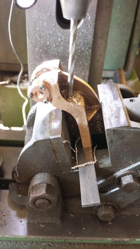
finally, first centre drilling and then drilling the two no. 18 holes to complete the machining process.
This just left the final profiling of the brake trunnion around the bearing housing to finish, I mixed up a little JB weld and applied it to the area concerned. Once cured I made good the shape using the belt sander, files and a 3M sanding pad to finish. Once painted it would be invisible, not that you could see it back then anyway.
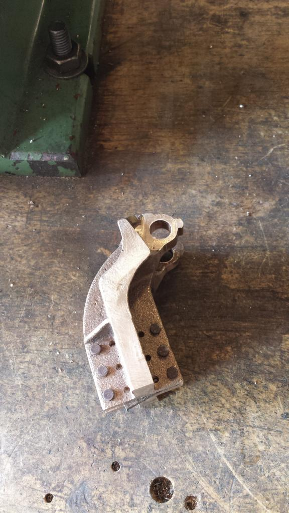
and so, here we have the completed trunnions ready to be riveted to the frames
It was then time for the spring hangers.. hmmm
I have to say that these were not my favorite item to machine...bloody nightmare although I managed to get through it without any mishaps but boy were things stacked up against me...lol
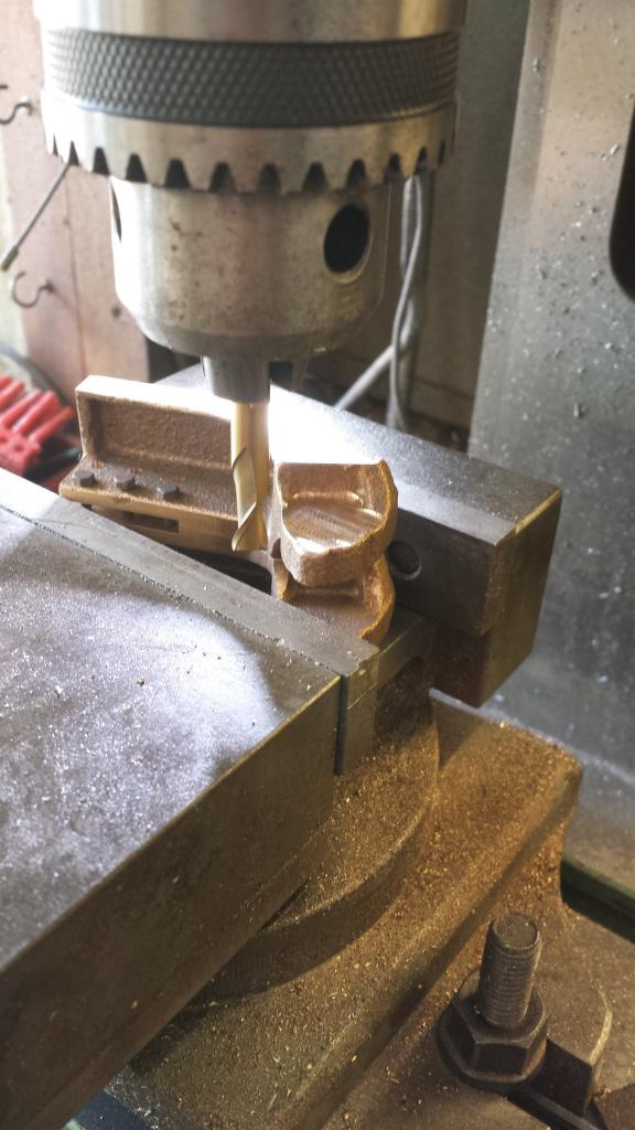
I thought that I had a picture on file showing the castings as supplied but alas can not locate it so first picture is after the casting had been machined flat, top and bottom, to thickness and then cut into two halves. The castings were terrible, a mixture of bad pattern mixed in with poor foundry work. Bad pattern as the two half,s did not match, different shapes and webs in different positions and foundry as the castings all varied I suspect due to shrinkage assuming they all came from the same mould?
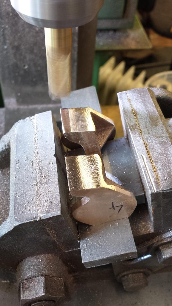
Now due to these issues I needed to find a datum somewhere, normally when dealing with two halves joined together I would machine the ends square to give me a starting point but this wasn't possible due not only to the shapes not matching but also due to them being of different sizes due to the shrinkage. I chose to use the upright ridge section of the casting as the datum even though these weren't great. Having split into two the halves they were then held back to back in the machine vice, using a square sitting on the vice top edge to square up the casting ready for machining. The two halves were lined up buy their lower front toe and the central ridge in the casting, ignoring the shapes of the faces that mate against the frames. You can see in the picture how these two faces do not line up and this wasn't the worse of them, the important thing was to ensure that they were not only central but that they would cover the holes machined in the frames ready to accept their fitment.
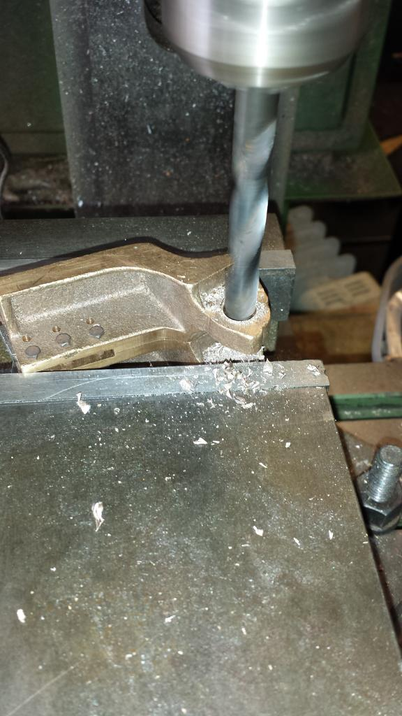
Next I tackled the 15 degree toe angle, I used two pieces of steel bar to hold the castings via the central ridge , a couple needed shims due to the ridges being slightly deformed but the object of the exercise was to get the castings sitting in their correct positions to ensure that they all matched to a set Z axis reading which is 1 1/4 inches from bottom as seen in the picture to the centre of the hole position for the spring hangers.
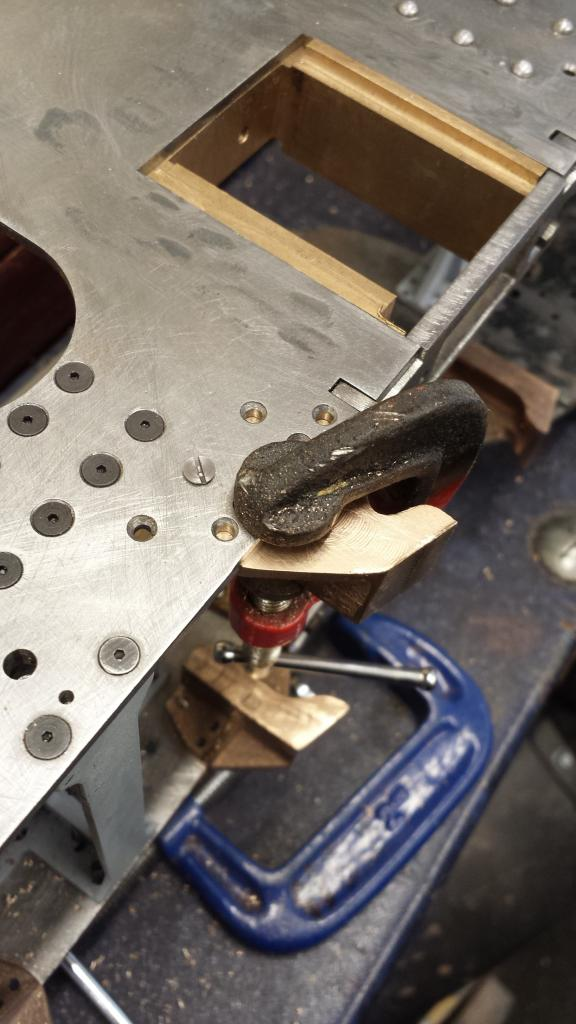
having succeeded in getting that far things were beginning to get easier, I ascribed a line 1/8 down from the top of the casting ready for marking out the first two no.41 holes, each casting was in turn lined up with their associated holes, the rear most hole was marked and drilled in the machine vice. This gave me a starting point to hold the spring hanger at it's correct height, I then lined up the other top hole and clamped it to the frames as seen in the picture. I then drilled the next hole and held that with a bolt too, this continued until all holes were drilled. When one side was done I did the other checking closely that they matched the other side, I had originally planned to do these the same as the brake trunnions, IE do one, bolt back to back and transfer the holes across but decided that I'd rather do it separately due to the two halves not being perfect matches and thus to keep an eye on what was going on.
Once the ten spring hangers had been drilled they were again placed back in the tilting vice in pairs to have their no.18 holes drilled and have the recessed groove cut for the shock absorber's to locate, BTW I forgot this groove on the brake trunnions earlier so did those at the same time.
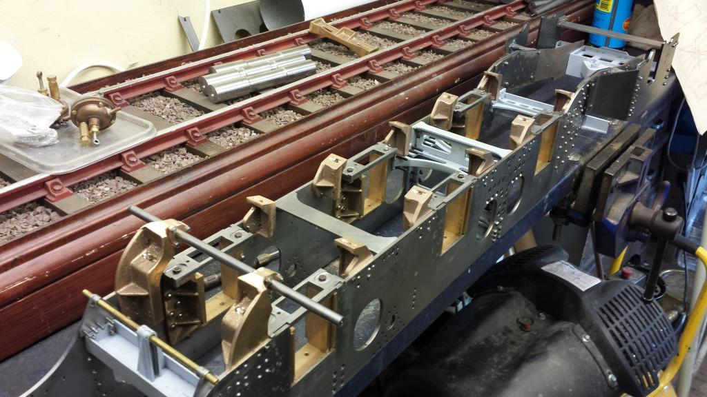
And here we have the chassis with brake trunnions and spring hangers in place, note the brake shaft steel bar is only a temporary item for alignment which i'm happy to report is good, as is the brake cylinder alignment. There's still a lot of riveting to be done here but it was getting there slowly.