
MB: This part is where I really did appreciate the wonders of modern technology with laser cutting. It didn't take too long to fabricate the following parts, If I had to have cut them all out by hand I wouldn't be as far into the build as I currently am. I also doubt that I'd have the stamina to include all the high detailed parts which even at the stage I'm at today have barely begun.
So I began looking at the various parts that Malcolm cut for me that still needed assembling and that required the frames separated to spot the mounting holes. First up was the trailing frame spacers, these are lovely little things that space the trailing frames away from the main frames forward of the cartazzi trailing axle. As seen here these are now ready for silver soldering, as are the next items.
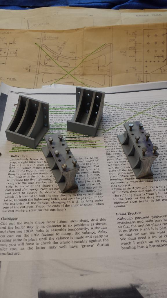
For the next items we have the stiffener brackets, these sit at the rear of the frames supporting the end of the trailing frames, like the previous parts it's important to remember to build opposite pairs.
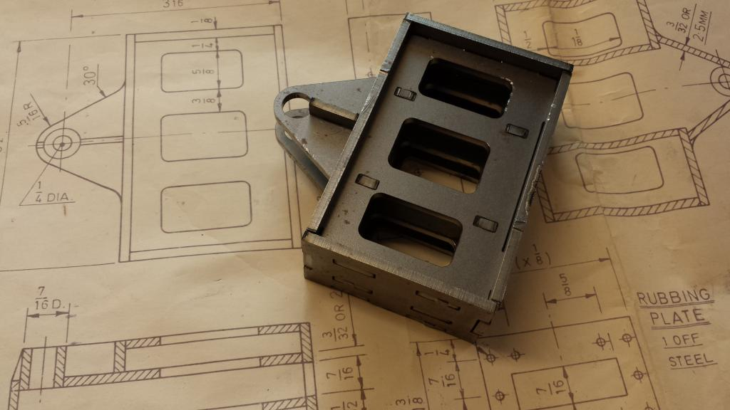
This last part being prepared for a big heating session the following day is the all important dragbox, this is a piece of art and shows that Don's design will be capable of hauling very heavy loads, this of course will sit at the far end of the frames inboard while the stiffeners sit either side of it outboard of the main frames... hope that makes sense..
As can be seen it has three layers and will be very strong. Bits still to add are the pivot bush which I'll turn up before SS everything together and the curved front that needs cutting , heating and shaping to fit around the pivot bush plates as can just be seen in the drawing. All of the above will then be machined square and to final size.
well things then moved on quickly... here I have SS the stiffeners and spacers.. The drag box was done the following day once most of the frames have been erected,.
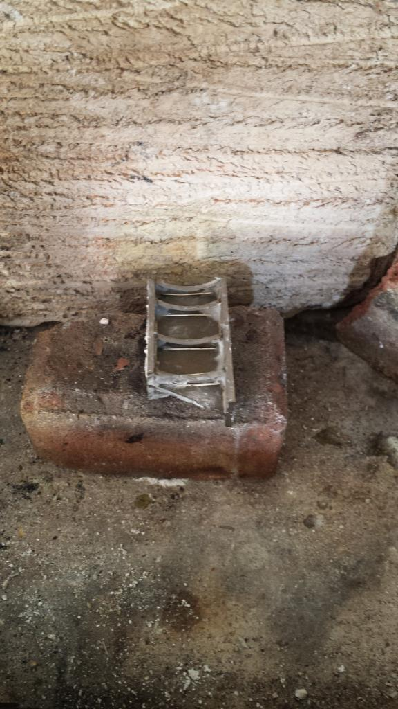
I include this picture just to show one of the spacers all fluxed up sitting in the hearth awaiting it's turn to be torched..
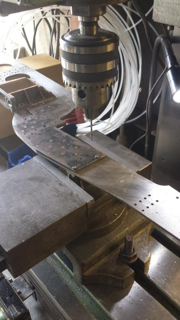
Once I had finished SS the parts together they were machined square and given a coat of Acid 8 and. The stiffeners were clamped to the rear of the frames allowing 1/8 for the drag beam and their holes were spotted through. The spacers had to be done another way as they sit at an angle and thus I couldn't use a square to ensure correct orientation. I plotted two holes according to the drawings, taped 7 BA and then held the spacer to the frame via these two points, I then used a suitable drill reversed in the chuck to spot each hole in turn and then drill for 7 BA . Picture shows the frame held via the spacer in the machine vice with the rest of the frame supported to keep it both level and square.
The completed spacers/stiffeners were then put aside until required..
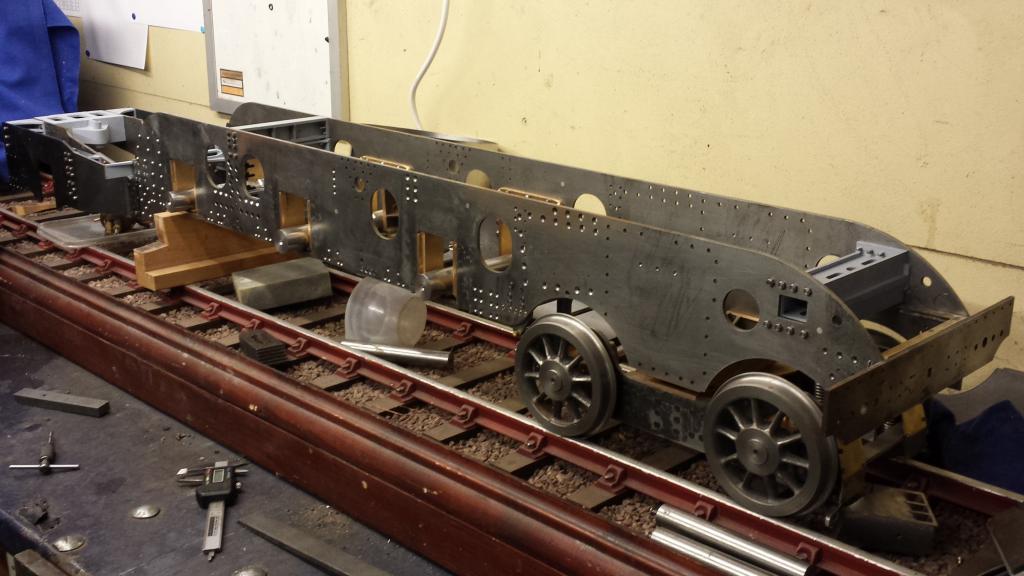
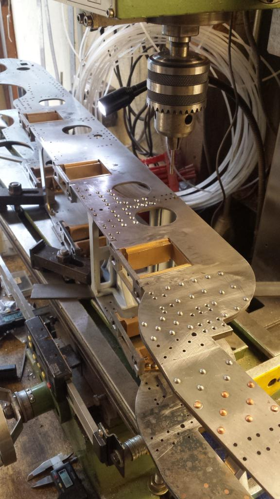
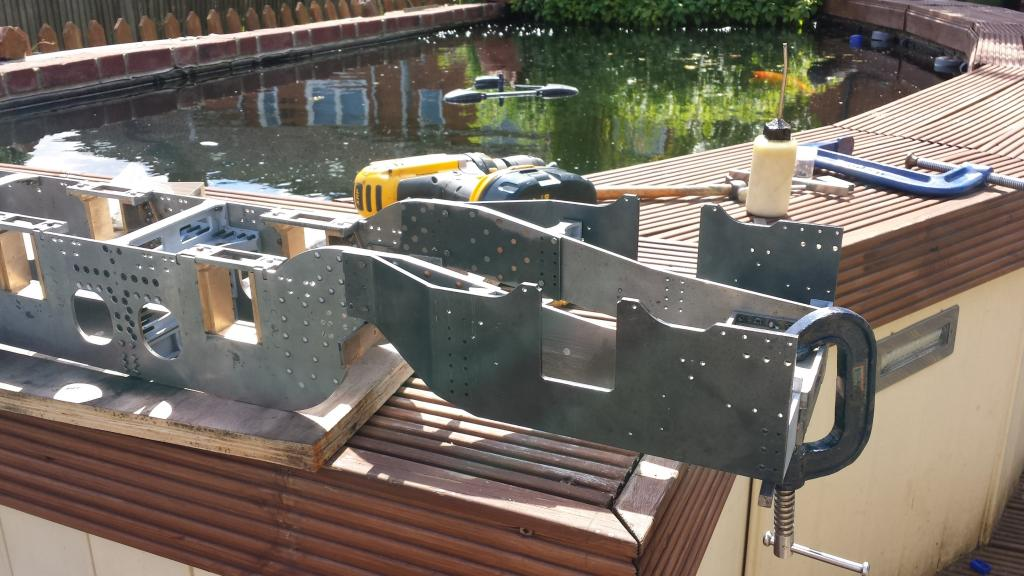
Now I could finally get back to erecting the frames... this took a while but here's a picture to show how I intended to proceed. I reassembled the various stretchers made previously, held with the two bolts for each that I had drilled. I then worked my way through each stretcher, checking that it was square and correctly placed and then spotted through each hole in turn plus tapping all that required it. The frames were laid on their back first to check that they were sitting flat before tightening the bolts, this was then re-checked at each stage as I proceeded.
It was sunny outside the next day and so I moved out into the fresh air/sun, Here we see both spacer's and stiffeners in place, the completed dragbox also in position, btw this is how the frames are pulled parallel again for the model.
Don giving a distance that the end of the frames should be pulled in by, it took a bit of work using clamps to pull the frames to shape while transferring some of the holes to hold the dragbox in it's correct position, then moving the clamp as each row of holes were transferred, drilled, tapped and a temporary screw used to hold together. I had a doh moment here which luckily I double checked before progressing too far, when I set up the dragbox, checking it was square to the ends of the frames and parallel with the top of the frames I forgot that the dragbox needed to be set back 1/8" from the back edge of the frames so that it sits flush with the dragbeam. After kicking myself for not paying more attention I re-positioned and re-drilled, luckily there was plenty of room and no need to fill the previously wrongly drilled hole... note to self ' pay more attention'... I'm sure I've made that note before...lol
So the picture shows the trailing frames held in place with two bolts each to check all is going to plan, I bolted a piece of steel under the dragbox ( or on top if the right way up) to keep the trailing frames level with the cab floor so that I could check they were of the correct length. I'm very happy to report that they are spot on, this was something that I had no way to be sure off until this moment as you can't really tell until the frames have been pulled fully into their correct position. The end of the trailing frames end exactly at the end of the stiffener supports so that the drag beam halves can fit on the end and meet the dragbox to give a level back plate.. hope that all makes sense??
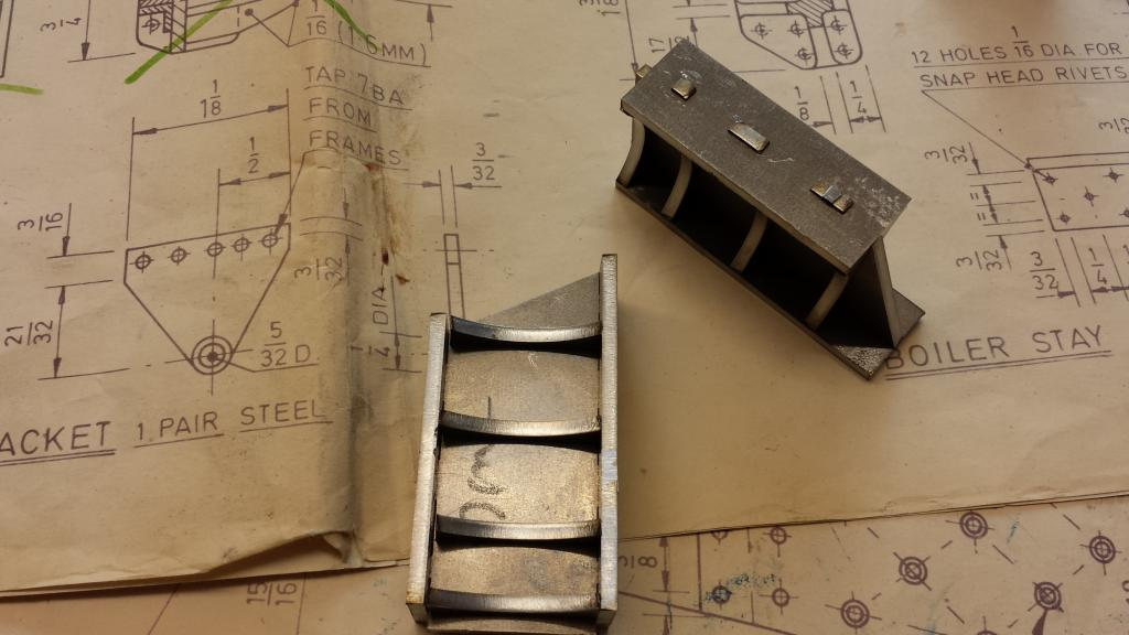
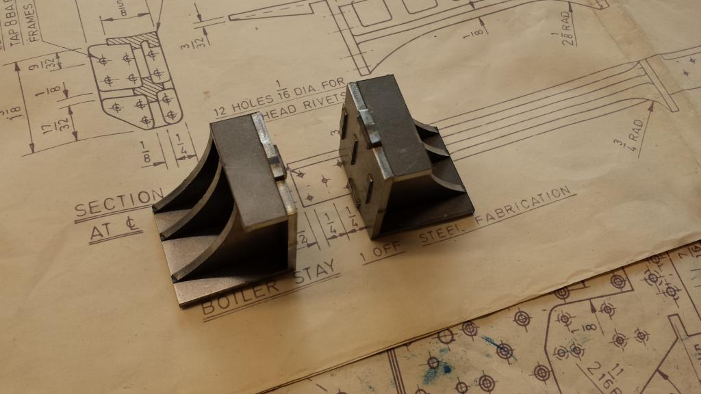
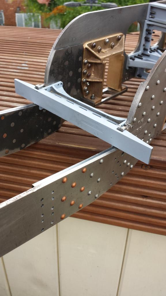
Now a few more bits and pieces, BTW the list of bits and pieces is endless. First is the boiler stay, again another part nicely laser cut by Malcolm here's the finished article after being silver soldered together and machined to size. When I was looking at the dragbox fitting I had forgotten about this stay and was a little concerned that the frames were being flexed around the rear main axle slots, my fears were soon put to rest once this little beauty was in place, the frames are very, very rigid and I still have more stays to fit, quite a few more in fact, good signs....
With the boiler stay fixed it was time to permanently fit the dragbox, stiffeners, spacers and finally the trailing frames, I will need to remove the trailing frames a number of times yet when building the cartazzi axle assembly but I think I may be able to say that the dragbox is now fixed.
NB: I found that I could remove the cartazzi axle with the trailing frames as one single unit, this helped greatly in fitting further parts later.
Here's the dragbox area so far, I have a lot more parts to do in this area though, dragbeam ends,steps,support gusset's,trailing frame stay,rear frame stay,outriggers,spacer support T beam etc etc... the list is very long and that's just at the rear..
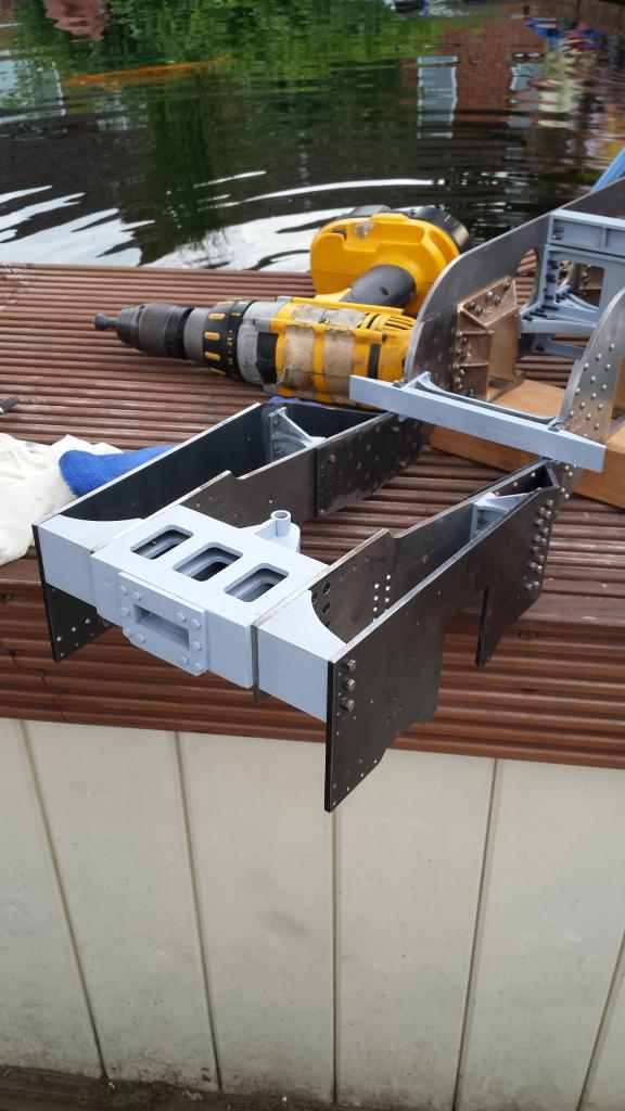
One thing to point out on the last picture is the mid-way spacers are supposed to have a 2 degree angle to match the trailing frames, the laser cut parts weren't wide enough to do this, I was thinking of machining up a small wedge to add but decided on an old model maker trick to backfill the area between the spacer and the trailing frame with JB weld. Normally one would use parcel tape between the parts so that they part easily once the filler has cured but on looking at the design I decided to join the spacer to the trailing frame permanently as it's easy to undo the other side to remove the trailing frames.
To conclude this entry we have the obligatory picture to show how things are progressing, she's beginning to look like a locomotive, a Gresley locomotive of which there are no better... yes I can hear the gasp's from Swindon now but hey I'm a Gresley man..

so what's next?...well I've already mentioned the rear, however, the front has much more. I needed to get back to the front buffer beam as there's an awful lot to do in this area. I'm going to make a slight change from the drawings too, the prototype has 4 gussets that are fabricated from steel sheet fixed behind the buffer beam and secured to the frames, which are not seen due to everything around them. I'm going to replace the steel sheet fabrications with solid steel flat bar, my reasoning is that if I do employ the usual method of holding a locomotive in a spit jig for turning I don't want to risk all of that weight being held purely by the front buffer as designed. I may well design another method altogether to hold the near 200lbs but just in case I'll beef it up where I can that's not seen. I will also take a look at the spring hangers and brake trunnion castings, these are simple machining jobs that shouldn't take too long and will add a lot more detail to the frames ready for when I get around to machining up the main wheels although I may do the cartazzi axle assembly first.... so much to do... still about 8+ years left I reckon at this pace.. better work faster, still looking on the bright side, I now have the frames erected, a milestone in itself......
NB: I had a little chuckle reading that last part re- 8 years? this post was 6 years ago and I still have many years more work to do.. I try not to think about it, 'just one small step at a time Pete, one small step'... I keep telling myself that, I don't think it helps much...:)