
Horns
There's a lot of work involved with 4472's Horns so this will be a larger entry than normal.
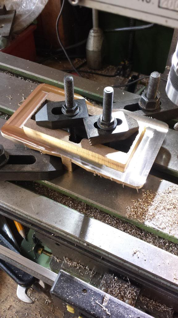
First job was to file flat the top edge of each casting so that they could then be turned over and held flat on the mill bed, next was to machine the underside ( the face that fits against the frames) down until it had a thickness 1/8".
With this done I then machined the spigots that fit between the frame slots, the drawing has these with a distance of 1.875 but the laser cut slots vary a little up to 1.877 so I machined them slightly oversize and then filed down to achieve a tight fit.
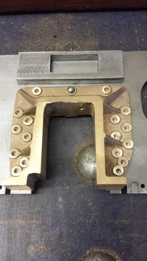
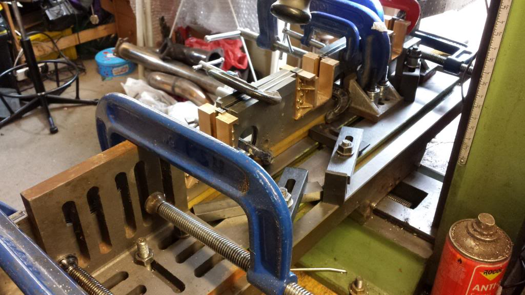
Picture shows work to this stage..
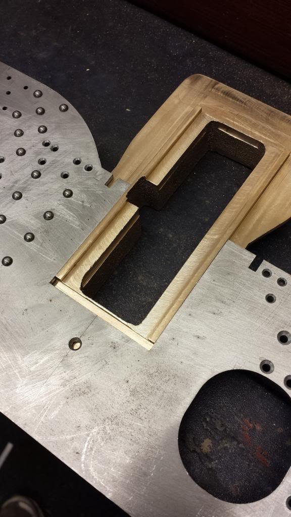
Next step was to machine the depth of the spigots down to 1/8 " from the rear face
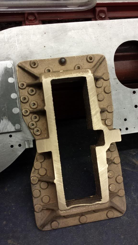
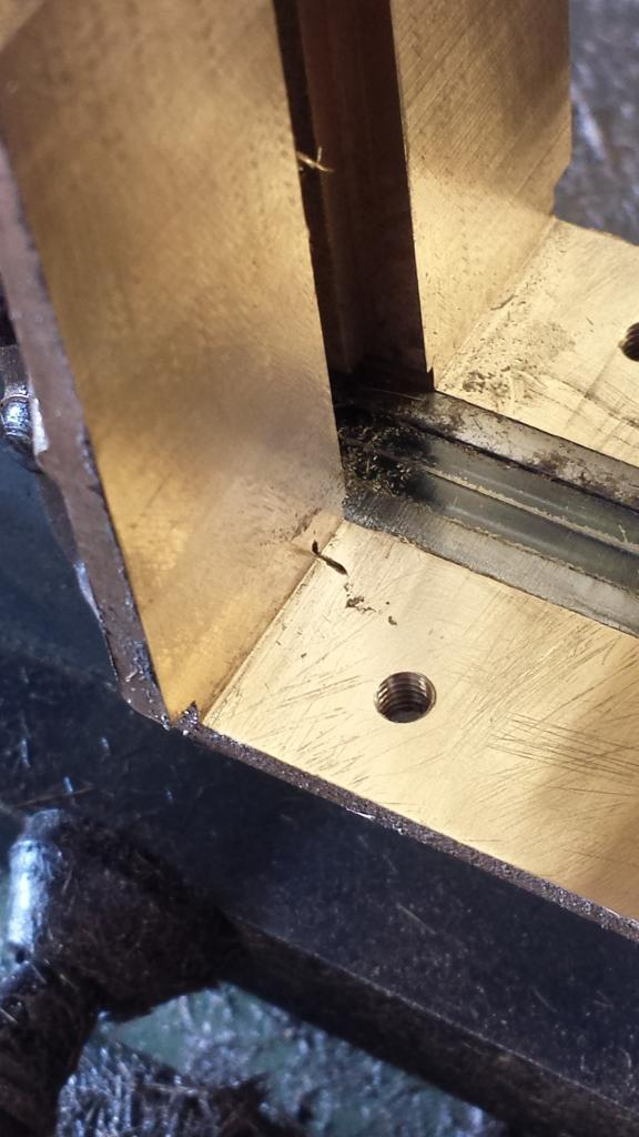
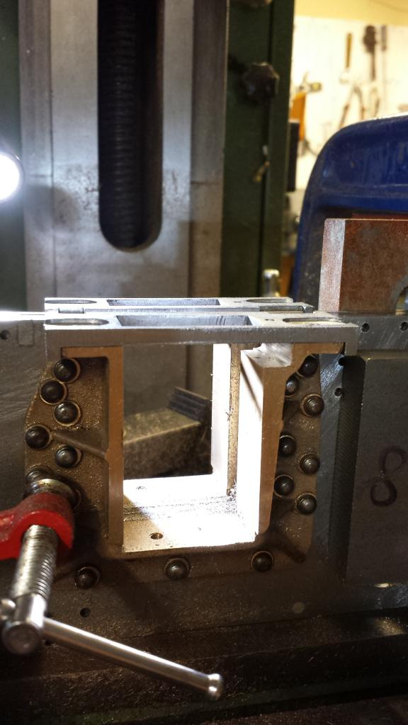
The final job for the rear face was to machine the width of the spigots at 7/64 to a depth of 3/32 which is the channel that the rear of the axle boxes run in. I have left the inner slots and tops of the horns until they are fitted to the frames and following standard engineering practice of machining both sides back to back to ensure axles are square and at their correct distance in relation to each other. Yes I know some prefer to erect the frames first and then do this, I wasn't happy about doing it that way and so selected as described.
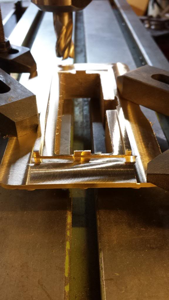
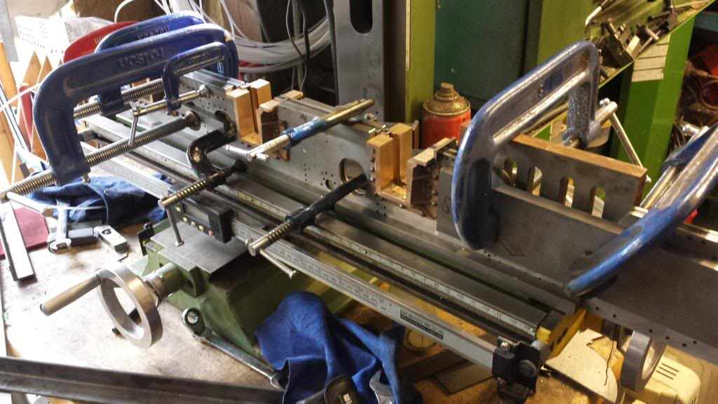
The picture shows one of the horns sitting in a slot before being parted from it's twin...
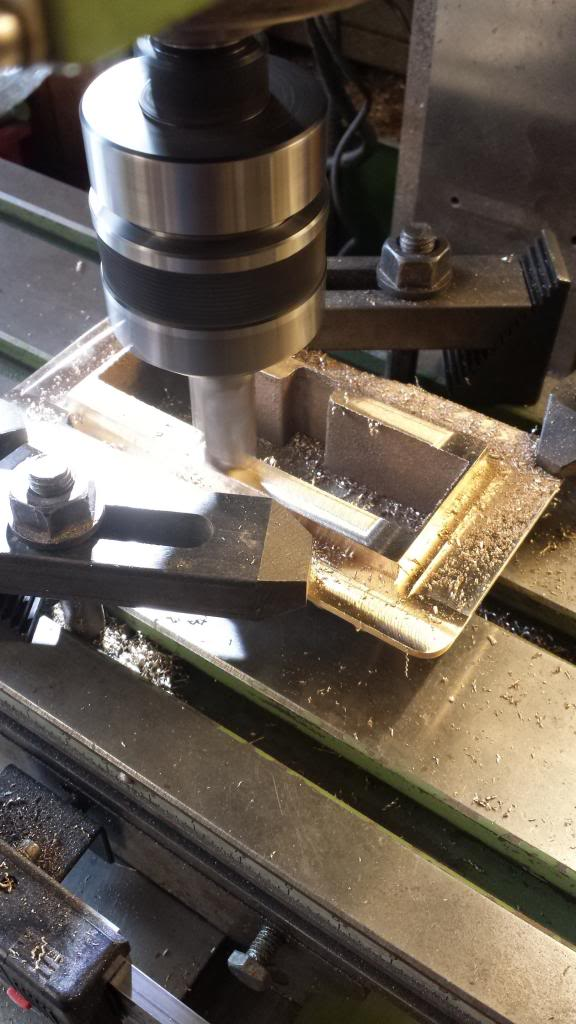
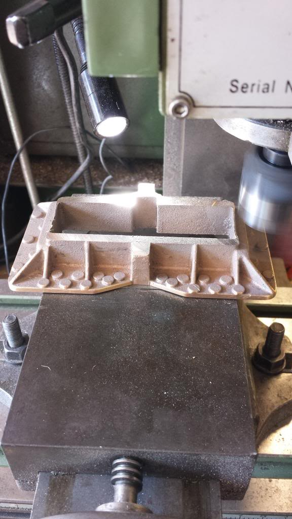
On to the front face, first job was to machine the front facing of the castings, for this I decided to use the fly cutter while held in the machine vice..
I then turned over again and went back to the other faces that had been left slightly oversize to finish off... reason for this was that the first operation relied on filing flat by hand, I'm not a great fan of relying on this on castings so played safe and left oversize to return too later when I had a perfect flat face to work from. First was the outer axle slot face machined too iirc 0.781 as shown here
and then the spigot face too 0.875
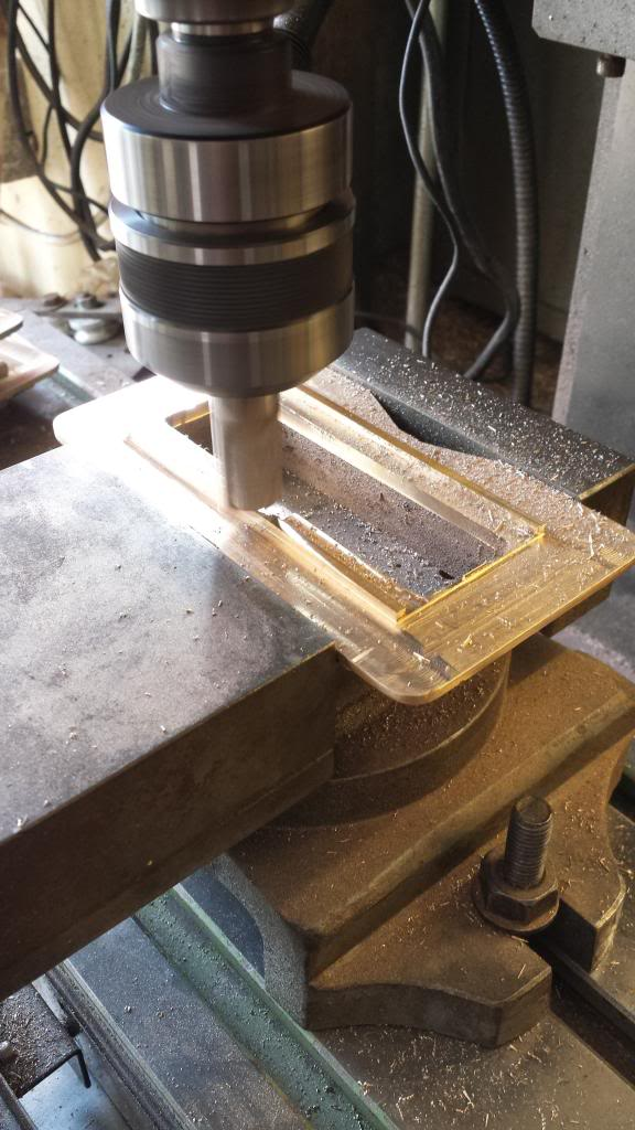
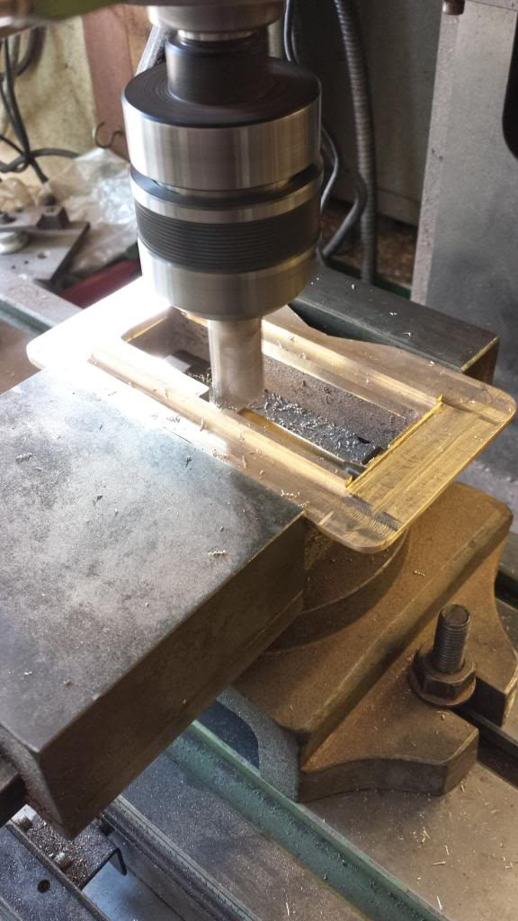
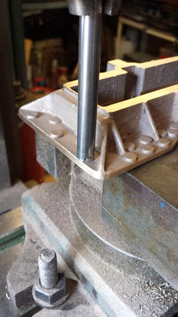
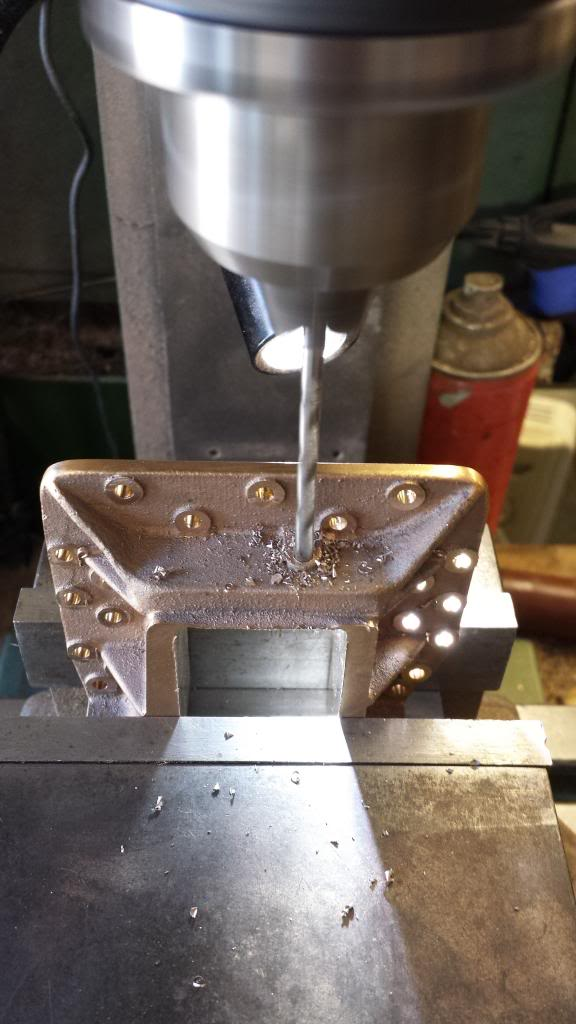
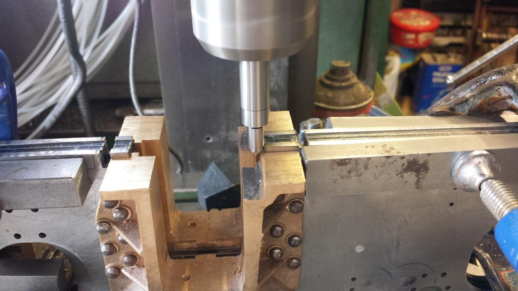
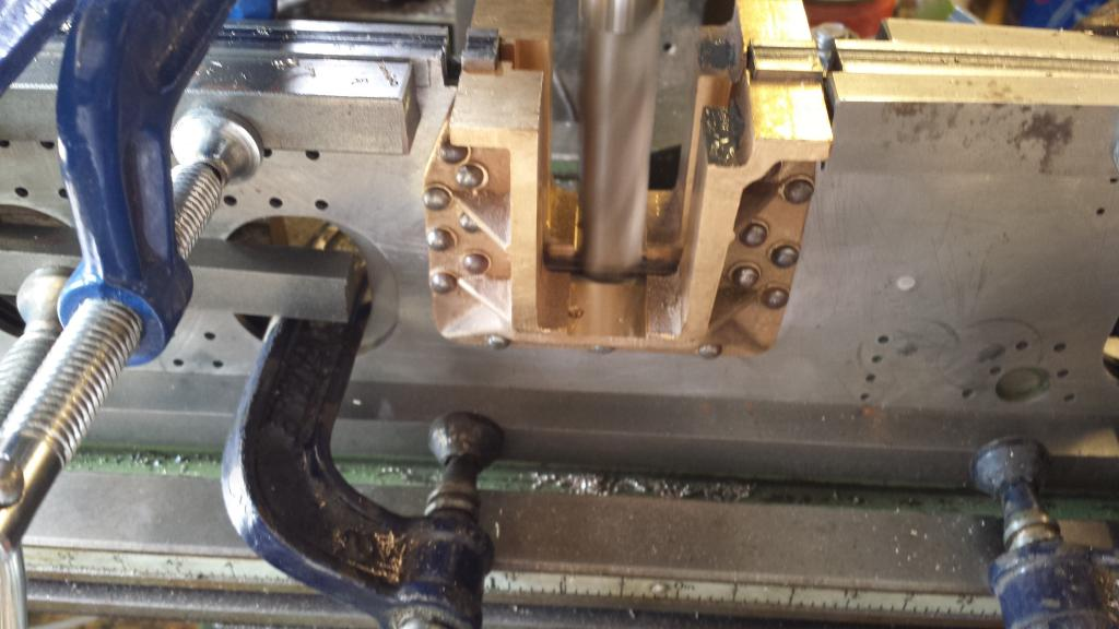
I then needed to tackle the 1/8" holes for riveting the horns to the frames, normal practice dictates to transfer the holes from the frames to the horns but these horns have prominent raised bosses and it seemed more prudent to do it the other way around what with castings being a bit varied due to their process and naturally wanting to have the holes central to their relevant boss. To help with this I made up a simple tool to help with alignment shown here in the picture, the two notches are to allow for clearance with webs/adjoining bosses.
tool in action
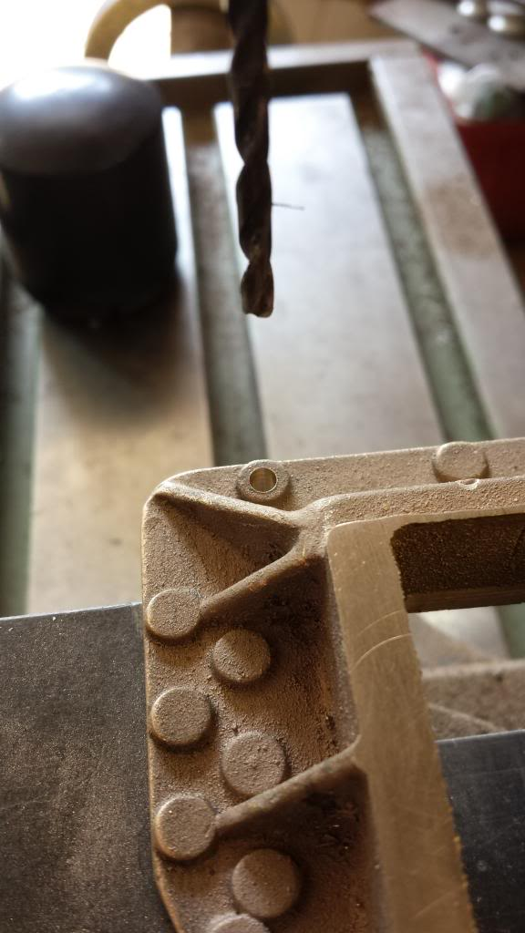
first hole drilled...close enough..
After drilling a number of holes ( so many on this model) I thought I'd take a break from drilling and check to see how things were progressing for accuracy. Picture shows the horn sitting in it's frame slot and the central rivet pushed in place. If you remember I previously drilled the central rivet hole in the frames to use for the temporary 4 1/8 spacers but also to place the horns correctly for height. The fact that the horn fitted tightly into the slot and that the rivet also fitted made me very happy as it shows that things were going to plan, also of note that the laser spot marks for the other holes just visible also mostly line up or very close although not easy to see in this picture due to the camera's wide angle.
All in all, this was a good day, I just have another few boring hours of more drilling to do before parting the horns and final details....oh well.. onwards and upwards..
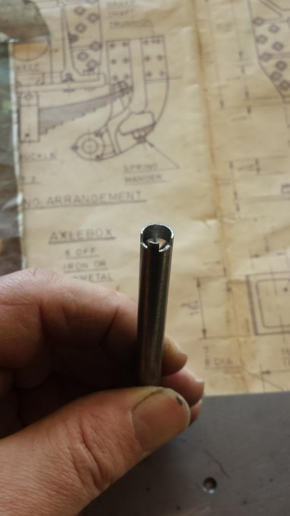
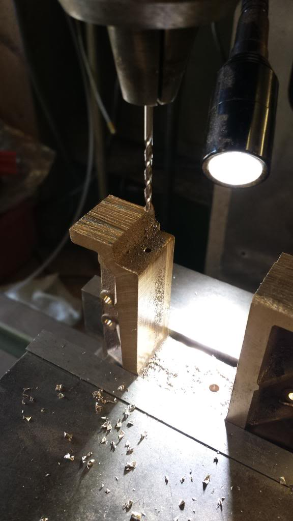
Having finished drilling all of the holes ready for fixing to the frames I then parted the horn pairs and started to drill the remaining holes for the oil feed and the dummy wedge adjusting bolts. First picture is for the oil feed, drilled number 30 and tapped 5/32 x 40 T, oil feed connectors to be machined and fitted later.
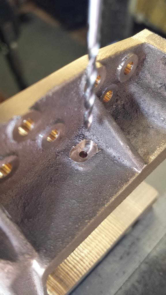
Next I turned the casting over and drilled/tapped 8 BA for the lower dummy wedge adjusting bolt hole.. on looking closer I should have spotted this hole from the horn stay.. so I'll need to pay more attention to this when I do the stays themselves. Note the bottom of the horns still haven't been machined yet, as mentioned before I decided to leave these until the horns were riveted to the frames and will do this when the frames are fixed back to back for machining of the axle box slots.
I then tackled the remaining wedge adjusting bolt hole on the side of the horns, this has a small recess as seen here, hole as before is tapped 8 BA.
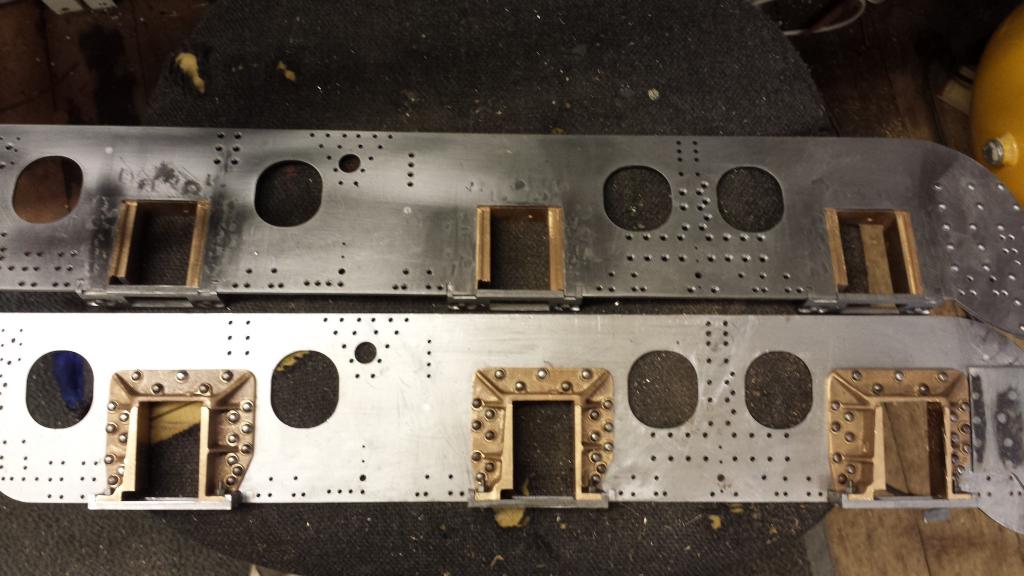
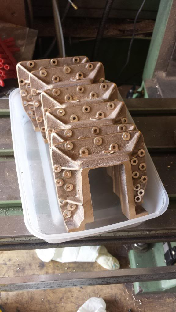
A picture of all 6 horns ready for fitting to the frames, I still had a fair bit of work to do before fitting them to the frames in drilling all of the remaining holes into the various stretchers which so far only had a few location holes completed. I also needed to do this first as the 3 temporary 4 1/8 spacers used to keep the frames aligned, borrowed the central holes for the horns and thus were not be available once the horns were fitted.
This was a solitary picture at the time as there was a fair bit of work involved in getting to this stage and I'll give a few more words than usual to explain it, I had fitted the horns although only held by one rivet so far, I still needed to machine the bottoms, just me wanting to check all was as it should be with other associated parts first, the main part being the horn stays. These are relatively easy things to make but need careful thought to ensure they line up properly. I had Malcolm (MEL) cut these for me from 8 mm steel plate, the plates are slightly over size for machining with the rectangular slot being slightly undersized. This saved a lot of work but does add it's own problems, that being finding a datum to begin with. So first I machined the 8 mm down to the required 9/32 thickness, I then machined the ends to match the outer slot spacing in the frames, I left the width for now. Next I tackled the slot, as you can see the slot is offset on both axis, I started with the long slot edge closest to the outside edge of the stay and filed this square removing the laser cutting marks, thankfully not too tough. Next was to file the opposite edge until the slot was .562 wide, equal amounts were then taken off either end to arrive at 1 5/16. I then tackled the outside dimensions for the stays by first machining the long edge furthest from the slot until it was 0.203 from the slot edge, final cut was the other side for the width of 7/8
Little more progress made here....Horn stays nearly complete.. picture shows two of them sitting on top of their respective horns, they are sitting higher than they should as the horns still need to be machined, plus bottom and gap. Once machined they sit such that they are proud of the bottom of the frames, the end corners still need to be radius'd but I'll leave that until the horns are finished, reason being that the radius stops as the end enters the frame so it will be easier to gauge this once they are sitting properly.
Now going back to the dummy wedge bolts that if you remember I had mistakenly drilled into the horns instead of spotting through from the stays first, having now looked closer at the design I note that the dummy bolt sticks up from the horn, goes threw the stay with a thin nut either side to lock in place. Since these are only dummies I'm thinking of forgoing the threaded section into the horns ( filling previously drilled holes)and just have the bolt touching the bottom of the horn instead, this will still look as it should but with the bonus of not having to disturb this bolt when removing the stays, just makes life a little easier and even if someone climbed underneath to take a close look it would never be seen anyway.
NB: Considering now how often these have been removed during construction this was a very good move...:)
Another slight deviation, this time with the two recessed areas around the stay bolts, these should have 4 flats sides instead of the 3 that I have machined, again it's down to being a simpler machining exercise using a larger 11/32 cutter in one move rather than a 1/8 cutter in a rectangle, I still have the outside flat edge by running the cutter off the edge until it gave a radius similar to that on the drawing.
last picture to show all 6 ready for riveting and then awaiting the final machining of the horns .
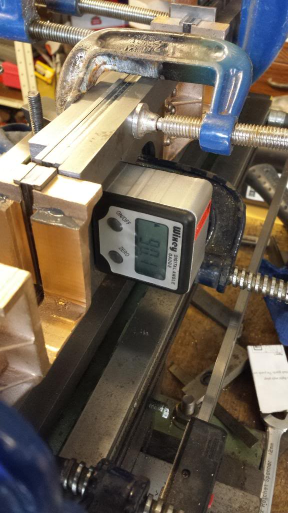
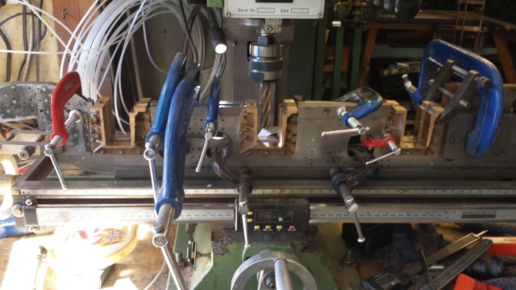
After a marathon riveting exercise I was ready for that most important of jobs, machining of the slots. I spent an entire morning setting this lot up ready for machining, it's rigid, very rigid and is using everything that I have for clamping the frames to the bed. 3 angle blocks which I fixed a steel square bar too and clocked it to be true, decided to use these instead of right angle as I don't have the ability to easily hold a long length to machine square in one setting, time to get another vice I thought.
I cut up a set of reeves spare frames (xmas present from the kids) to clear the rivets that hold the doubler plates. These had one of the lightening holes in the wrong position making them useless for their purpose. I used a couple of reference holes that were also cut through the spare frames to keep the two frames aligned correctly. This has given me a very rigid 4 piece 1/2" steel laminate before any support had been added.
The frames were then rested on the bed and held to the angle blocks, more steel bar was added for extra rigidity , two long bars along most of the bottom edge and others at various places held tight with clamps. The frames were then checked to be level with the bed and upright. I couldn't get a perfect 90 degree upright position for the frames. Could be due to the frames being filed after riveting of just not flat to begin with, not wanting to chase my own tail any longer I've settled for the 90.1, length ways is perfectly flat which to me is of most importance.
NB: IN hindsight I wonder if this was just because they were laser cut and thus the edges may not have been perfectly square? whatever the cause, it had no ill effect and invisible to the eye.
Anyway, a few pictures to show my final setup
first picture... closest I could get
View from the rear
finally view from the front
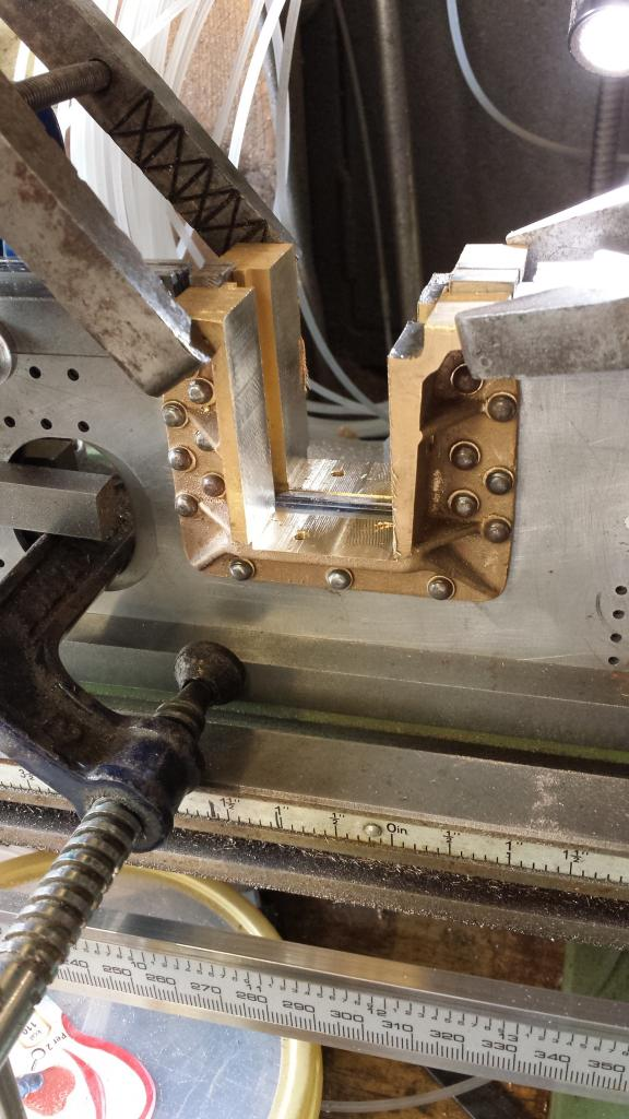
Using a brand new long series 5/8 cutter I made a start on what for me was a very important machining exercise, probably the most important so far in the build at that stage. The cutting flutes (4 off) have a cutting length of 2 5/16 so big enough to cut the entire horn cheek in one go without needing to step machine. First job was to find centre point for the crank axle which was then my datum for all 3 slots.
Having previously checked the accuracy of the laser cut slots it was easy to use them as my starting point, find the two edges using an edge finder, plot them and note centre, this is my datum point from which all others were plotted from.
Picture of edge finder in action, rpm set at 1000+...note it's running along the frame slot, not the horn.
With the cutter set at centre point I machined the centre down to about 10 thou above it's correct size for roughing out, picture shows a centre channel cut .
this picture shows the centre horn cheeks machined, they were at this stage 60 thou undersized for width and about 10 thou for depth, plan was to machine the other two slots to this size for the roughing out stage, then re-find centre with the edge finder again, just in case of any creep during the machining. Should then be a simple job to machine accurately to their correct size - 0.5 thou for final polishing of the horn cheeks.
I did a number of checks using various calibers just to keep an eye on things, after finishing roughing out the centre slot I re centred the cutter, moved it on to the next axle centre using the scales to a position of 7.687.5 or 7 11/16", it was very reassuring to measure the cutter's position to find that it's bang in the middle of the next slot.
Well that's the three slots all roughed out, I've left 10 thou on each surface to be machined using another new cutter. I have reset the cutter back to the datum/centre point ready. The cutter is certainly showing signs of being blunt, a slight high point has begun to show in the middle of the slots, so the centre of the flutes are blunting quicker than the ends. It only took about an hour to finish the slots with the new cutter and then I moved on to the height that still needed machining down to size for the horn stays to fit correctly, Ionce that was done I could then spot and tap the holes for the horn stay bolts, which will needed turning up first.
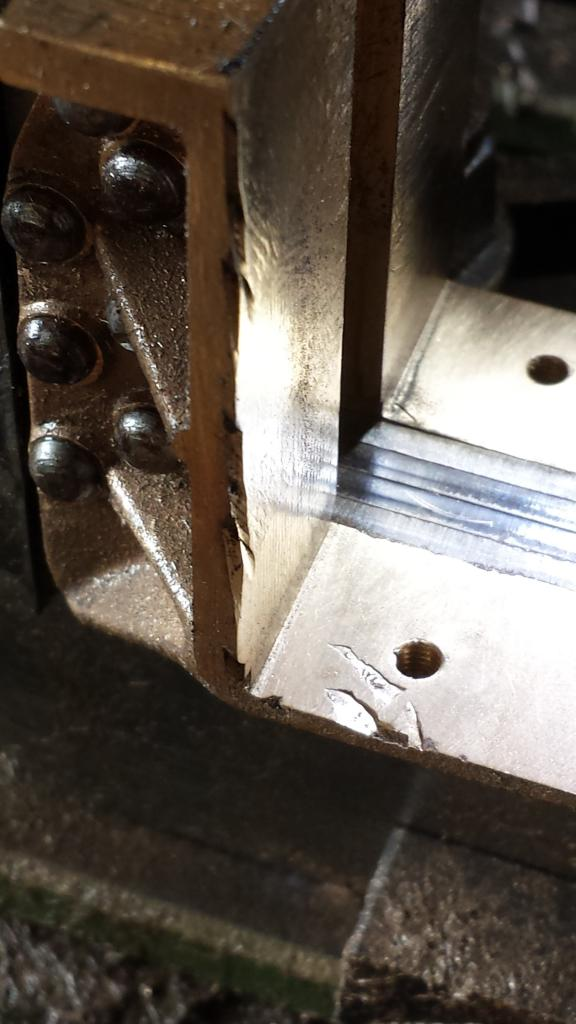
It was a mixed day when I originally wrote this section... a few problems, one of my own and one not but got there in the end, rear slot is now slightly larger than required, about 2 thou this was an error by me (other two at 1 thou undersized)... not sure what happened but the cutter dug in on the final cut. Either I turned the wrong dial, cutter moved (unlikely being in an auto lock) or the job itself moved. End result was damage to the rear face and to the top as shown here, requiring an extra small cut to clean up. Before moving on to the next job I rechecked my datum, it hadn't moved so I continued although a little angry with myself and a lot more wary.
NB: I don't make many mistakes and the parts in my scrap box after 11 years can be counted on one hand but this one could have been costly, luckily someone was smiling on me that day...:)
Next problem this time not of my own was a blow hole in one of the castings... not a big deal as it's mainly on the top so not a running surface but it does beg the question, if there's a fault on what's really a simple casting what are the others in the pile going to be like? If you guys remember the bogie swivel also had issues, I just hope there's nothing wrong with the cylinders... fingers crossed..
NB: I later discovered that there was indeed a small blow hole in one of the cylinders, again, someone was smiling on me as it was not in a critical place, more on that when we get to the cylinders.
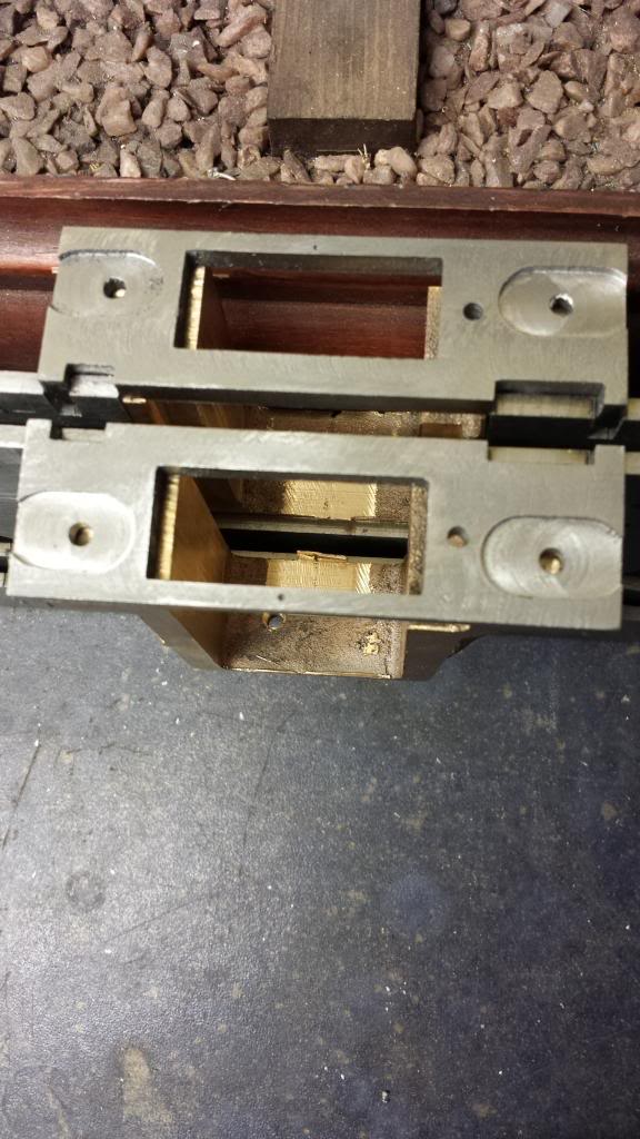
Anyway I continued without any other issues to complete the horn machining, I then fitted the horn stays although haven't spotted the securing bolt holes through in this picture yet, that was the next job on the list.
It was nice to note that the horn stay slots line up with the horn gaps as required, this being the first time that they had been assembled together. I still needed to curve the corners of the horn stays as per drawing and also add the dummy wedge bolts and nuts which will now not go through to the holes in the horns as mentioned a while back, holes previously drilled for this having been filled and the recess for them now machined to finish with a 3/8 ball nose cutter.
So as I said it was a mixed day but nothing that couldn't be sorted as the build progressed, I just hoped that these type of days were few and far between...
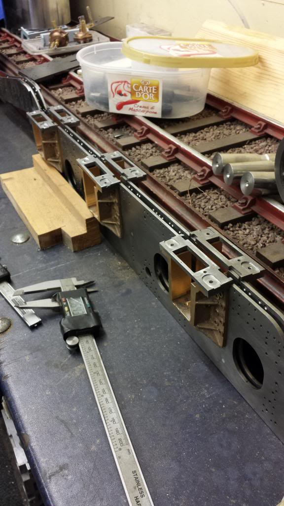
This last picture for today's entry is just to show the frames as they were at this stage. having reached this point I was biting at the bit to erect the frames but still had many more days/hours of work to do first, hundreds of yet more drilling and tapping of holes for one...:)
