First a few notes on what I'd been up to prior to this latest entry, treat it as what happened behind closed doors.I split the frames and countersunk the relevant holes so that the screws sat correctly within them, fixed rivets into the temporary holes that had been used to hold the two frames together while the copious amounts of holes had been plotted and drilled. Before doing this I also held the frames together to drill the upper buffer beam holes in their correct position and filled the wrongly drilled holes with suitable rivets which were then filed flush.
At this point I decided it was time to fit the doubler plates, these fit to the inside of the frames around the firebox area, I first needed to consider the fact that the frames also bend in towards the dragbox at this point and that the rivets used are round head for the outsides which would be crushed if riveted first before bending. My way around this was to rivet the rear section of the doubler plate only and then bend the section to shape as I was worried that if I riveted the whole plate and then bent it the rivets would not only get damaged but may also be forced apart.
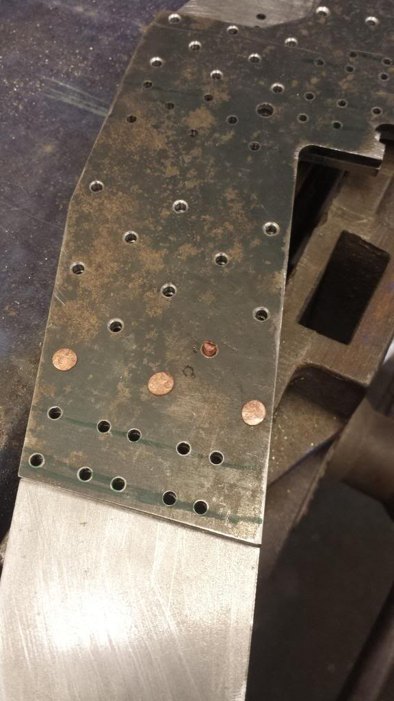
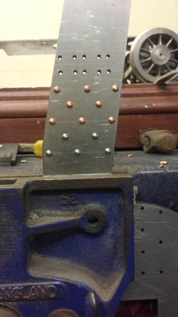
First picture shows the first few rows of rivets, I began with copper at the rear and then used soft iron as I was short of the soft iron suggested by Don. Before starting a few rivets were placed in various holes to ensure all was square.
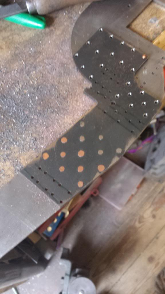
This rather poor picture (my fault) shows the rivets completed for the rear of the doubler plate and filed down, I've left them a little proud at this point in case there was any movement during bending, as it turned out there was no perceivable movement of the plates.
I now needed to plot the correct position for the bend which is 4 1/2" behind the rear coupled axle centre. Here I reused the jig that I had previously made for marking out the crank axle centre , for plotting the 7 degree angle required for the centre cylinder incline.
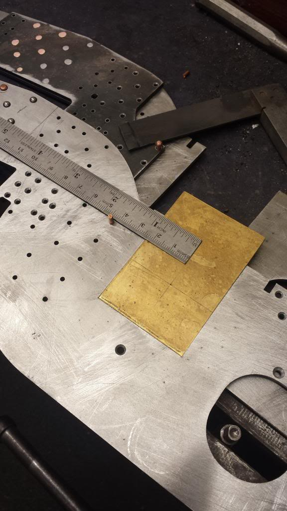
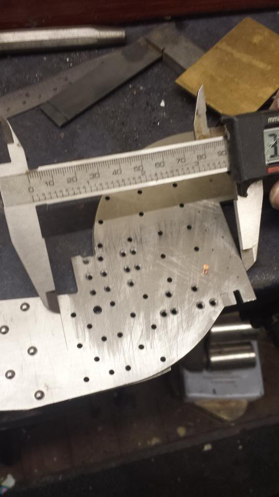
With the position for the bend marked I used a vernier to take an accurate measurement from the rear axle slot so that i could duplicate the mark for the other side.
Next job was to place the frame in the vice along the marked line and do it up very tight, a square was also used here to check that the frame was sitting upright.
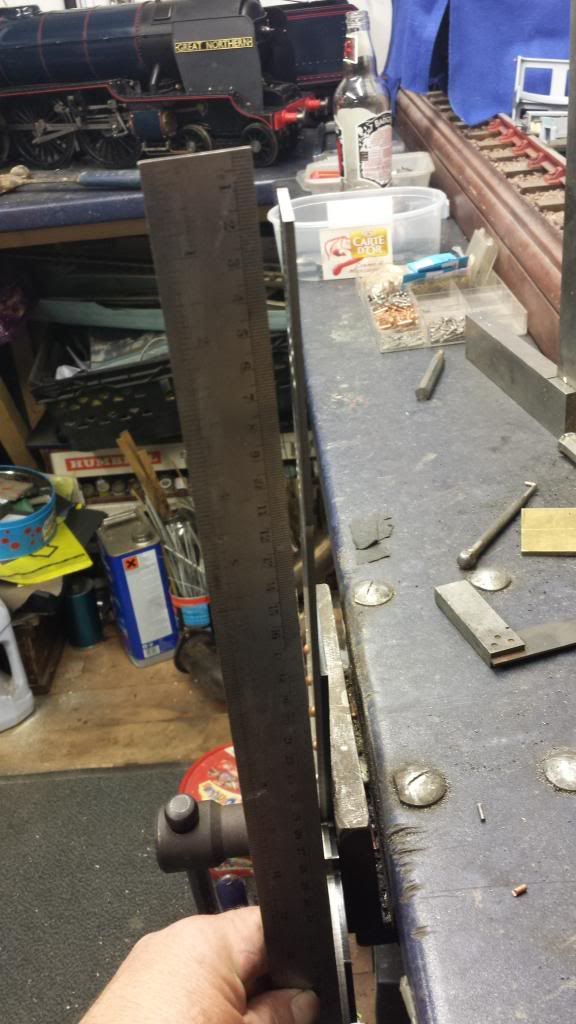
using a 2 lb club hammer and a piece of wood the frame was persuaded to bend to it's correct position which is 5/16 in from upright or parallel when assembled and viewed from above. As can be seen a straight edge was used to check the distance moved, you'll have to take my word for it that it does measure 5/16... I only have two hands after all...
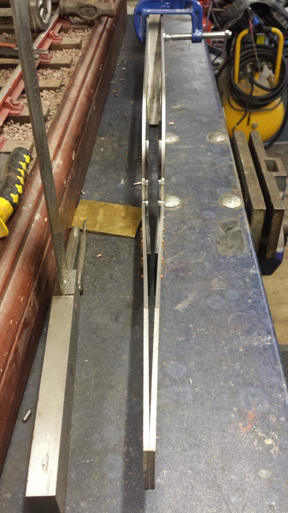
Just to check that all was going to plan I held a 5/8 piece of steel bar between the frames and clamped them together, the method used to form the taper worked very well as can be seen in this picture.
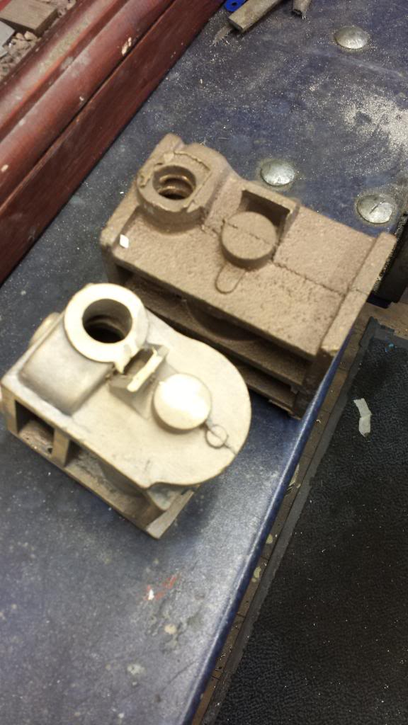
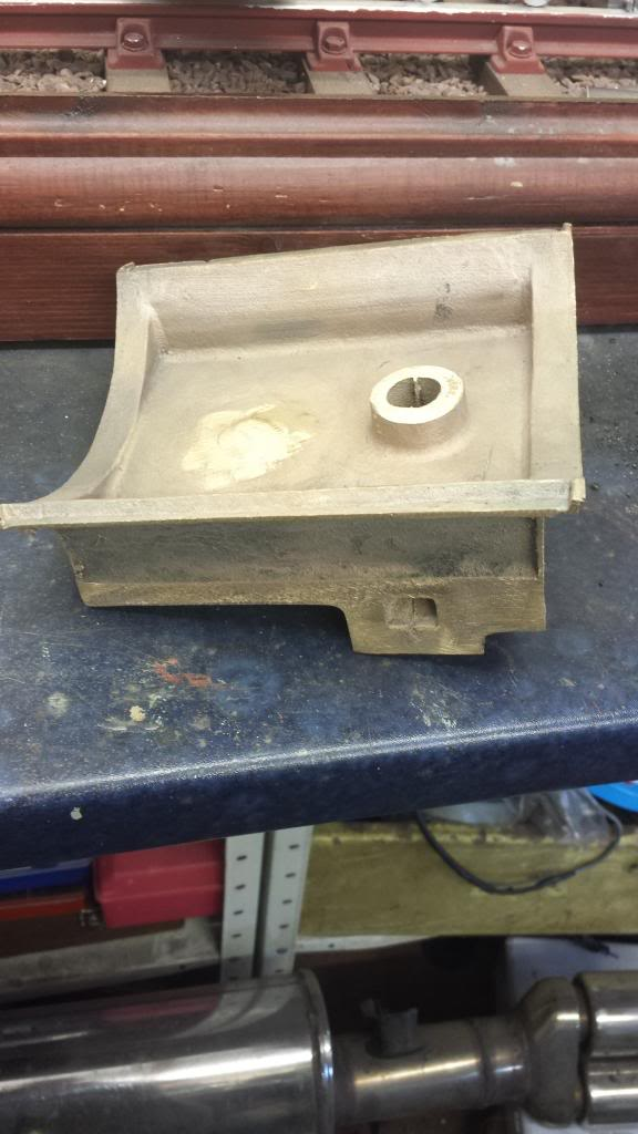
These next two pictures are just to show some castings which arrived about this time and why i'm showing them now. below is the very nice saddle, cast in Gunmetal.
And here is 2 of the 3 cylinders, I will share a lot of detail when describing how I machined theses, being blind bored they are not your usual cylinders to bore.
These again are cast in bronze, I had considered using Cast iron to safe a few pennies but when inquiring with Reeves as to their cost, discovered that there was no saving on these due to the high amount of 'rejects' in cast iron from failed casting. And so I forked out the near £1k cost for these beauties and beauties they are.. more on them later.