
This entry has some involved parts, the buffer housings for one although life was made much easier thanks to Malcolm's laser cut parts, he also drew up a guide which I used with a small modification to form the curves, more on that later. I'll begin with the Buffer Beam stiffener brackets of which these parts are just the beginning and they don't stop with this entry.
There are an awful lot of components that make up the Beam and it's associated parts which seem to follow full size practice very closely.
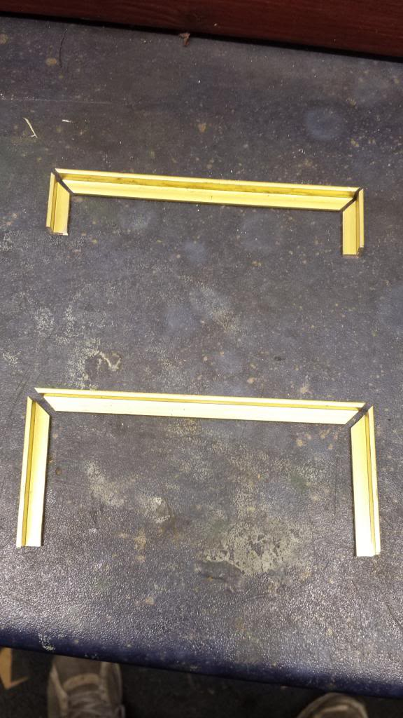
Here are the first parts ready for silver soldering, fabricated from 1/4 x 1/4 x 1/16 brass angle, these fit top and bottom of the beam and as can be seen of different length tails.
next we see the beam stiffener brackets fitted between the frames, as per usual they only have two holes drilled and tapped for now, also they still need cleaning after soaking in the acid.
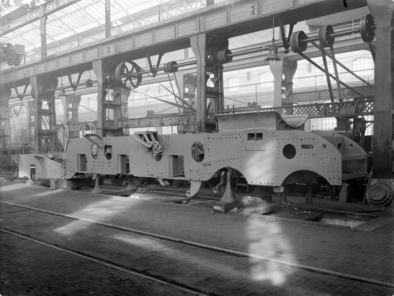
And to show how we've doing, a picture showing a set of frames being erected at Doncaster 1928, not too many differences and those that are there may be due to later mods when Don was working on these himself. The various stiffeners seen along the length of the frames are all covered in Don's notes and thus all will be on the model and there's even more than shown in this picture. It won't be long before we get to some these in this blog

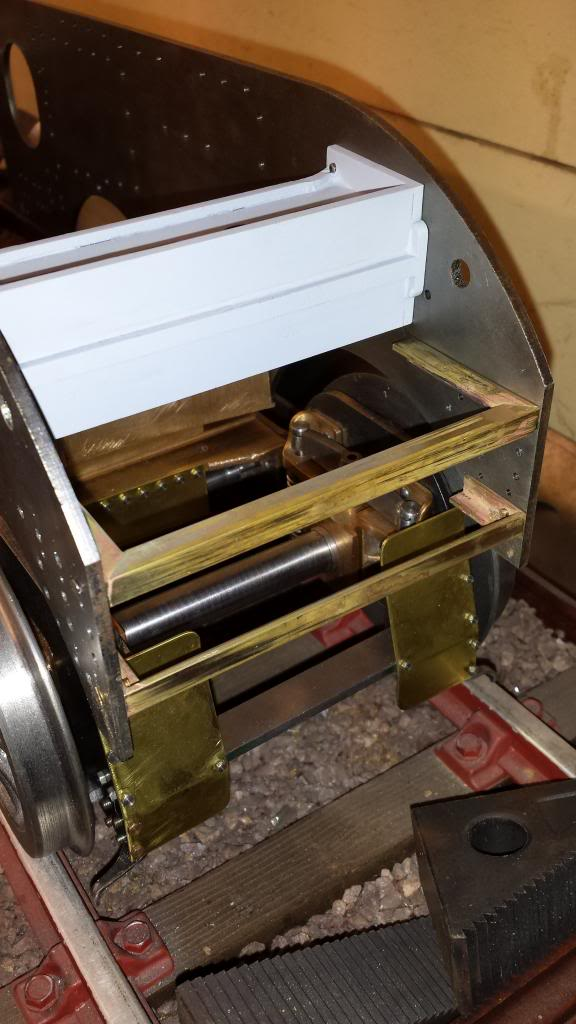
Another one of the stays, this shows the boiler intermediate stay fitted to the frames on top of the star stay... now this is certainly different to 4472 today as the star stay is taller and comes up to the top of the frames and thus there is no intermediate stay as shown here.... again this may be due to changes over the life of a Gresley pacific or a one off on Flying Scotsman today? The works drawings of 1470 in 1922 show the arrangement as seen here.
Continuing with the front end here's the front buffer beam having had all or it's holes drilled and csk where needed.
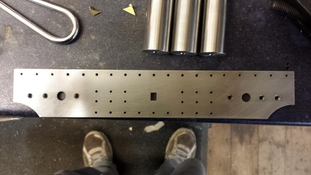
It was then time to check the fit of the two stiffener brackets while loosely held on the beam with the frames and here I discovered that I had got a row of holes slightly out of place, at the time of doing these particular holes i was a little uncertain about their placement due to the curve of the frames at this point. Looking at it now if I'd have paid a little more attention I wouldn't have had this problem... well it's not really a problem just means 4 holes on each frame need moving up a little. If I had realised that the two brackets sat exactly top and bottom of the beam I'd have had a reference point to check... oh well live and learn..
Anyway I needed to get the beam exactly central to the brackets so I marked the centres of both the top bracket and the beam ( this was already marked), aligned the two together and used a tool makers clamp to hold in place. I then held this in the vice and checking that all remained true began to drill through the beam holes into the bracket, after each hole had been drilled a rivet was put loosely in place to keep everything aligned. With the top bracket held in place with the rivets but still loose I then used a square to get the bottom bracket into it's correct position and also drilled through as with the top.
Picture shows the beam being checked that it was level and square with the bottom bracket only being used to hold it in place. If you compare this with earlier photo's you'll see that the top bracket is now higher, the 3 other rows of holes all line up correctly with the frames... I must have been away with the fairies for a few minutes... I think the incorrect holes were the last ones that I did too...lol
This picture shows that the beam had now been properly riveted to the brackets and the csk rivet heads have been filled down, when the riveting for the beam was been completed I filled any marks with JB weld so it has a nice smooth finish.
Well I mentioned at the start how much work was involved in 4472's beam assembly but even though I have the drawings I hadn't fully appreciated just how much there was. The six remaining holes seen in the centre of the beam are for 4 gussets that will also be riveted in place and then be bolted through from the frames too, this I only learnt today, still at least I now know what all the holes are for. At this stage I still have two more pieces of 1/4 x 1/4 x 1/16 brass right angle to fit to the top outside edges of the beam, and then the spring housings which are lovely things but very involved. More on those at the end of this entry, one thing is for sure, this buffer beam won't be falling off in a hurry...
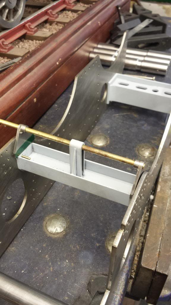
I then warmed myself up a little on my silver soldering skills with the vacuum bracket being a much simple part to construct than the spring housings. The picture shows the kit of parts as supplied by Malcolm, a fairly easy part to make but it would have taken some time to cut out these shapes by hand and also been a little bit more involved in holding the parts together for silver soldering. this is where the 'slot and tab' method comes into its own.

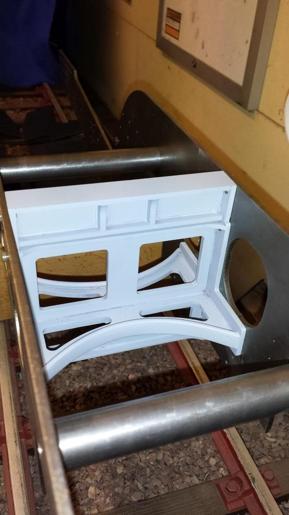
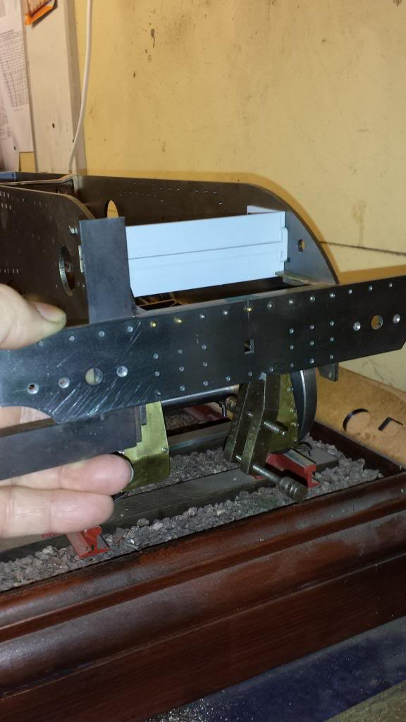
And here's the end result, the vacuum cylinder stay shown already mounted to the frames. The two brackets sitting in place and a length of 5/32 bar running between them and the stay to ensure all lined up.. Once I was happy that all was as it should be, the brackets were clamped in place and the holes spotted, drilled and tapped.
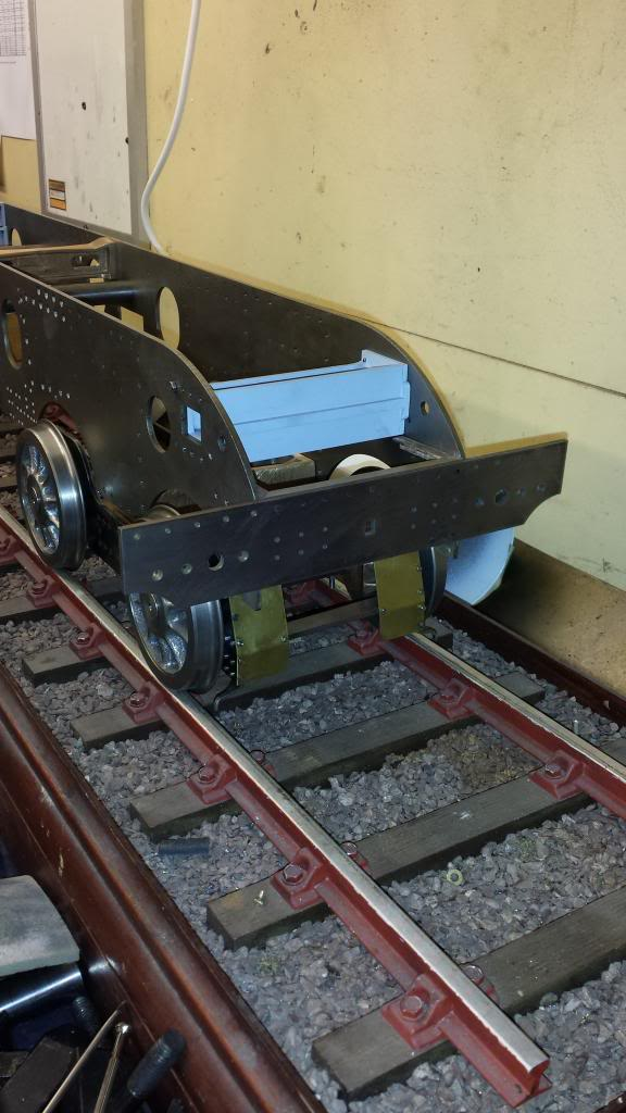
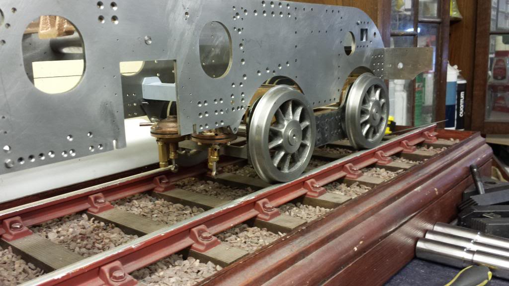
Once the vacuum stay and it's brackets had been fitted I temporary fitted the vacuum cylinders to check for clearance with the front bogie. Picture to show how close the cylinders are to the bogie although they look clear enough to avoid any fouling. The cylinders have only been loosely assembled purely for this test.
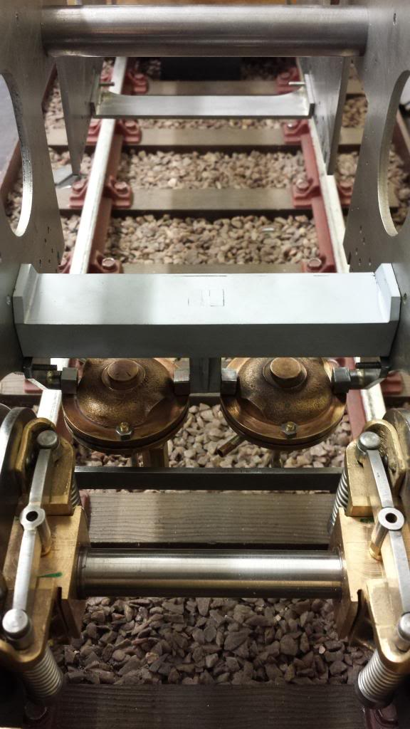
Final picture of the vacuum stay arrangement to show the overall positioning of the vacuum cylinders in the frames.
Now we come to those lovely spring housing affairs, another one of those very prominent items seen on a Gresley Pacific....
First pic to show the items as received from Malcolm, these are the very substantial Buffer Housings which are very much to the prototype design. they not only look good when fitted, they also add a lot of strength to the front buffer beam.
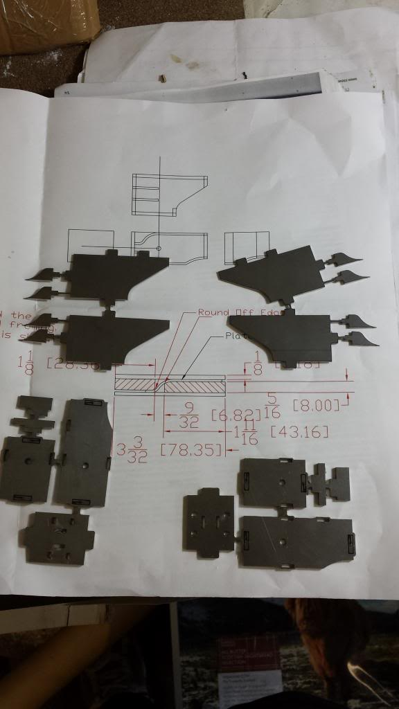
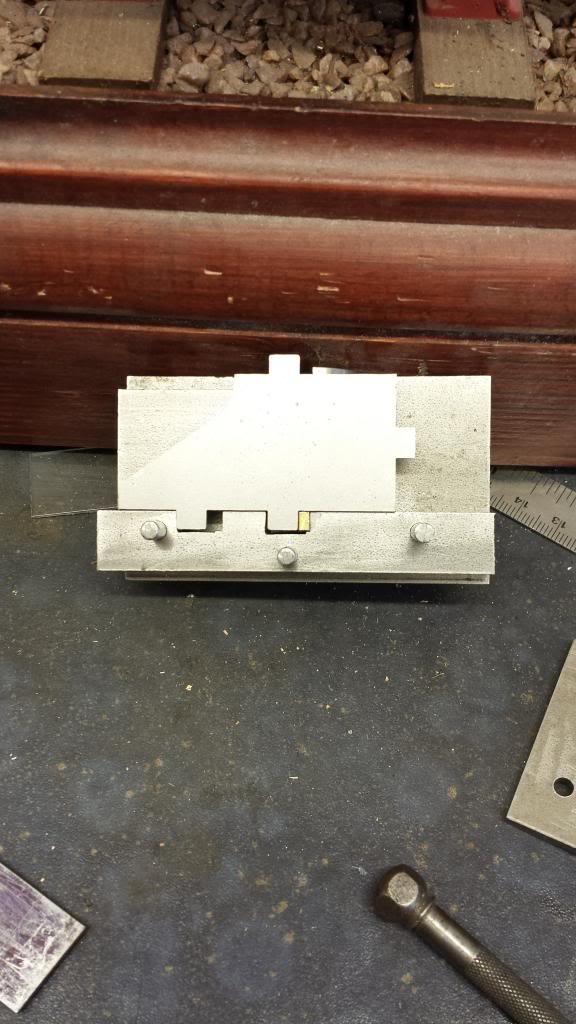
There were a number of curves that needed forming which required a forming tool to be made, picture shows the tool along with the drawing that Malcolm has provided with the parts. I followed Malcolm's drawing in as far as sizes are concerned but modified it with the steel quadrant insert seen here. This was cut from some 7/8 EN8 bar, above the tool can be seen a test piece of steel strip of the same gauge as the housing to check the curve was correct. BTW, it was decided to use a thinner thickness of steel for the curved sections than drawn which made life much easier. The jig was built from stock materials that i had to hand in the workshop and built to my own design.
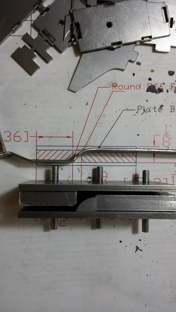
next picture shows one half of the forming tool with one of the parts fitted ready for forming, the slots seen were used to hold the piece in it's correct position by making use of it's tabs and thus getting the curves where they needed to be.
And here we have two parts formed, note they are opposites as we need a top and bottom and also a left and right hand housing, I marked the four parts required to ensure I formed them the correct way around.
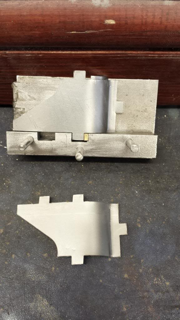
In this picture we have one housing with it's main components assembled and the other with the bottom plate shaped and dry fitted to the front section. The curve nearest the camera follows the shape of the front buffer beam cutout and was formed by hand on the rollers.
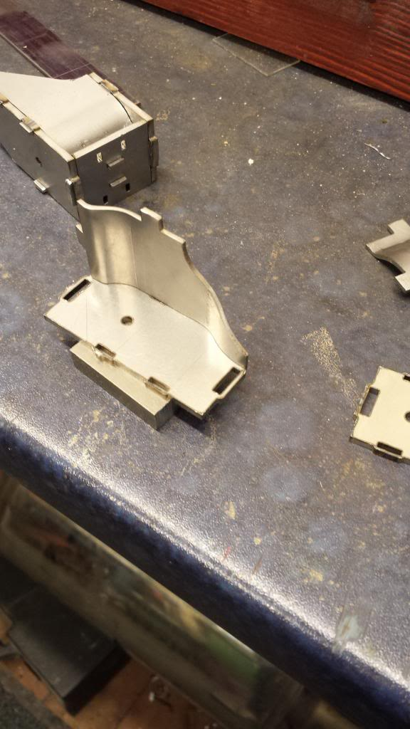
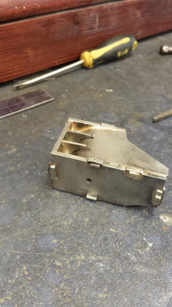
here we see the two housings fully assembled ( minus webs) that are ready for fluxing up and silver soldering.
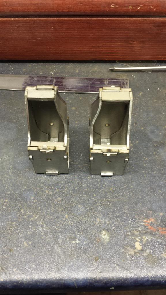
After being silver soldered together and cleaned up the webs were checked for fit, these were soft soldered using a high melt soft solder as IMHO they do not need silver soldering being tucked away out of sight and harms way. Note the tab that hasn't penetrated with silver solder yet, this was sorted before any soft soldering was done.
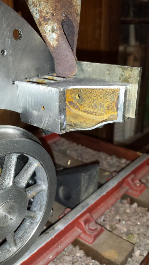
A Final picture of the housing after it had been machined square and held in it's correct position( NB: the holes half hidden are the ones that I drilled wrongly for the top buffer beam support, you can just make out the new positions marked ready for drilling), I will transfer it's mounting holes once the frames have been parted as it's not possible to get a proper alignment as it is.
I'm very please with how these turned out and even more so when I reached the stage of fitting the buffer stocks and heads, again these are also very much prototypical, more on those later.