Most of the parts seen in the next few entries will be laser cut parts as supplied by Malcolm High of Model Engineers Laser. these will begin with CAD work drawn by Malcolm and as we progress the CAD work was then drawn up for me by John Baguley and cut by Malcolm, I am very grateful to both gents.
First up is the simple frame stay that sits along the bottom edge of the frames below the expansion link, these parts are slot and tab construction although the bottom slot areas need machining off once they have been silver soldered together. For future builders there are two sizes for this stay so check which your loco had for your chosen era, as I'm building an A1 the smaller stay was required. Don does mention about possibly needing two of these stays but his words say more details given later.
NB: I can now say that if building an A1 you can ignore needing another one of these particular stays.
Here we see the frame stay just after being silver soldered.
And now in a finished state after first being machined to width ( 4.125"). I decided to help ensure all stretchers fit correctly to drill just two datum holes , one each side following the drawings for their correct positions so that each stretcher sits where it belongs. All other holes were transferred across in a mass drilling session once all stretchers have been made.
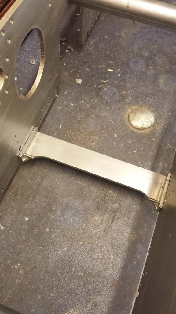
So, here we have the first stretcher made and part fitted in it's correct position with just temporary bolts.
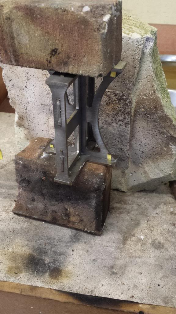
The next stretcher that I tackled ( 2:1 gear stay) was more involved and couldn't be fully completed until much later as the position of it's fulcrum and associated PB bearings are critical for the proper operation of the 2:1 gear for cylinder timing. However all other parts could be made and it's correct position on the frames be ascertained.
I silver soldered this up in 3 sessions, first was the basic shape, front,top,bottom and sides, the picture shows the assembly after the second stage when the back curved section has been added, a lot of heat was needed here as the steel is 1/8th thick.
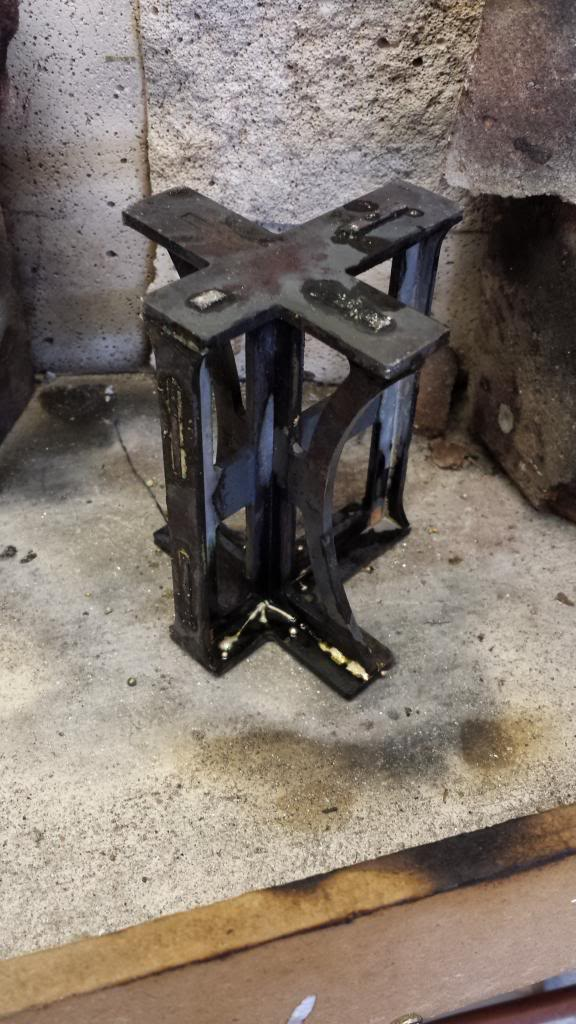
The third session involved silver soldering a 1/8th strengthening strip that's required on the front plate, I didn't have any 1/8th square steel at the time and so used 1/4" and machined it down after cleaning up as seen here.
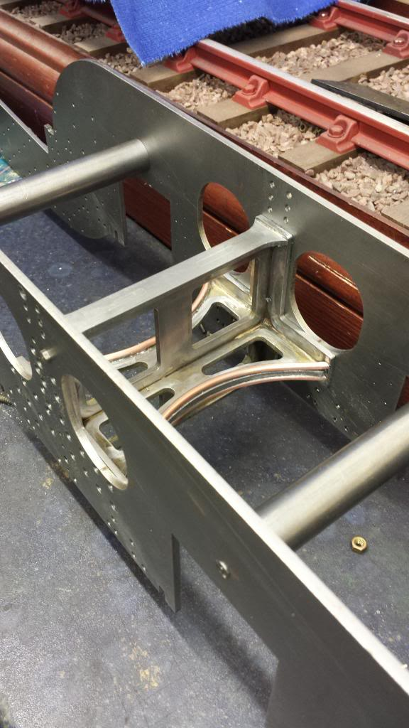
Following the same principle as with the frame stay I drilled one hole each side for holding the 2:1 gear stay in place. An aid in this case to ensure the stay sits were it belongs was the use of a suitably sized piece of steel that closely fitted the rectangular slot in the frames and the corresponding slots in the stay, once pushed threw trapping the stay between the frames it wasn't going anywhere. The height was set by first ascribing a line along the top edge of the stay sides to show where the bolts go through and then to mark another line across it when sitting in place to give the correct position for the two holes. This tunnel is where the 2:1 arm runs through as part of the operating mechanism for the valve timing on the outside cylinders so it's position is critical as Don rightly stated in his words.
The STAR stay, what can i say, this is a monster and a very prominent fixture on a number of Gresley's locomotive designs.
Here is the star before soldering up, I had noted that the width was just under the required size, only by a few thou but that's enough to cause problems later on so I packed out the two end pieces with some brass shim equally either side as seen here. I'd rather do it this way to create a small fillet in the gap created than use shims later to space the frames correctly. this gave me a fixture slightly oversize as required to be able to later machine the two side faces square.
Now then, Mr Murphy stepped in just at this crucial moment, you know the guy, represents 'Murphy's law'
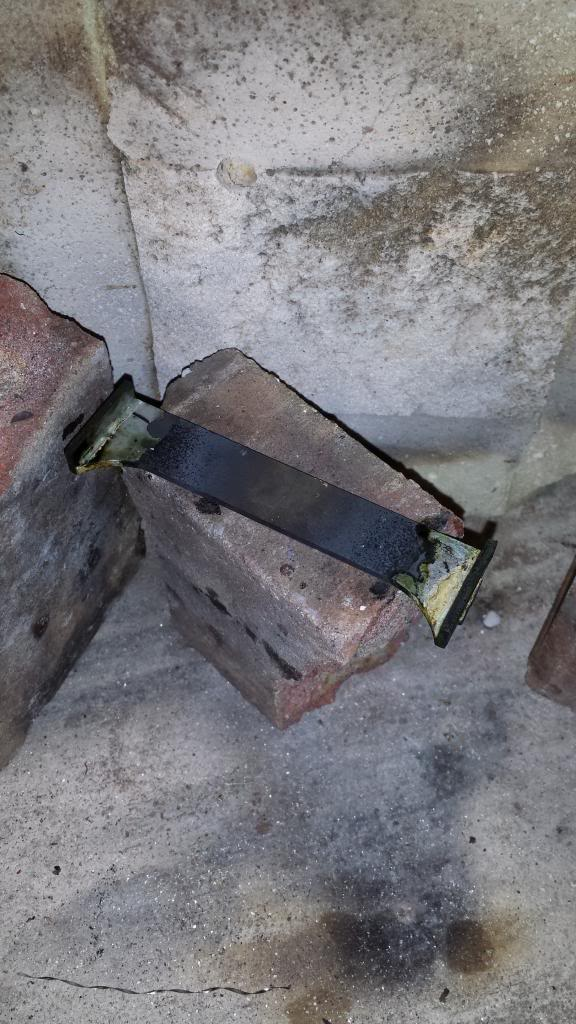
Needless to say Murphy ensured that i ran out of gas just when I needed it most, this picture shows how far I got before the heat ran out, just not enough to finish this corner..lol.. Most of it was silver soldered when this happened so there wasn't too much left to do, the star was then left soaking in citric acid getting a good clean. For the couple of days that I had to wait for the gaz I got on with some simple turning, you'll see what that involved at the end of this entry.
Once the new gas arrived and having silver soldered everything together and given a quick clean I had two other jobs to do. Soldering the beading around the horizontal edges and machining to the correct size of 4 1/8 width. Machining to size was a little problematic,not in so far as the job itself but in as far as being able to hold the job rigid. The mill was ruled out as I didn't have anything suitable for holding the job and no steel angle around to clamp it too so this left me the lathe and it's 4 jaw chuck. Here I got lucky... when placing the stay in the chuck it was obvious that the stay end flange would fit inside the jaw recesses, in fact it was a very nice fit, so this along with the jaws holding tight gave me a very rigid assembly, which when facing off at more than 4 inches from the chuck face helped greatly.
The picture shows how the stay was held in the chuck.. I first clocked the stay to get it as true as possible, faced off and then tackled the other side. With no DRO on the lathe I took off just enough so that all of the face had been machined and then removed it from the chuck and checked the four corners and the centre for size... this showed a max discrepancy of 8 thou between all four corners. I noted all of the measurements, marked the stay accordingly, placed it back in the chuck, clocked it so that I had the corners sticking out by the amount they were over size to each other, held my breath and machined to size....and it worked.. finished width of 4.125... well one corner lost a thou at 4.124 but that won't effect anything.. centre was spot on at 4.125 too.

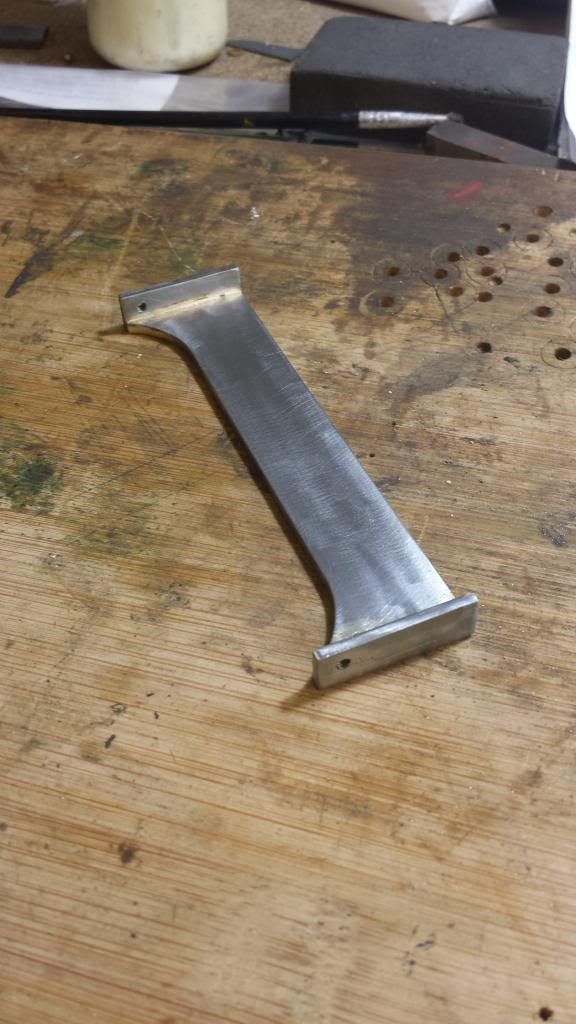
The last job was to solder on the beading, alas I forgot to take a picture for this. I didn't have any suitable material to form the beading and couldn't cut it from sheet as the band saw blade needed replacing, it's ok for small stuff but 3/32 would be asking too much and I didn't fancy cutting it out by hand. I then had an idea... although it is round section I decided to try some soft copper tube that I could form to shape by hand, cut to size, tinned with soft solder, held in place with clips and soldered using a low heat.
I did try flattening the copper first but couldn't get it good enough in the vice so after being soldered to the stay I filed the top and front edges flat, I'll fill the front to finish later when I get to the painting stage. The stay as seen here still needed a little filing and a good clean to finish. Fitting the stay to the frames followed the same procedure as with the others.
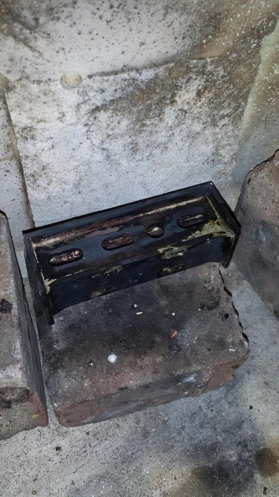
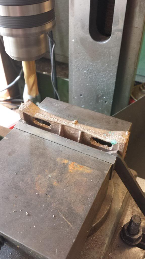
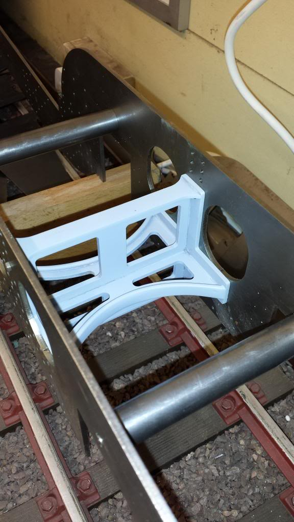
Inside motion stay and for this one a casting was supplier and used.
I took more pictures than usual for this but alas forgot to take some for the more critical operations.. guess I was to busy making sure all was going to plan.
So, the first job was to rough out the stay as the casting was pretty rough... here the bottom is machined flat leaving the centre angled section for later.
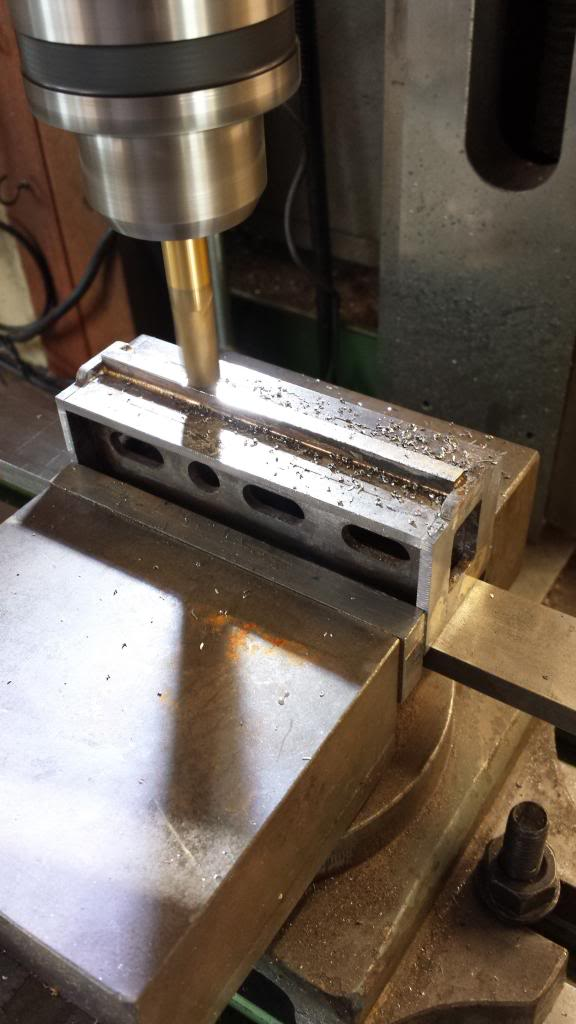
Then flip the casting over and machine first the two ends close to final size which is 1 1/32, followed by machining the centre section flat.
This just left the two wings which were lined up by eye, measured so both were the same and then the centre section was machined flat to join with the wings.
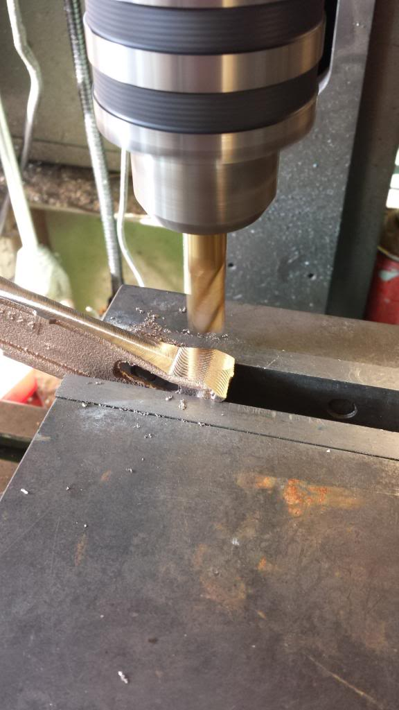
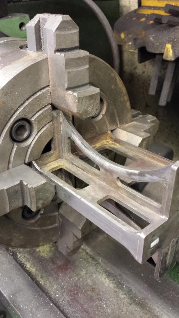
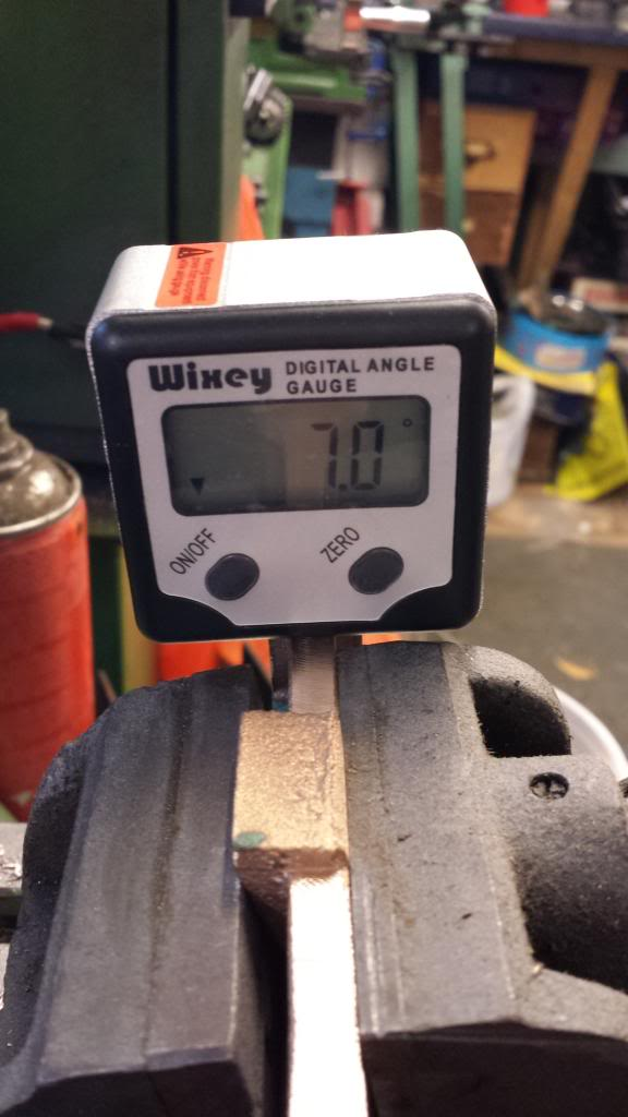
I then machined the two end flanges to size but here I forgot to take a picture so will explain that at the end, but here we see the casting held in the tilting vice to have the centre cylinder slide-bar support machined at it's correct angle of 7 degrees. My new digital angle finder came in handy again for doing this. I also used the gauge to check the other axis to ensure all was square before machining as even though the casting was chocked up with a piece of steel to keep it square I wanted to be extra careful here as this part is very important.
NB: this slide-bar support was left thicker than required and filed down later when fitting the slide-bar to get the best fit/angle possible.
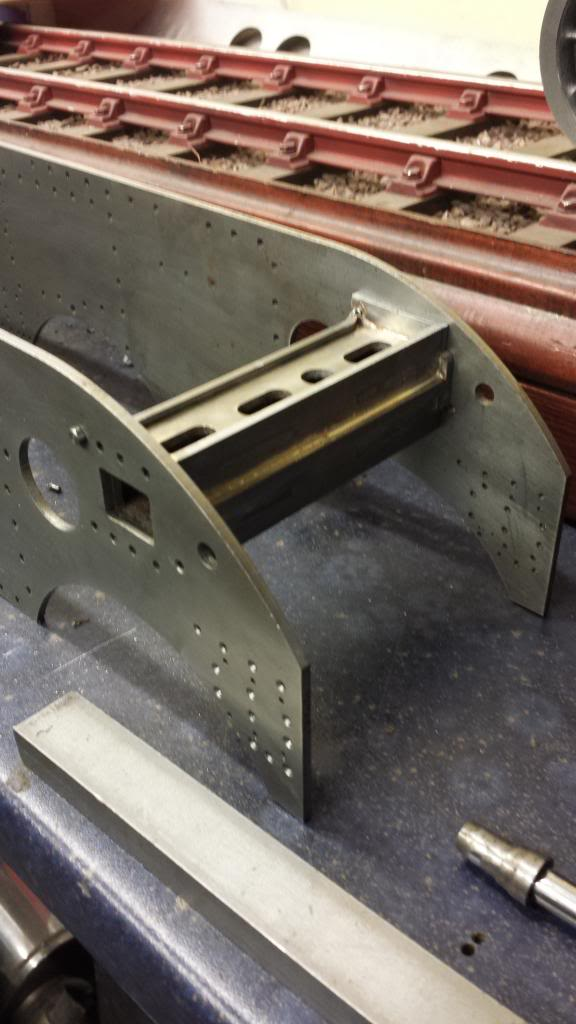
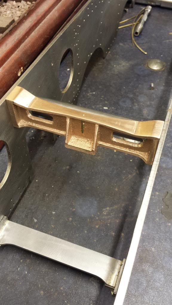
This picture shows the motion stay in place... now I can explain the machining of the width which wasn't a straight forward 4 1/8...note the punch marks.. these are for the centre of the slide-bar support not the stay itself. As we look at the picture the distance from the punch mark to the frame is 2" and therefore the distance to the left is 2 1/8. This is why I forgot to take the picture, I was a little preoccupied. The reason for this is that the middle cylinder is 'offset' and why Don calls it the 'middle' cylinder and not the 'centre' cylinder in his words and music.
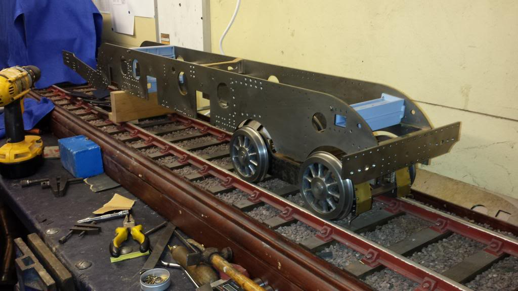
And now to the chassis itself and how far we are getting with the parts required before erection of the frames. Long way to go yet but it's a start.
And just for fun, well I did say that I've made a habit of playing around... here we have the frames to date, sitting roughly in place...well it just had to be done..
Now onto what i did to fill my time while awaiting delivery of some propane,
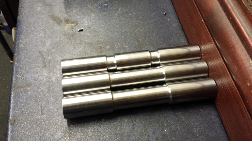
I decided to make a start on the axles.. I took this slowly but did manage in an afternoon to machine from 7/8 EN8 the 3 main axles to a length of 5.812 and centre drilled each end.
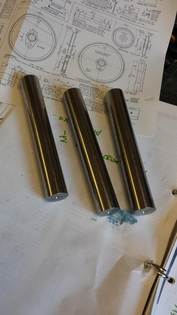
Here's the finished axles, it will be some years before I was back to key them for the quartering, something that on a Gresley pacific with it's inclined middle cylinder isn't a simple case of 120,120,120 degree split. I'll explain this in much more detail when I quarter the wheels later. Some details for the axles,the journals are 1 25/32 long and the recess diameter's are 3/4, the main crank axle has two smaller recesses which are 13/32 before the axle returns back to 7/8 for where the webs will be attached. The webs will also be cut from a sheet of EN8, again this is much later.