The main frames are were we begin properly on the engine itself and I have to say that Don's drawings are more or less a true scale miniature of the original prototype, they are an art-form in their own right. This is the first part, like the bogie I suspect that covering the main frames to their erection will take a number of entries, so i best get on and write them up.
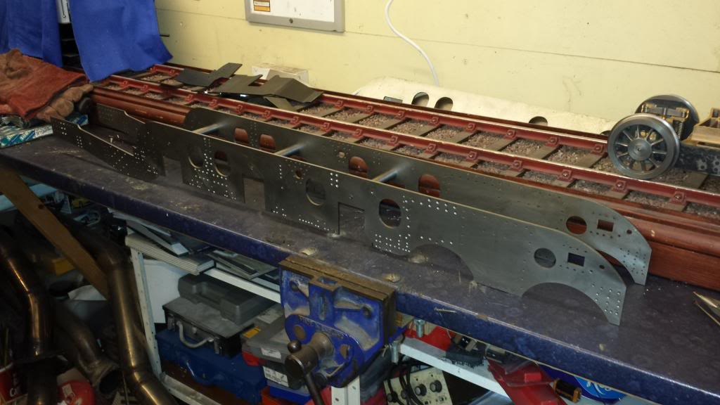
So onto the frames, as you can see in the picture below I went the laser cut route. The main frames ( all 44 3/4" of them) are from Reeves2000, the bogie, doubler plates and trailing frames are all from Steve Harris of Laserframes.co.uk who I am most grateful to him for changing the trailing frames for some of my own drawing.
I'll explain the reason why they needed changing later in this entry.

After taking a close look at the laser cut frames that I got from Malcolm at Model Engineers Laser, there were a few discrepancies but nothing that could not be worked around. So to help future builders of this locomotive here is what I found, first is the horn stay slots, the rear slots are in the wrong place being to far back from the axle slots and thus need re-cutting. Next is the weigh-shaft hole through the frames, the drawing has this as 5/16 but the actual hole that has been cut is 1/2, now knowing that Malcolm usually produces laser cut parts to order and then adds them to his list I suspect this was a request from the original builder.
This modification IMHO is a good one that I'm more than happy to use, it seems to me that the idea was to continue the weigh-shaft bearing within the expansion link bracket into the frames themselves as the bearing there is 1/2, this will give better support to the shaft ( not relying just on the mounting bolts) and also act as a location guide for the bracket, or if that's not the original plan it was now my plan.
One last thing was the profile below the ash pan area, this is a little shallower on the curve going up to the bottom of the frames, I don't know why this has been changed but again it's not going to effect the build itself and won't be noticeable on the finished loco.
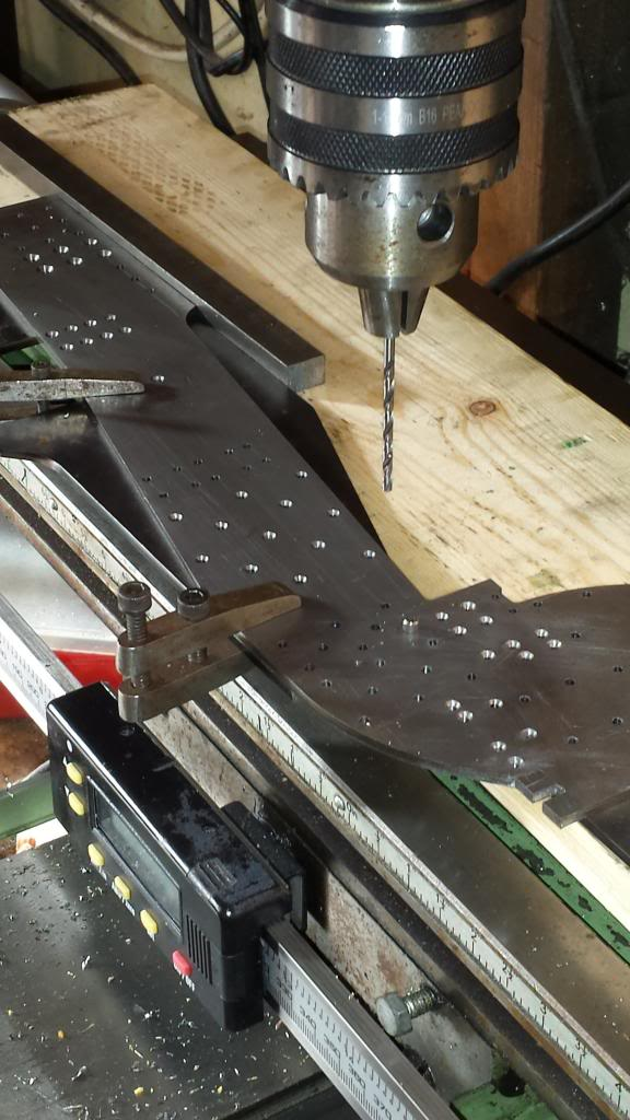
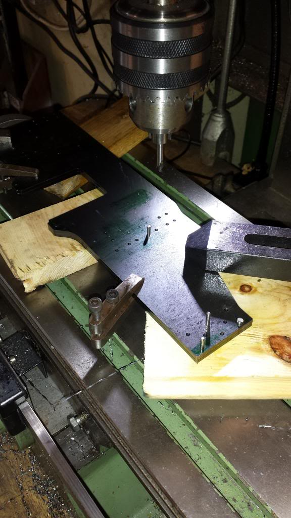
Ok, so having explained all of that a couple of pictures, first to show the frames sitting on the mill bed, these frames are massive at 45" long so I cut a piece of good quality timber to a suitable length to support the frames and to a width so that I am able to clamp the frames to the bed either side without any obstructions. The picture below shows the frames ready for drilling a number of holes to rivet them together, I first checked the drawings to find areas where I could place these without interfering with any locations that needed drilling later. Note the locating dowel at the front to help with alignment. Due to the fact that the frames are sitting on timber I used a level for each hole drilled to be sure that the frames were sitting square, just me being extra careful. The backs of these holes were countersunk so the frames will sit flat for the next operation, that being a few hundred holes...:)
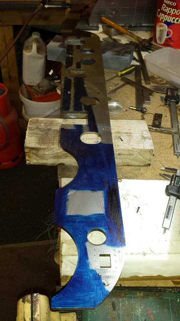
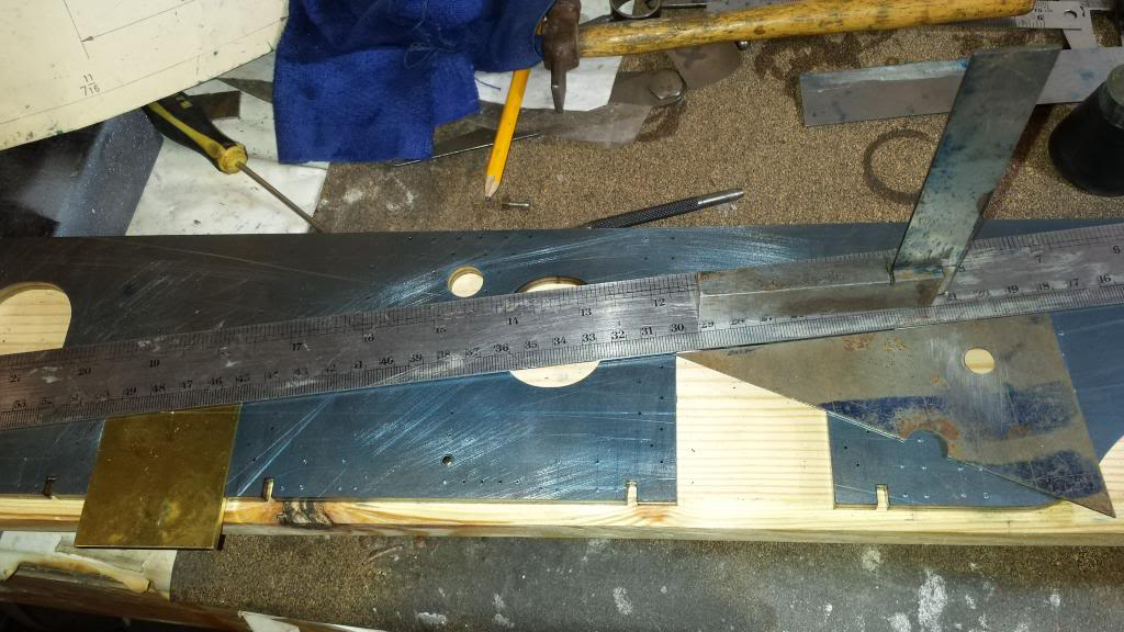
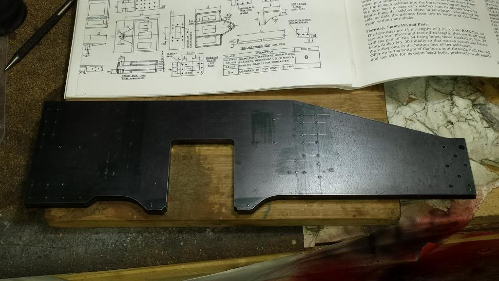
Having riveted the frames together I then applied a coat of engineers blue to the areas that needed marking out ready for the next session. I'll explain the two lines seen in the picture, the parallel line is for the datum line from which all other measurements are taken from and the angled line is where I need to plot the angle for the cylinders which in this case have a 7 degree incline. Now Don states to treat all holes as critical but this incline will be treated extra carefully to ensure the angle is spot on.
After a couple of days head scratching looking a various drawings to collate all of the info needed to plot the various holes in the frames, although all of the holes seem to be marked on the drawings they do not all have measurements so it was a matter of cross referencing with drawings of the various parts that bolt to the frames to get all of the info needed.
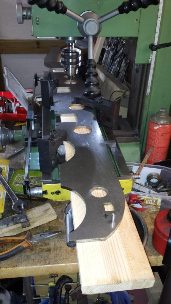
The bolts that run parallel with the frame were tackled first with a few diagonal positions thrown in around the stiffener plates, once they were done it was time to tackle the 7 degree incline for the middle cylinder, something that I took great care over to ensure was right. Picture here for reference shows some of what was involved around the cylinder locations, this was far less daunting than I had imagined which is normal for me once I spend a little time digesting what's going on, classic case of 'it looks worse than it actually is'..
Anyway Don's drawing helped greatly here by giving a number of reference points that help align things correctly, such as the crank centre line. Two points giving a reference point down from the top of the frames and another back from one of the stays , where these cross is where the incline from the centre axle needs to cross. Added to this is the 7 degrees angle stated and the fact that this is a 1 in 8 incline. Armed with all of this info I had many reference points to double check that all was to drawing.
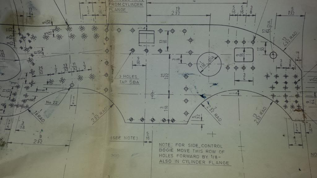
Now, here we see how I drew the angle onto the frames, first job was to machine a piece of brass that fitted tightly into the crank axle slot, the brass had a centre line ascribed and once fitted into the axle slot had the datum/centre line drawn across it and then centre punched to give me the exact centre position for the axle. I then ascribed a line to cross with the two previously mentioned reference points from the frame top and back from the stay. I then checked that the 1 in 8 was correct which it was, spot on at 336 mm distance by 42 mm up, as a last check I did a visual with all other plotted holes near by to see if anything looked out of place.. all was good.
Now that I was happy with the incline I needed to plot the cylinder holes, Don had provided a reference point 90 degrees down from the centre line for marking out the cylinder bolt holes. There were one or two holes that had no measurements but I could measure this off the drawing after first checking other known measurements to ensure the drawing was to scale, it was very very close and I allowed accordingly.
After a marathon 5 days of hard slog, plotting, piloting, drilling, countersinking and also reaming for a few and I think you can see why it took me so long to get the frames ready for service. There's an awful lot of holes and let's just say I'm sure glad that that stage is over with, well not quite as I have some tapping left to do and the horn holes but the frames are close to being ready for erecting.
NB: as the build progressed I discovered a lot more holes needed to be added, not for the frame erection itself but for the many small parts that needed bolting to them.

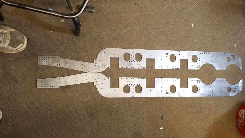
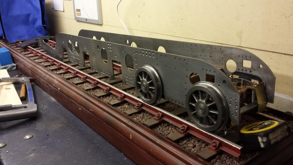
This picture was just me playing to see how the frames looked when sitting on the front bogie, there will be a number of 'playing' sessions during this build..:)
In summary of this first stage on the frames it can be seen that I have cut the new slots in their correct positions ready to be filled with some 1/8 th steel which I was advised not to silver solder in place due to possible heat distortion and so theye were bonded using Loctite and then filed to finish making them invisible when done. I had only drilled/reamed the one central 1/8 th hole for the top of each horn as a locater, the rest I'll transfer across from the horns themselves once machined .
Before I can do the horns and fit them I needed to tackle the trailing frames and stiffeners. I couldn't fit any of these until I'd fitted the horns and done the final machining to size of the slots which I'll tackle with the frames fitted together, so it was a bit of a juggling act for the next few operations.
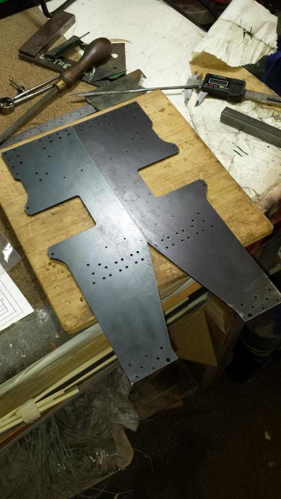
The trailing frames are one of those things that required a little care to ensure they are fitted correctly to the frames so I tackled this part first. This was simple enough once I got my head around what was what..the holes from the leading edge of the frame are 1/8 th back so first I ascribed a centre line for these and then lined up the trailing frames under the main frame with the ascribed line central to the holes in the main frame that they related too. The rear of the trailing frame sticks out further due to the allowance for bending to shape and the fact that the end plates sit outside of the trailing frame but inside the main frames. It's not easy to describe but will become clear when the frames are erected. What was clear though and helped greatly in getting the trailing frame lined up correctly is the rear upper face of both frames are at equal height presumably for the cab floor to sit on and that the lower sections also lined up.
The picture shows how I aligned the two parts and then clamped together with tool maker clamps, the No.22 hole has already been drilled and a short length of 0.156 steel put in as a locating dowel, an extra measure taken was to put a piece of steel along the top edge as a visual aid to ensure nothing had moved while I drilled the 7 remaining No.41 holes that made up the fixing points for the trailing frames being attached to the main frames. Not shown here but before I continued drilling I placed wooden packing under the frames.
Last job before drilling was to plot and mark the various positions for the next round of drilling, as with the main frames I have left the horn holes except for the lowest hole for location purposes.
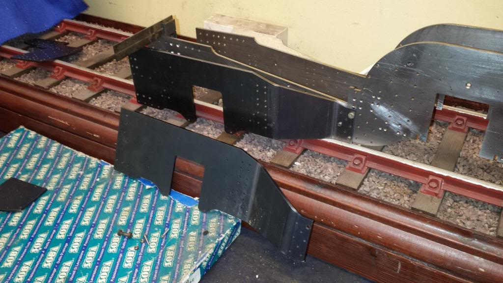
NB: since we are looking at this side on view I'll try to explain why I had to reject these frames as originally supplied. the issue was that yes they had been lengthed slightly to allo for the dog legged type bend but the problem was that the extra material had been added after the bend. IE, as we look at the frames here, the extra metal had been added to the part to the left of the slot, the bend is to the right of the slot and so I drew up a new profile which Steve re cut free of charge, i thank him for his quick response and turnaround. After bending and aligning with the frames these were then a perfect fit. If i hadn't have changed this the trailing wheels would have been 1/4" too far forward.
More good progress with the drilling in this next picture, another hundred or so holes drilled and still on the first drill fbit or each size although No's 34 and 41 have been re-sharpened many times now.
Following the same procedure as before I clamped the two trailing frames together and drilled the No.22 hole first, followed with the 0.156 dowel pushed in to hold things true, once I had done the same to a few of the other holes I was confident that nothing would move and drilled the rest to drawing.
After an hour or two the trailing frames were finished except for the horn holes as mentioned before. IIRC sizes of drill used were No's 22,34,41,44 and 51 , all piloted first with a centre drill.
Here we see I has also drilled all the holes in the stiffener plates, I played safe and first clamped one stiffener plate in it's correct place on a main frame and drilled all of the holes, No's 22,41 and 44. I then cleaned this up and accurately clamped the two stiffeners together and repeated the process for the second plate. I did it this way to reduce the risk of a drill deflecting going through two pieces of 1/8 th steel. Once done I split the plates and lined the second one up with the other main frame to check all was good, happy to report all holes lined up perfectly... one happy bunny...
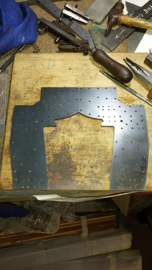
One thing to point out the stiffener plates had been cut a little low where the boiler throat sits,not by much but enough so one hole for the boiler is effected. Not a problem, I can still bolt this up as per normal, once I get to this stage.. hmm.. probably 5 years or so away.
NB: I don't think that I was far out on this estimate of time..:)
Bending the trailing frames, I had planned on making a couple of jigs that would fit to the frames using the various holes and for the end of the jig to be in line where the fold was needed thus ensuring the folds were in the correct place and more importantly the same for both frames. I then decided this wasn't going to work when folding 1/8 thick steel plate. After carefully marking out I had planned to borrow a press to fold the metal, 1/8th being far to heavy for my home machines to do. I asked my son if I could use his press at his work which he was more than happy for me to do but had a better idea. There's a metal plant next door that has a 25 ton folding press so he arranged for me to pop in there and the owner was most helpful and within a short time I had two perfectly formed trailing frames.
Picture shows one frame temporary held in place to check that all was to plan, the frame fits perfectly, it's at the correct angle, sits square with the main frame in regards to height and it also ends at the correct length so in all a very successful day.
Last picture for Part 1, i turned up 3 spacers at 4 1/8 length to accurately space the frames apart for fitting the stretchers as I began to fabricate and fit them. I hadn't realised until this point that the frames come in at the rear from the 4 1/8 width to 3 1/2" at the drag box, guess I missed that little bit of info. I decided to do all of the stretchers before fitting the horns and the frame stiffener plates, once all parts are finished I'll strip the frames down, fit horns, place back to back and accurately machine the horn inner guides. then rivet on the stiffener plates and erect the frames properly which should be only a few days work...haha, yeh ok...:)