On to the bogie spring set-up, again, lots more work involved here and unlike any of the other suspension components on a Gresley Pacific, these are helical springs rather than the leafs springs on all other axles. There was one exception of the class to this rule, 1470 Great Northern as built had helical springs on the main driver wheel, not on the other two main drivers (Bogie too of course), others were leaf springs as normal.
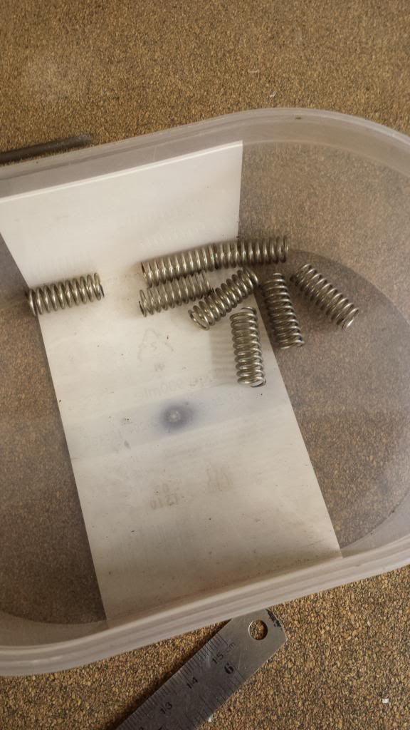
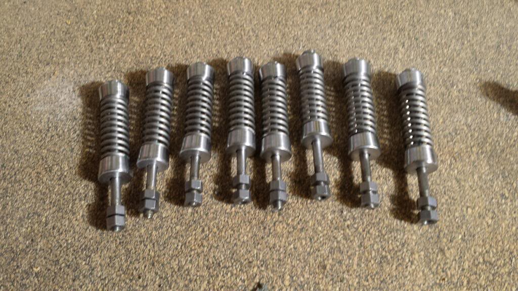
First job was to make the springs, are the 8 springs in total for the bogie suspension, specification is 3/8 OD 18 swg and 1" free length> I bought a length of spring to this spec, the picture shows the finished springs having been cut and ground to length.
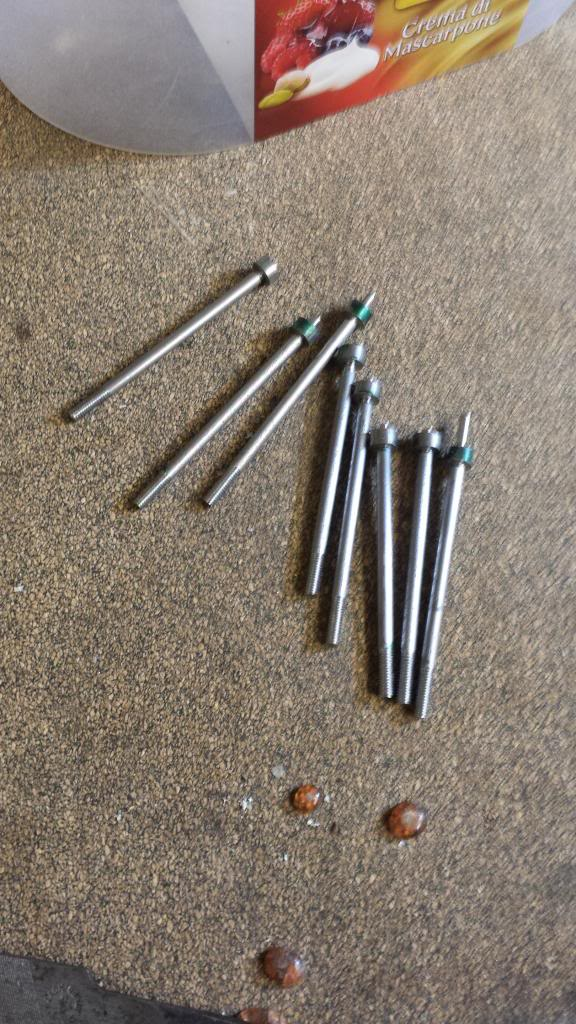
The next job was to make the spring pins, I decided to make these in two parts as done a number of times with similar parts to save time. The first part being the 1/8 shaft that has a 5 BA threaded section .406 long and plain shaft at 1 3/4 long, I machined an extra small spigot to the end of this to locate the top on. The top was again a simple turning job with overall dimensions of 7/32 diameter and 3/32 height plus a central hole to fit the spigot on the shaft, I machined the top to size once it had been silver soldered to the shaft. Picture shows the two parts awaiting silver soldering.
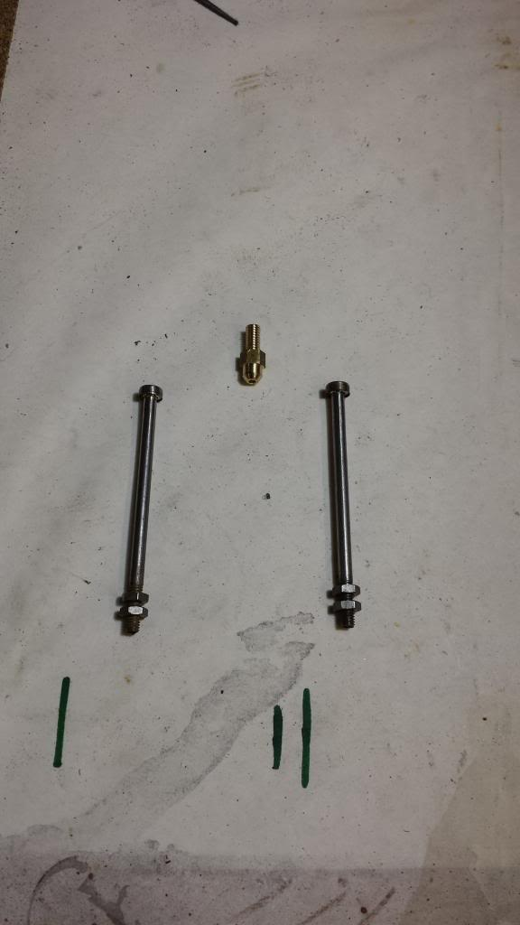
Here we see the finished spring pins and the spring yoke cup, the cup sizes are 7/32 AF hex, a 3/16 ball machined on the bottom to fit the recess on top of the axle box and the threaded section above to fit it to the spring yoke. I have modified the cup a little, first it has a N0.54 hole through it and the threaded section I beefed up ( for strength) to 4 BA instead of 6 BA to allow for the small bore going through it. This is for the oil to pass through, you won't see it for a while, but later I added oil cups to the top of each spring yoke on either wing to directly feed these points
Next was the 16 shock absorbers which didn't take too long as they are a lot easier than those on the tender.
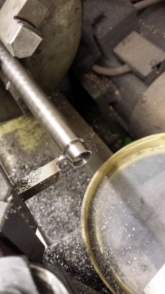
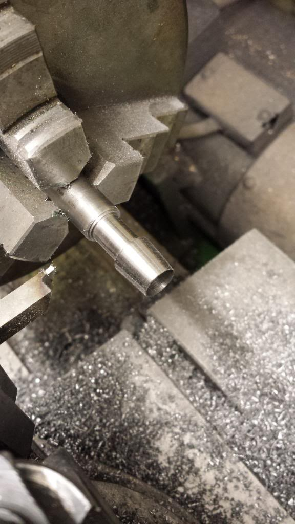
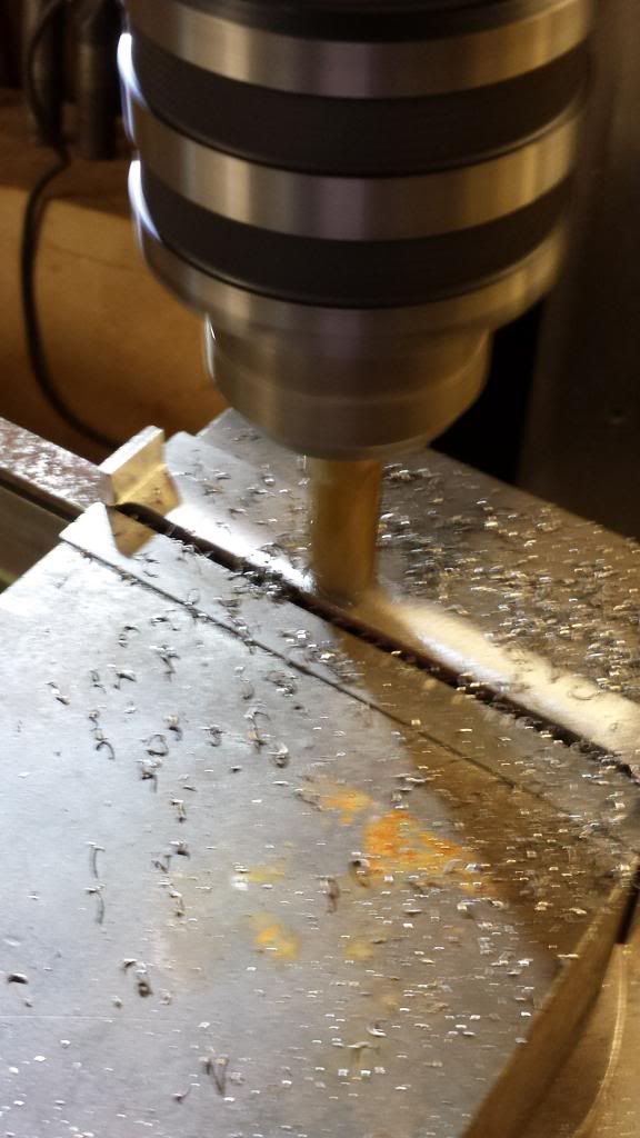
There are 8 spring sets that involve a little repetitive machining but nothing too long winded, the picture shows one of the shock outer casings being parted. The specs are 7/16 diameter by 7/32 height which I have tapered 5 degrees, a 11/32 recess was cut for a rubber disc to sit in and there's a No.29 hole drilled through the centre for the spring pin to pass through.
There is also a small disc (not shown here) that fits into the recess thus sandwiching the rubber to form the shock, I added a small lip to the top of each disc for the spring to sit over.
Once I had finished all of the metal parts I then needed to give some thought to a simple and quick way to cut out the required rubber discs. Using the same bar stock still in the 3 jaw I continued with a No.29 hole to a depth of around 30 mm, next I cut a recess to the same size of 11/32 but deeper, depth wasn't important just needed to be enough so the rubber sheet didn't stop the cutting action. With the top slide still set at 5 degrees I cut a taper but this time continued until I was left with a sharp edge on the face. Once this was parted off I heated the cutting edge tip to cherry red and quenched it in oil to harden.
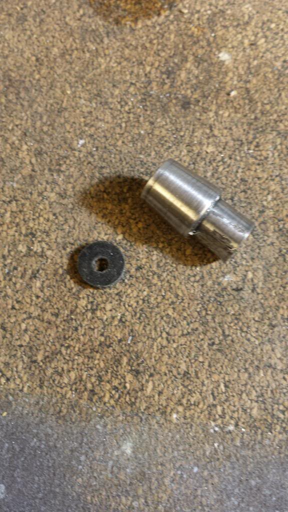
It was then a simple job to place the rubber sheet onto a piece of hardwood, the cutter held square onto the rubber followed by a sharp tap with the hammer and while still held in place to drill through the centre guide through the rubber into the wood with the No.29 using a power drill. To begin with I did this the other way around, drilled the rubber, placed the tool over with a length of 1/8 BMS to line up and then tapped the tool with the hammer but had a tendency for the hole to end up off centre so changed the order of doing things which worked very well. Picture shows a cut rubber disc along with the tool for doing it, note the hardened tip just visible.
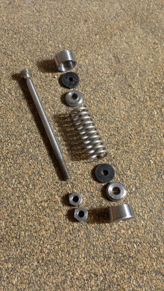
A picture to show the vast amount of parts that make up one spring ready for assembly
And this picture to show the finished spring assemblies ready for fitting to the bogie.
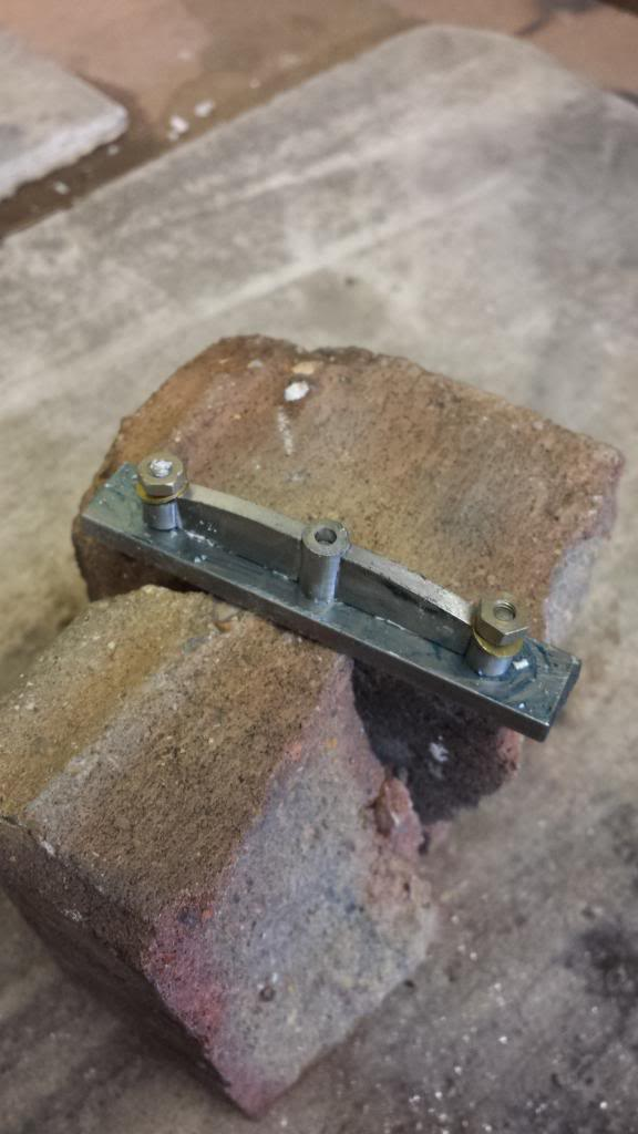
Now follows the bogie spring yoke consisting of 5 parts that needed silver soldering together, 3 columns at 1/4 diameter spaced at 1" intervals. The larger centre column I drilled and tapped 4 BA for the yoke cup to screw into, this was also drilled all the way through so that i can get oil to the keep and it's oil pad through it, the cup and axlebox without too much of a problem. To help with this I later added an oil cup to give me a reservoir for the oil to sit in. The two shorter outer sections were drilled No.30 for the spring pins to go through. Between the columns are two 1/8 webs that are shaped to fit. The ends of the webs were scalloped out using a 1/4" cutter so they fit nicely around the columns but not too tightly so to allow good penetration with the silver solder. I then made a simple jig to hold everything together for soldering which is shown here ready for heating. The jig and the associated 4 BA studding, nuts and washers were coated liberally in soap to stop them getting silver soldered to the job in hand.
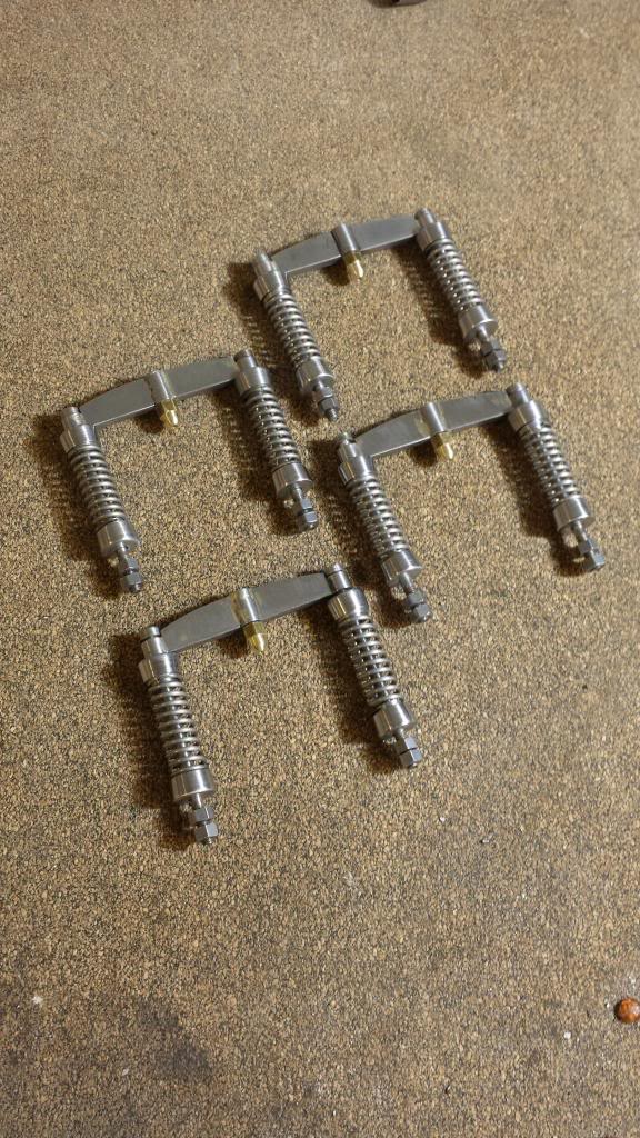
And here's the assembled spring assemblies fitted to their yokes. Now this is how the drawing has them. Plus the added mods to allow oil to be fed to the oil pads, to help visualise this it's the middle of each yoke that will have an oil cup fitted to the top, the oil passes through the yoke into the brass ball, this sits in the top of the axlebox with it's own small recess to hold oil. The oil then travels through the box onto the axle below and around to collect in the oil tray. Hope that makes sense.
Following a request that I put on the LNER forum for prototype details on the spring assemblies, Eddie Giddans (spelling) came forward ( many might know him from the TyneSide SME) with the info that I needed for which I'm most grateful. I had noticed that 4472 today had no upper shocks but I wasn't aware until Eddie pointed it out that these upper shocks were taken off during the change over from the swing link bogie in the early 30's to the side bearing bogie fitted today.
This is an easy fix where I can just remove the upper shocks.
On to the two stays, both made from 1/8 BMS and silver soldered together, the rear stay has a section milled out of the top to give clearance for the two vacuum cylinders that will be positioned close by.
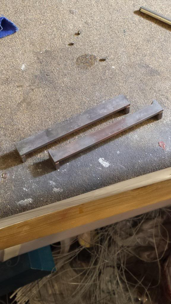
Once they had been tidied up a little they both had their ends machined square until they were exactly 4" across, the picture then shows the rear stay being machined down in thickness to the 2 mm shown on the drawings although I left the ends a little thicker for more strength.
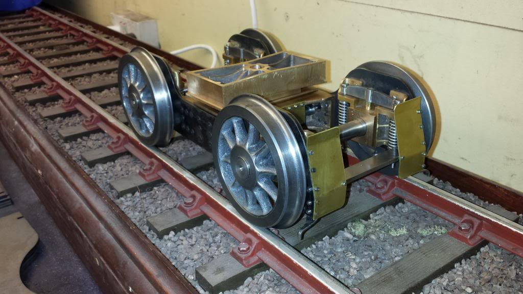
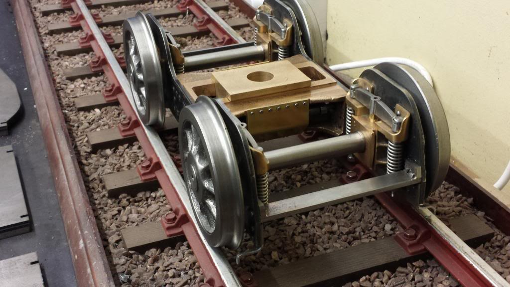
Here we have a near finished bogie, you can see the two stays in the picture plus the guard irons. I later changed the way that the irons are bolted to the frames just to make things more practical.
I haven't set the springs yet in this picture, it's probably best to do this once the loco is close to completion or at least after the boiler is sitting on it's frames.
At this point Eddie kindly pointed out to me that I hadn't finished the bogie as it was missing it's dust shields and so after a couple of hours most of which was spent drilling into the hardened edges of the laser cut frame I had the dust shields fitted. Please excuse the temporary 10 BA bolts of different sized heads, I had none left and dug these out of the used bin to be replaced later. You can also see clearly in this picture that the top shock absorbers have been removed from each spring set. Again, as per prototype, thank's to Eddie's knowledge of all things LNER, his name will probably pop up again later, he recently helped me greatly in researching the correct cross slides for the pistons, those as drawn by Don are a much later design, IIRC 1947