

The Cartazzi (some say Cortazzi) trailing wheel system is one of those things that, for me was a delight to make and also unusual when compared to most other locomotive solutions for the rear trailing wheel.
The principle being that the axleboxes are angled and swing as one in an arc to pivot the rear trailing wheel rather than the more common rear pony truck. They are designed so that the whole axle is 'self centering' utilising wedges that are incorporated on the top of the axleboxes and under the spring plates, they act in unison to each other. A bit difficult to explain in just words but hopefully by the end of the entries covering the making of these things will become clearer to those not familiar with the design. Of course, all of you LNER builders out there will already know about these things.
I'll start with the Cartazzi horns, these are another of those parts where there's an awful lot of machining set ups for the little buggers. One thing to note , just as with the axleboxes, the horns are also angled to match.
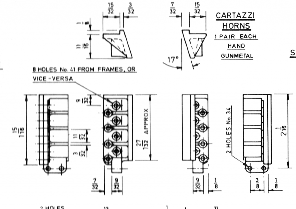
I'll post a picture of the drawing first... it will save me giving dimensions etc.
First picture of the horns themselves is the stage I got to before changing from Don's words which basically just involved running a file over the outside edge of the rivet to frame face to give a datum to start from. As stated previously, I don't really like relying on a hand filed face for this but it was reasonably flat anyway and looked pretty square to the other faces and so on this occasion I followed Don.
So that was the easy part, now things got a lot more involved and I deviated from Don's next set up which involves removing two jaws from a 4 jaw chuck and to hold the casting via the remaining jaws by the two horn stay mounts. From what I've read before, I believe that Don didn't have the use of a mill and perhaps this is why he suggests doing it this way, I do have a mill and was a little concerend about holding the castings with only two jaws so made use of said mill, it didn't really make life any easier but felt better to me.
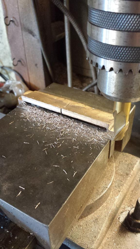
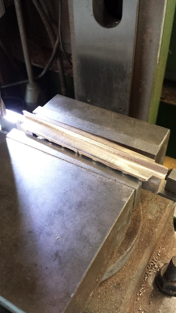
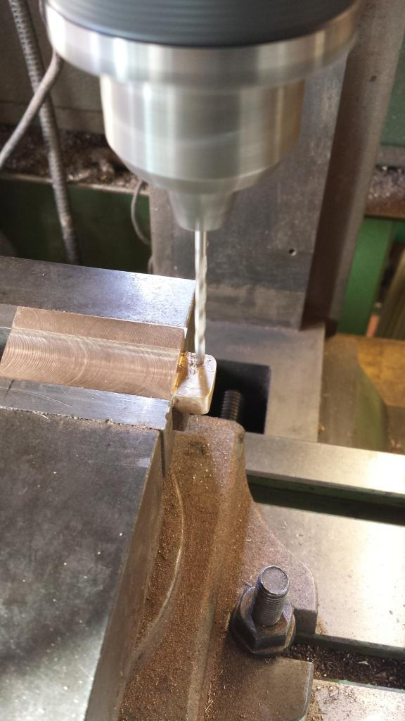
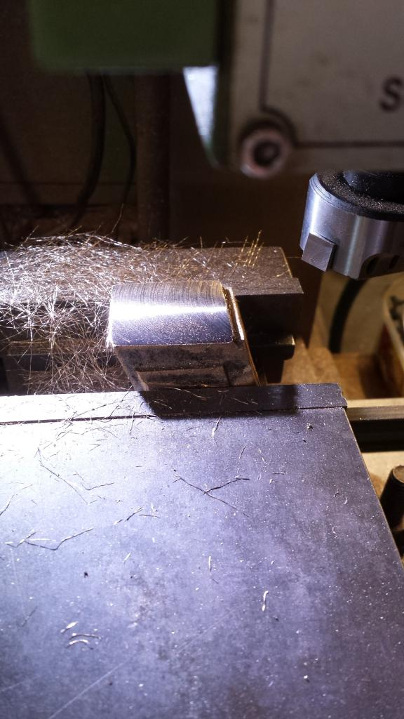
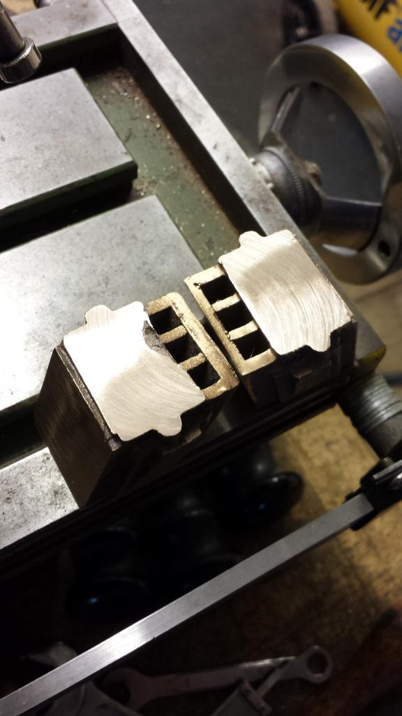
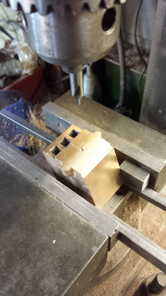
Ok, so with the machine vice checked for squareness to the mill head, ( I tend to do this now and then for piece of mind) I packed up the horn castings from underneath and behind and machined the opposite edge square... or at least i think that's what i did next...it got a little confusing with so many machining set up's...lol Picture shows this edge being faced
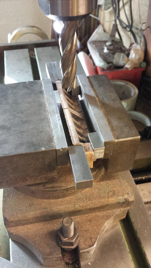
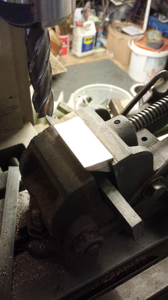
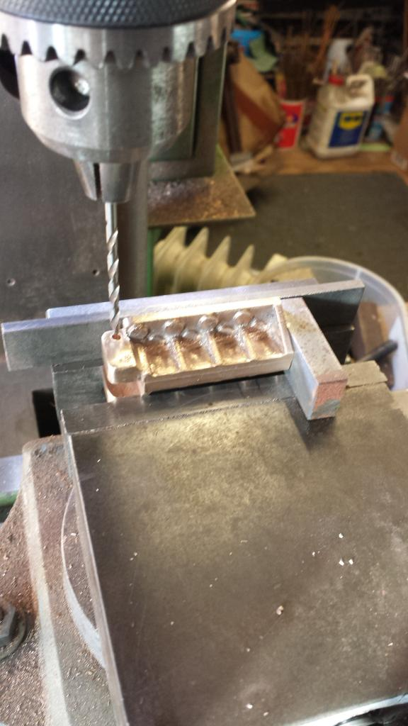
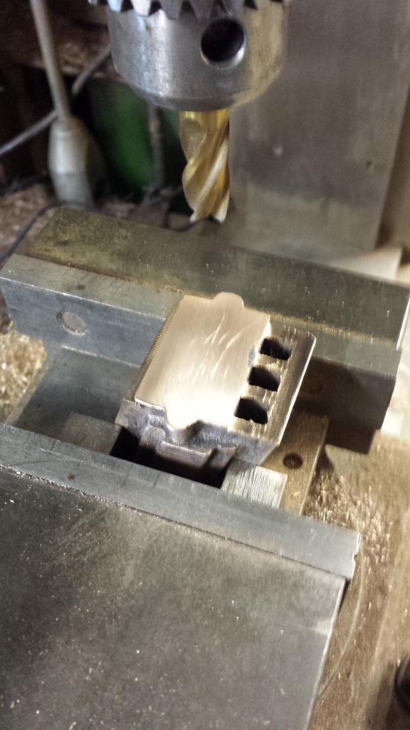
Next was to machine the last of the three edges, as can be seen the casting was packed out either side of the horn stay supports and also had packing underneath, it didn't matter that the horn supports hadn't been machined square yet, the important thing was to have all 3 faces machined so far square to each other.
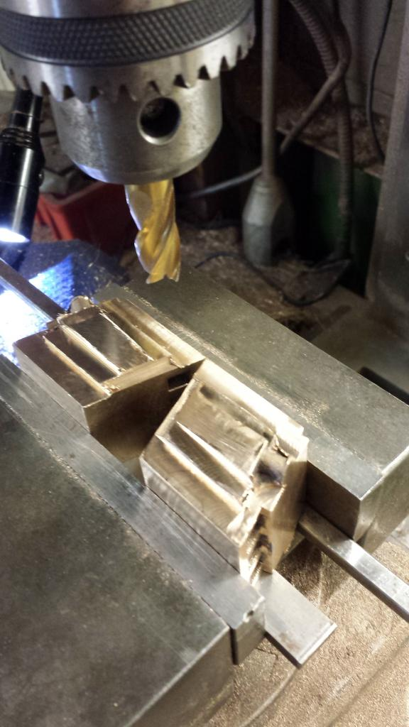
With those three faces done I then moved on to the step to fit the frames, as can be seen on the drawings the back edge of the horn is 13/16 from the front, I did this first and then followed a further 1/8 for the final face depth leaving an overall dimension of 11/16 as shown, both sets of castings were machined to this point.
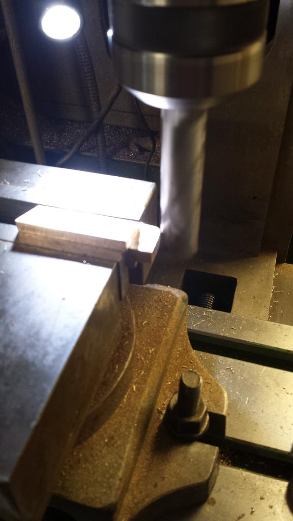
This left the one main face to machine, that being the 17 degree running face for the axle box, the castings were cut into singles and in turn set up in the tilting vice set to the required angle, I left these slightly oversize until the axle boxes were done, then fit them to the trailing frames and true up in situ.
It was then back to the machine vice to finish all the other parts as per drawing... far too many set ups to list them all in sequence but basically the horn support tabs needed machining to size, horns needed machining top/bottom to size and everything checked.
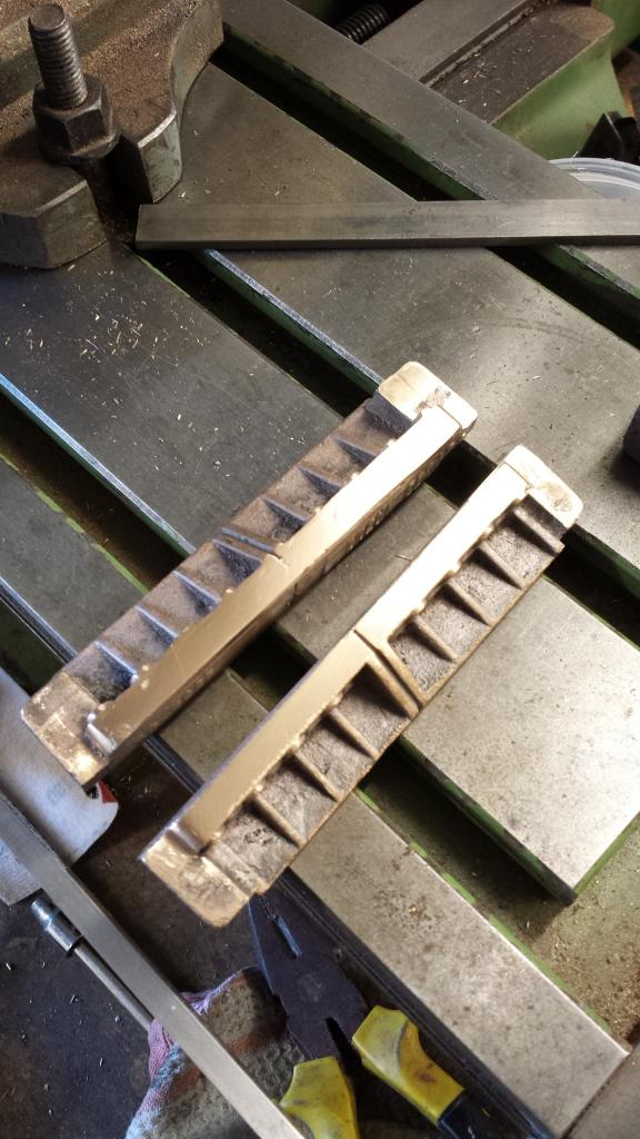
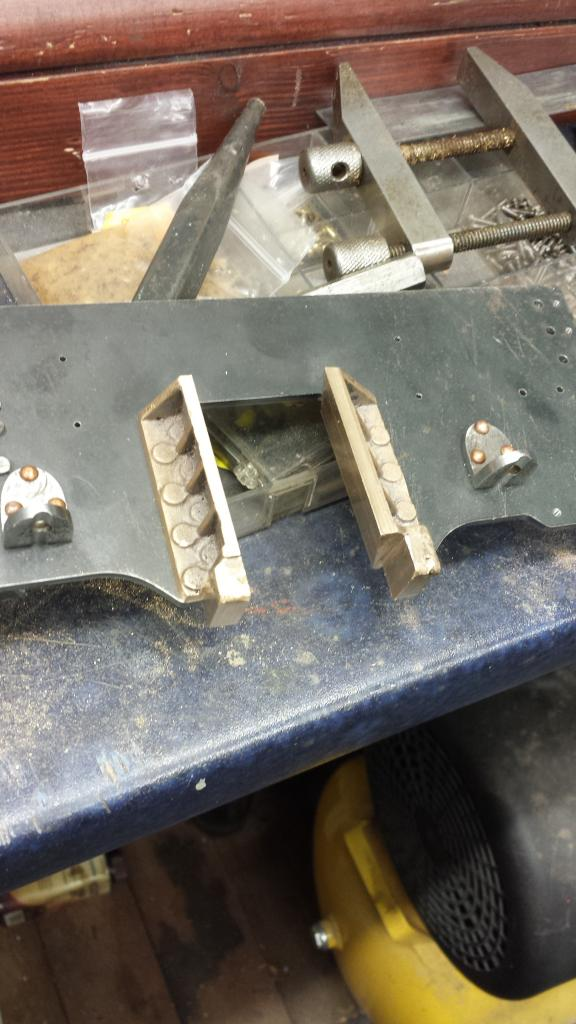
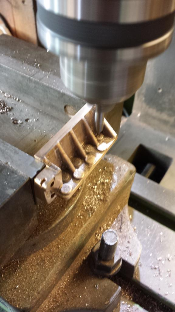
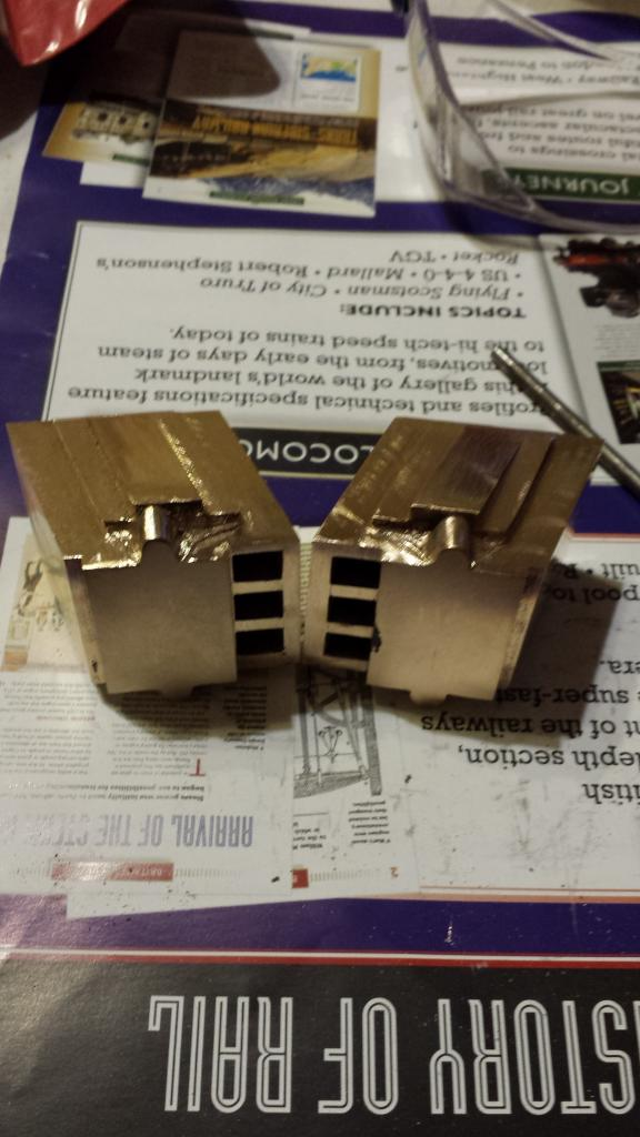
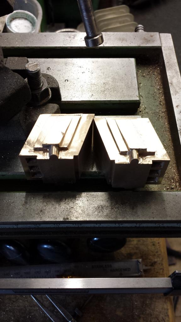
Final picture for tonight shows the horns, not completed but finished in as far as roughing out is concerned...the hornstay tabs need a lot of work still, holes drilling and back face machined to size and rounded off, picture shows the horns sitting on their associated trailing frame...I also have to drill the rivet mounting holes and here i'm going to be very busy... if you look at the nearest horn you can just see that the inner raised mounting points are half covered by metal...not a good state of affairs to say the least, i suspect i have a good few hours grinding ahead of me and fun...I think not...riveting said points too...oh the joy...
On to some drilling, first I drilled the two holes in two opposing horns for the hornstay bolts to fit into, as seen on the drawing.
I then held the other horn of the matched pair for the one side and placed the horn already drilled on top, aligning it by placing steel blocks to the side and back. this was just to get the hole in it's correct position height wise, it's depth is determined as with the first by being held by it's machined step in the machine vice, all holes were center drilled first...hope that all makes sense guys...sorry for out of focus image
I then drilled all of the mounting holes except for those that are on the leading horn closest to the horn cheek , it's not possible to drill these from above due to the angle of the horn. Also the two lowest holes that I had already pre-drilled on the frames themselves as a guide for height of the horns which probably wasn't a good idea as when drilling through they are out a little from the boss, however in my defence, so it seems are many on the prototype..
I then aligned one horn up with it's frame, clamped in position (ensuring it was held tight against the frame opening via the machined step) and drilled through from behind from the two holes mentioned, riveted in place and then did the same with the other horn, checking height by a depth gauge and with a suitable drill bit placed through two of the horn stay bolt holes. Once happy with the horn positions I drilled another hole in each, this time from the front and riveted in place.
It was then back to the machine vice and this time the holes closest to the leading horn cheek were marked out and drilled from the back, one was very good the other a little off but as mentioned, so are they on the prototype. With these holes drilled it was a simple task to turn the frame over and drill all remaining holes through the pre-drilled holes in the horns.
Last few jobs were to mount the horns with their proper bolts, give a coat of acid 8 and fitting of the trailing frames to the main frames. Regarding fitting of the 7 BA bolts, I first fitted 2 on each horn, chiseled off the backs of the rivets temporary holding the horn in it's correct position, removed them and then fit the remaining bolts as per prototype. You can see here what i meant when saying the lowest hole is off centre to it's boss, if i'd bought the horn down a little more I think the boss would have been below the frame.I still needed to file these to shape and decided it would look worse in having half a boss. once painted it all becomes irrelevant anyway but still a little annoying at the time, but as pointed out, the prototypes that I've seen of Gresley pacific's vary in this, some being out more than my model and so i'm happy...There's no real measurement that I can see given for the height of the horns to the frames so i went by photo's and also by the curve of the boss which happens to match that of the frame.
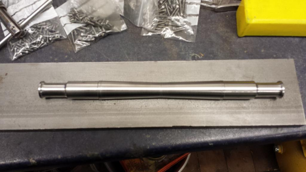
having done that lot I decided that I needed a break from the mill and did a little turning instead, some light relief shall we say. This lead to the trailing the trailing axle, it's very similar to the tender axles although slightly longer at 8 5/16 whereas the tender axle's were 7 5/8. Journal's and wheel seats remain the same at 1/2 and 5/8 respectively, also centre taper goes to the same central diameter of 1/2. Something that is different was the distance between wheel seats, 4 5/16 for the trailing axle and 4 7/16 for the tender, this meant the 2 degree taper had to be increased slightly to get a match in the centre of the axle.
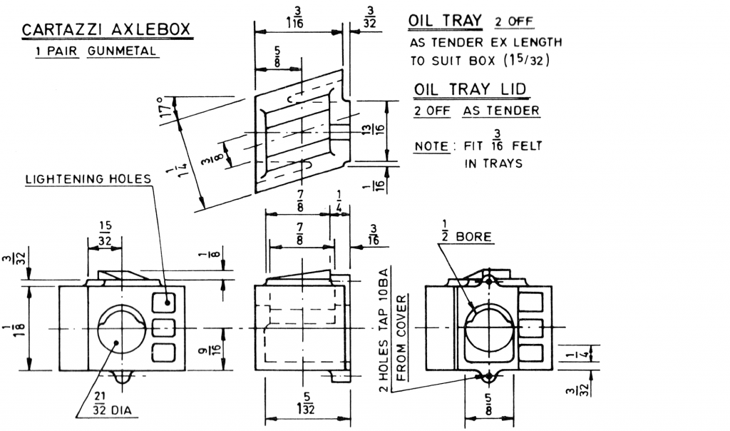
Cartazzi axle boxes, bless their little cotton socks...these required a number of set ups so this next section may be a little long. I mostly followed Don's methods while doing my own cross checks to keep an eye on things. The castings looked pretty good although I did discover a blow hole which needed addressing, more on that later.
Ok so first off a picture of the drawing that I'm working too, it looks fairly involved to begin with , it is, but like most things becomes clear once a start is made.
Having first checked the angle of the box working faces with the horns I filed flat what one could call the trailing face and then held the box in the machine vice and machined the leading edge face flat and to size.
Both boxes were machined until the middle of the oil tray cover spigots lined up with the height gauge set at 15/32 as per drawing.
With a datum now set for ensuring that the axle is bored in it's correct location width wise I then machined the opposite face until the axlebox was a good fit in between it's horns, an important check here is that the back of the axlebox ( not yet machined) is parallel to the chassis centre-line, this is critical or the axle bores will not run square to each other when later set up in the machine vice for drilling. The way that i have approached this is to first get the axleboxes sitting snugly within their horns and their back face square to the chassis , it's highly unlikely that once the axle is in place that it will be running square as the trailing frames are two separate entities with angled horns that could not be joined back to back for machining, my thinking is that clearance needs to be allowed for for the axle to operate properly and by setting up like so i should have plenty of lee way to adjust any problems if they arise, to most obvious method being to radius the horn faces. I'll look at this stage once the axle is sitting squarely when it should be a straight forward job to do..i hope...

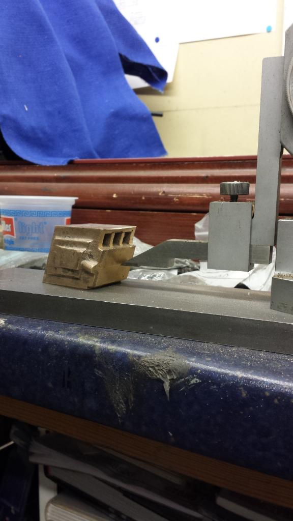
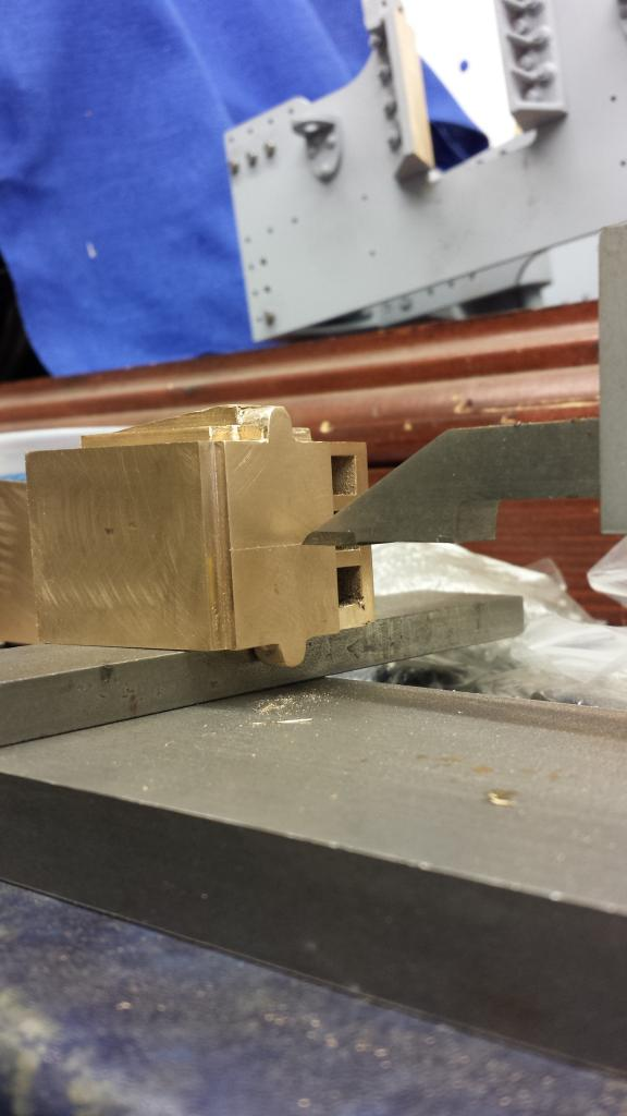
Picture shows an axlebox held in it's horns higher than normal to check the back face is square to the chassis as stated.
With both axle boxes to this stage a check was made to see how things are looking with axle alignment ( note that the boxes are sticking out further than they will be when finished, this is due to first, the need to hold the axle in place on the outside of the boxes and inside of the oil cover spigots and second due to the fact that the boxes haven't been machined to size on that axis yet)...I have to say it looks very good, as long as the bore drilling goes to plan all should be well. Also of note here is the newly added 'T' section stay below the trailing frame spacers...believe it or not there is yet another stay that goes roughly below where the axle is sitting, you can just see the holes already drilled in the main frames ready for the stay.
We now move on to the serious side of machining these axleboxes, the picture shows a start has been made on machining the axle boxes to their correct depth, front was machined flat as shown here and then the back was machined down to final size. Note that one casting has a flaw showing where the oil cover will sit, this was what I referred to earlier with a blowhole in one of the castings. This was filled with JB Weld and machined as per normal once cured.
A little more progress achieved here on the shaping of the cartazzi boxes, there was a lot of final finishing involved on these things. The boxes having now been machined for depth, I then used the top spigot as a reference point to get the correct spacing between front and back facings, the spigot needing to be 1/4" out from the front face of the taper wedge to give the front facing size and then 1 9/32 back from this face to give the correct depth for the axle box machined using a fly cutter, note to self must get a a nice face-mill cutter (NB I have one now). Next was to cut back 3/32 from the front face to get the overall depth for the axle box of 1 3/16 using an endmill, during the same setup I machined the oil tray outer section to size.
Picture shows this stage, note I did need that filler of JB weld although only just, most of the flaw having been machined away, just visible to the right hand side of the oil cover face.
Now the height of the box needs to be machined to size ( 1 1/8) , Don states that the excess material should really be taken from the top, (i guess a mix up with the pattern) but this would involve removing the cast wedge control portion and brazing a new section on, as Don says it's just not worth it and to remove the metal from the bottom. I looked at the casting, took a few measurements and decided that I would remove most of the material from the top , especially as these surfaces are a sliding mechanism and thus better to be machined to have the best chance of working properly.
Using packing to clear the lower spigots I held both axle boxes in the machine vice to ensure they are both the same size, I was surprised that I only needed to take a couple of thous of the top to keep the wedge at it's 1/8 height clear of the step below, pleasantly surprised though...
Last job for that day was to file off all burr and clean up the spigots/wedges a little, I finished these once the oil tray covers had been made, using said covers as a jig to get both spigots the same.
Following on from the last days work I cleaned up the spigots a little more using a 2mm cutter...smallest that i had at the time. The spigots are still about 20 thou oversize which as I said will be taken care of once the covers are finished. Mind you these parts won't actually be visible, the prototype's seem to have a dust shield that hangs down from the wedge control plate that sits above, looks like they are made out of some sort of material, perhaps rubber, I'll see what I can find suitable. There's also a metal dust shield that's bolted to the leading horn, I plan to add this detail later too.
NB: I worked out later that the dust shield that can be seen on some of today's Gresley pacific's must be an added item, perhaps only during preservation? Not sure when these were added but what I do know is that I haven't seen any sign of these shields in photos from the 30's. I did later fit the mounting plate but left of the covers.
On to the 1/2" axle bores, first job was to mark out both axis using the height gauge again, thought being that this should make both axleboxes the same not wanting to set up in the 4 jaw with all the angles involved, in hindsight perhaps this wasn't the best way to do this as when both were done they were out a little when placed back to back. when i say slight I mean very slight, I wasn't worried about this as the cartazzi needs some slack to work properly anyway but it's still a little annoying> Height wise both were spot on, just fore and aft being out a little, i'm guessing that the cast angles although looked good when compared to the horns must have been very slightly different, when finished this didn't show up as a problem so all good.
Then did a little old school using an optical punch to spot the centre's...there is an axlebox under there somewhere...honest...
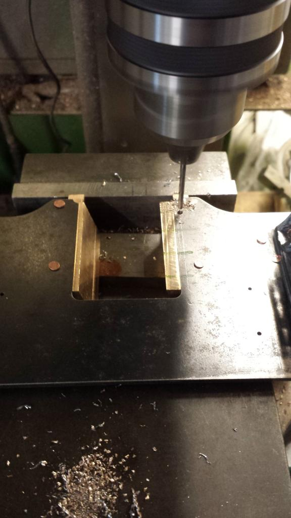
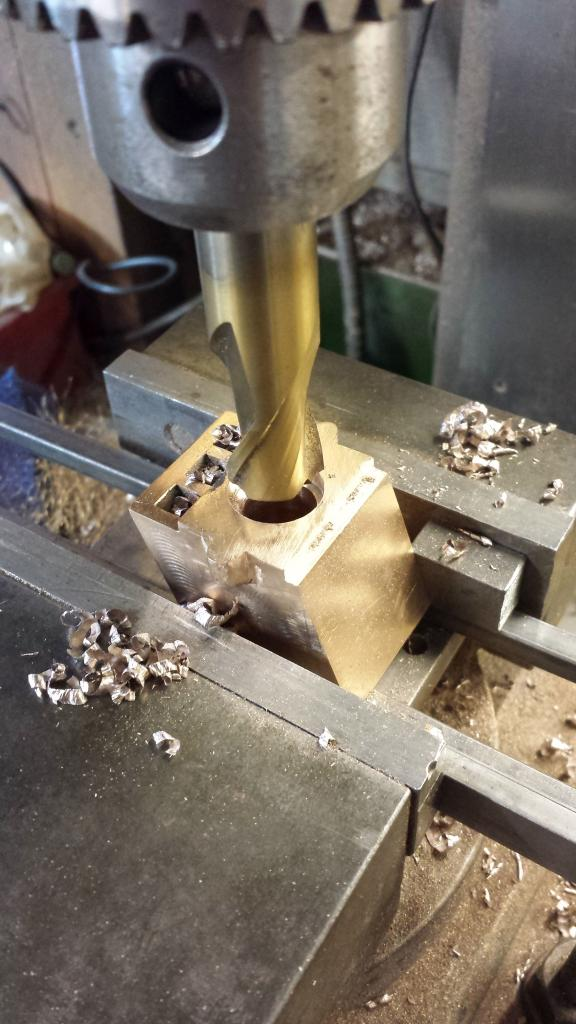
With each box in turn back in the machine vice i drilled the 1/2" hole, first off using a centre drill.
followed up by this lot, bore finished to size with the reamer
Once the 1/2" bore had been reamed to size it was time to open up either end of the journal for the axle to fit in, this involved using a D bit ( I managed to find the same bit as used for the tender boxes) doing the front first and them the back.
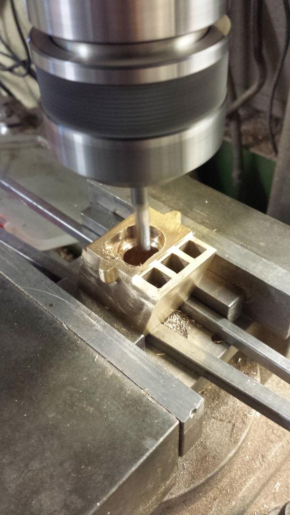
I seemed to have missed a picture here, forgot to take one while machining the oil tray recess, anyway here's one of the axleboxes with it's oil tray recess machined using a 6 mm long series cutter. For those not familiar with this design the axles have to be pushed in at an angle and then lock in place when they are parallel with the journal. Once the oil tray is in place everything is locked down so to speak. I still have the other axlebox to finish the machining of it's oil tray recess, hope to get that done tomorrow.
two pictures for tonight...first the picture that i forgot to take yesterday when doing the oil tray recess in the first box, here's box two showing the first stages of machining ...iirc the total depth of this recess is 1.156, which took a good few hours, luckily there's only 3 faces to machine.
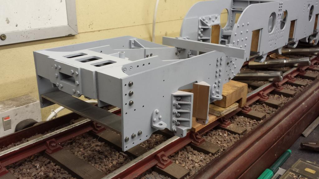
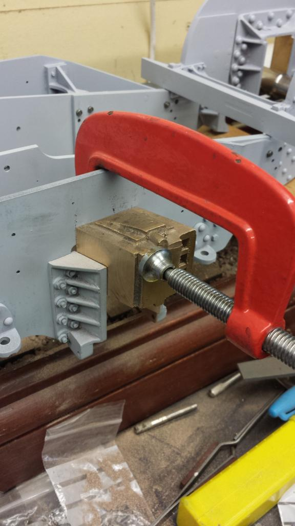
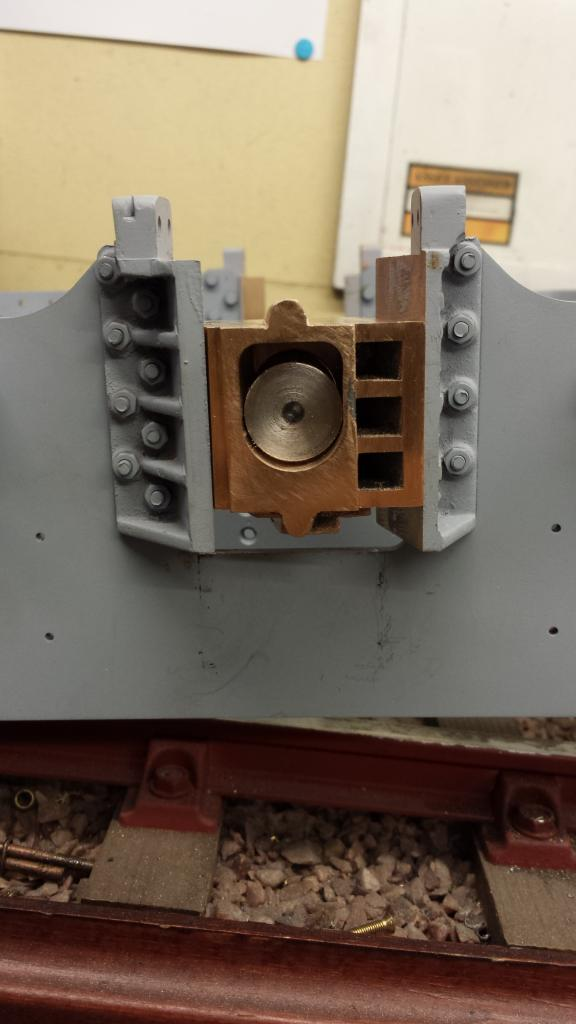
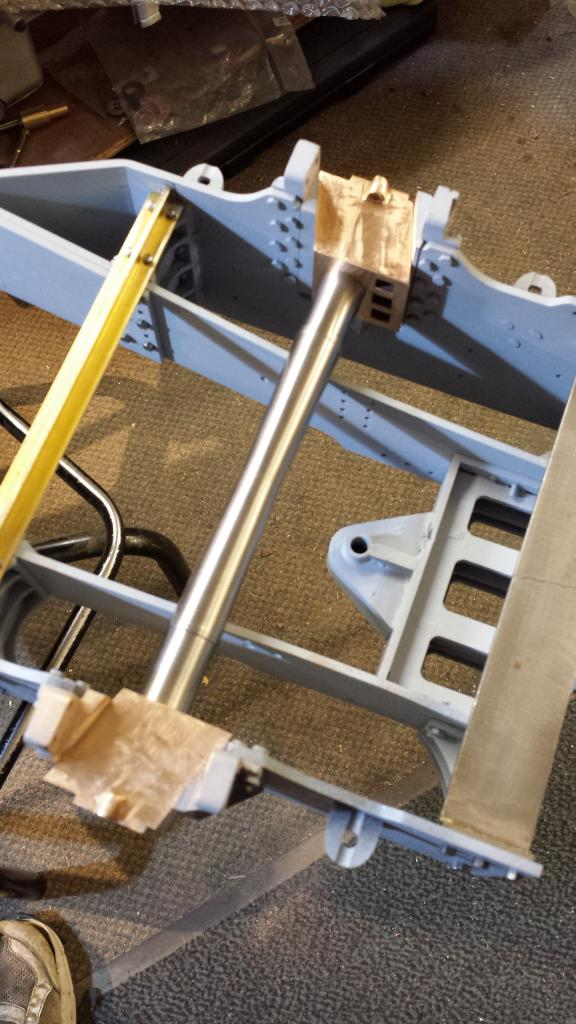
and now we see the trailing axle assembly sitting in situ, I've put a couple of blocks under ( actually on top as we are looking upside down) at roughly running height. I was surprised to find that there is sideways movement with very little fettering. I needed to remove a little more from the horns nearest camera which has around 3/16 movement to the left as viewed...the other side is clear and will slide about 3/4 inch out, in fact it will slide out altogether. I believe the reason for it being tight on the left is due to the miss position of the bore on that side putting the axle a tiny bit further forward. It sits squarely as seen in the picture when in mid position but may need a little fettering to allow more movement if needed. I won't do any more to this until the main drivers have been fitted and I've tested the chassis on the club track, I suspected it would be fine as was, however it would be an easy fix if it needed more movement...all in all I'm pleased with that especially after messing up the bore on one box, it's one of those jobs that you don't really know the state of play until the main parts are assembled.
NB: now that the chassis has been tested on the track I can confirm that this cartazzi axle works very well requiring little extra work. What I did find beneficial was to file a slight arc on the horn face to encourage the axle to move freely in it's supposed arc movement. but leaving the center of the horn face as to drawing, thus no play as such. It now has more than enough movement to negotiate the usually tighter bends as experienced in miniature compared to those in full size.
Cartazzi hornstays
The drawing has these as steel, I have cheated with suitably sized telescopic brass tube doubled up (two tubes telescopic) for both extra strength and to bring it up to the size needed and also 1/4 x 1/16 brass bar for the ends. I believe these are more than adequate for the job being held between very substantial horns. First picture to show the various parts before being silver soldered together.
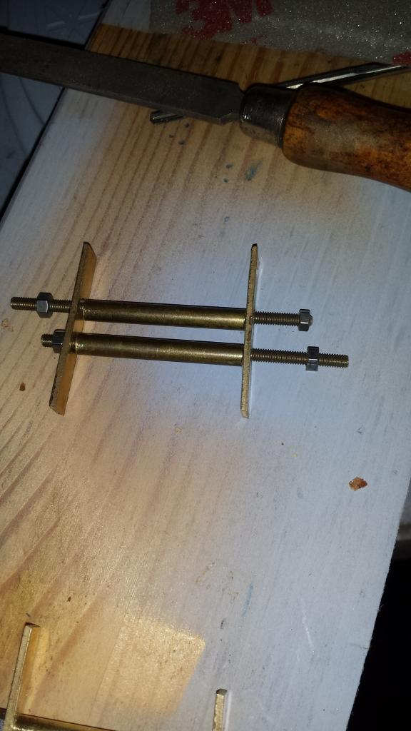
Next, one of the stays before being silver soldered, I used 6 BA brass studding to hold the parts tightly together, I chamfered the ends of the tubes to get a good joint between the tubes and the end plates, the studding was covered in soap to ensure that no solder adhered them to the tubes or end plates. After cleaning the end plates were cut to size and profiled by hand using a file.
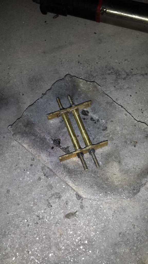
close up showing the underside of the hornstay..
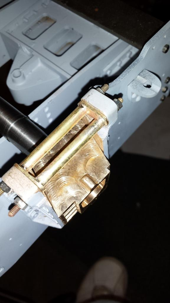
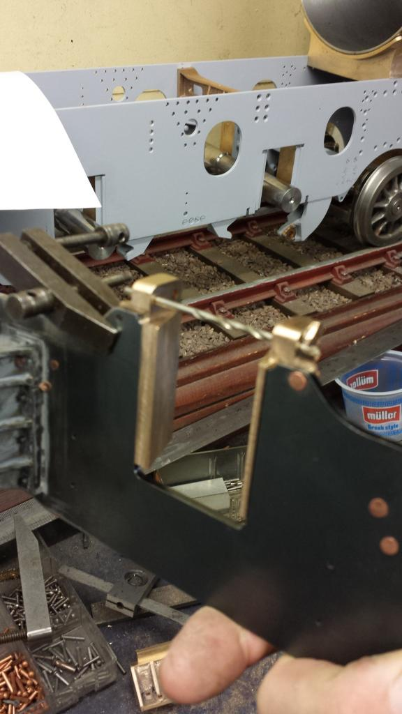
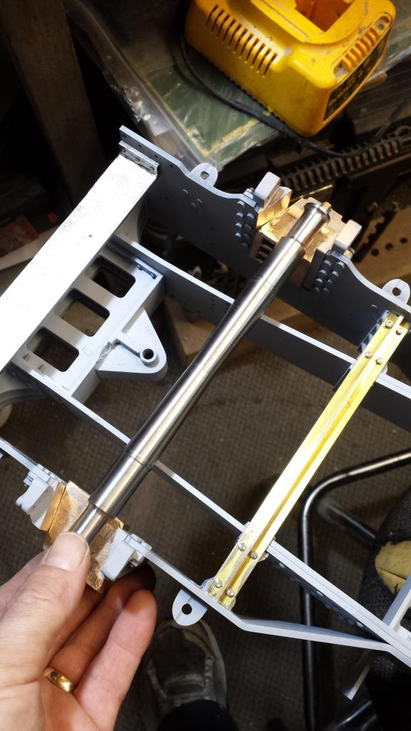
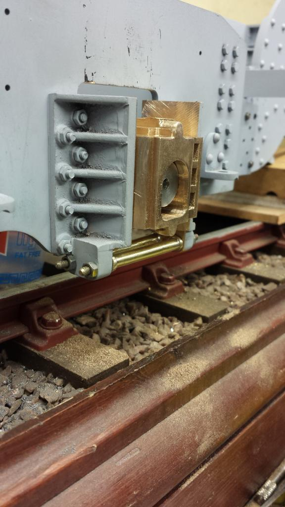
and finally a close up the right way up, a lot of cleaning up still to do as evident in the photos. The hornstays are nearly there, the axle has been propped up close to it's running position, still lots to do in this area but it's getting there, I next needed to make some proper stay bolts up from some 3/16 AF hex steel bar.
Hornstay bolts
Simple turning really but care needed to be taken due to the length and size....First thing I did was to make up a cutting tool from some 1/4 sq tool steel.. I needed something suitable for doing all operations using just the one tool and that would also clear the live centre required to keep the stock parallel.
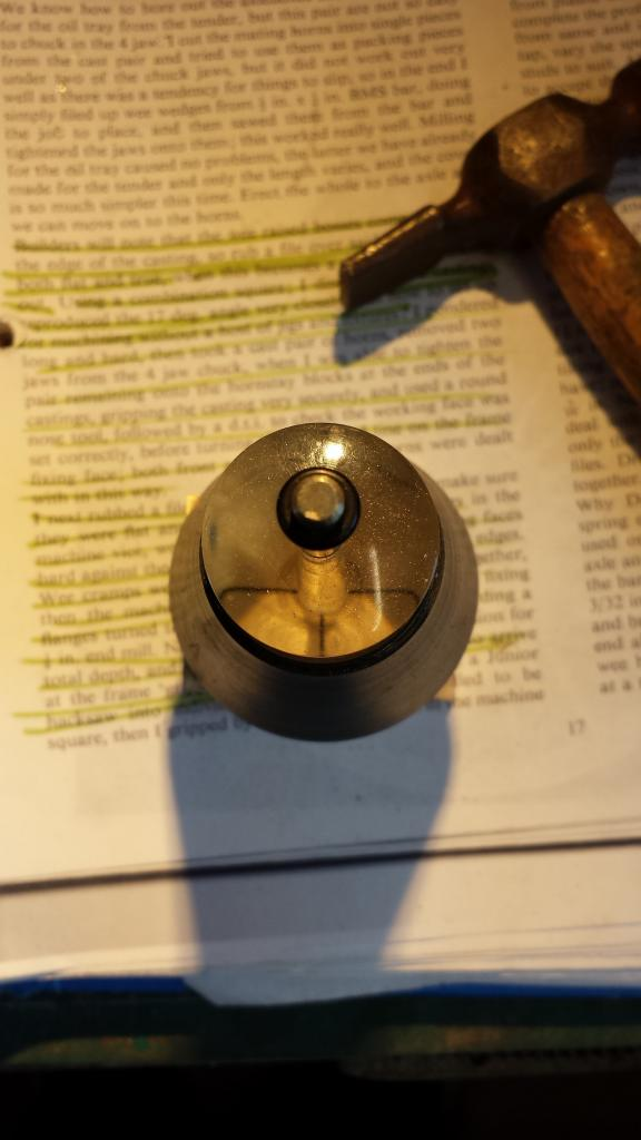
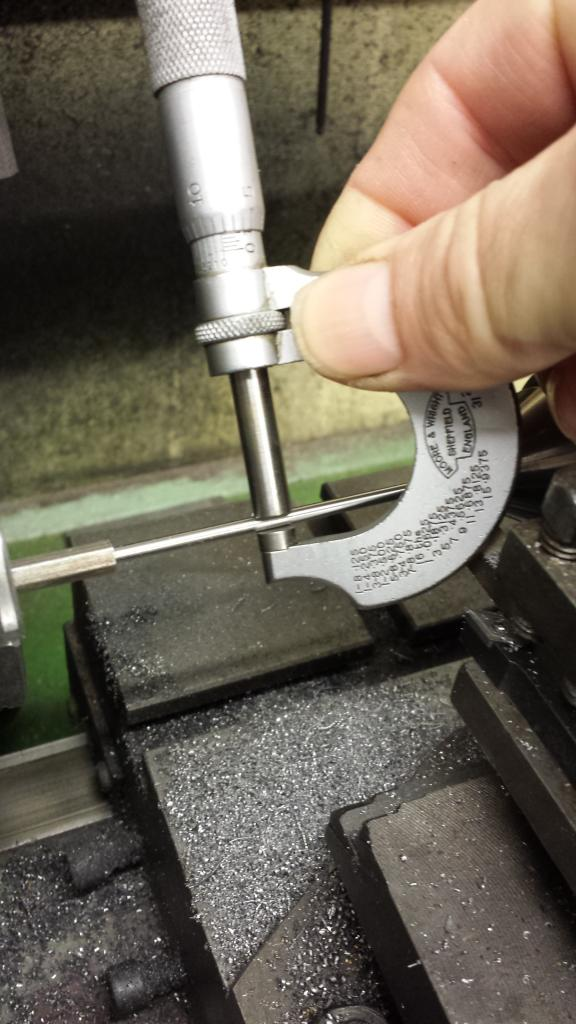
The bolts start off with some 3/16 hex bar which is turned down for the 6 BA thread required on it's end and also to fit the No.34 holes in the horns. Each bolt consists of a 2 5/32 plain shank to fit between the horns, 1/4 threaded section and a small spigot on the end, the hex head is 3/32 wide. Picture shows the first bolt after all turning had been completed except parting off which BTW is also done by the made tool. Once to size and checked the Mic was locked for ensuring the other 3 bolts would be the same, live centre removed and the tailstock die holder used for the thread, then followed by the final job, parting off.
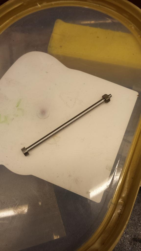
Here's the first bolt finished...now it should have been a simple job to do the next three...it would have been if I had had enough 3/16 hex stock....alas I only had enough for 3 bolts....not to be defeated i searched around and found an old allen key with the correct sized hex, after some heat treatment to temper it below hard steel it was a simple job to turn up as per the others....good job I never throw those odd Allen key's away....
Finally the bolts are fitted to the horns, I have fitted them with the threads towards the rear, prototype pictures show them in both orientations so I've followed good mechanics practice....always fit threads to the rear to avoid dirt buildup, I'm sure the same should apply for a locomotive, I stand to be corrected of course.......
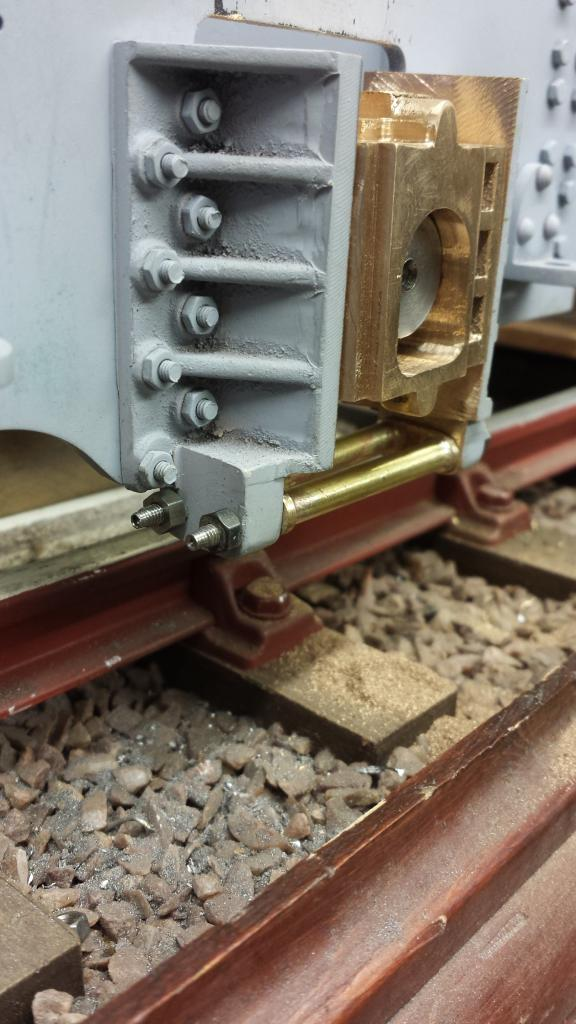
looking at these close ups it was obvious that I needed to tidy up some areas before painting....this I duly did much later and the end result looked pretty good if i say so myself...:)