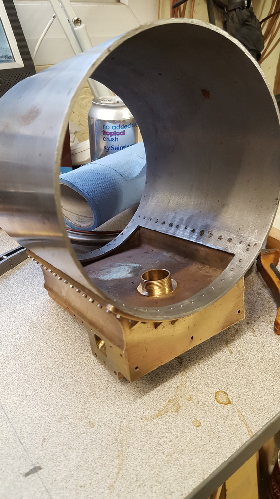
Continuing with the smokebox, I cut out the access in the smokebox tube and started work on the standpipe for the outside cylinder's exhaust. In the first picture, I have clamped the tube to the saddle ready for spotting through the 8 BA mounting holes. Firstly I filed down the saddle flange a little to match the drawings at 1/8 thick and then spotted and drilled the 4 corner bolt holes ready for tapping 8 BA, I can't remember if Don taps these or uses nuts on the inside but I decided it best to tap them all irrespective.
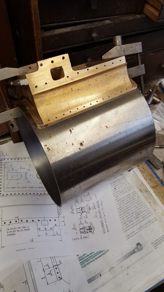
Having done that I refitted the tube with the 4 bolts and marked out the area that I needed to remove, picture shows the 4 larger holes that I drilled for the corners and also you can see some of the spotted holes ready for drilling/tapping. I have also ascribed out the area that needs removing but you can't see it here.
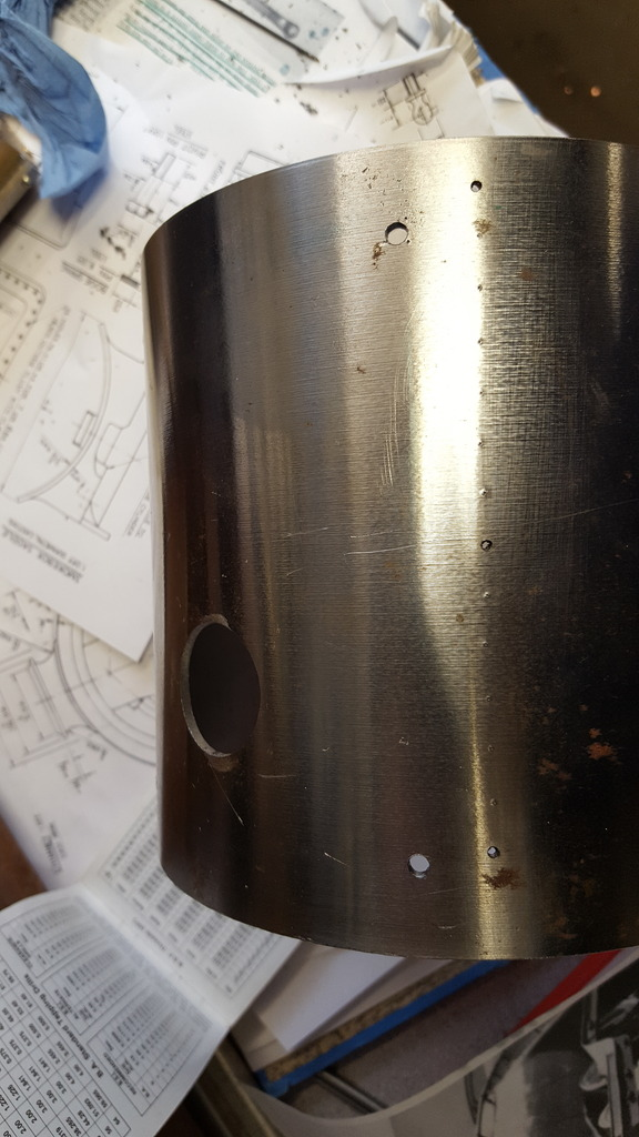
Here we have the section removed...I then refitted the tube and dealt with the other 8 BA mounting holes, drilled and tapped all 56 of them. This was tough work as the steel that the tube is made from is very tough, think it may be some form of stainless as it's bright and has little signs of corrosion, all that I do know is it started life as a 7" steel tube with 1/2" wall thickness.
NB: I later changed the 56 mounting bolts choosing to have some of them as dummies, I'll explain the reasons later when we get to that part.
Moving back to the saddle, before I started machining again I needed to deal with the small wedges that fit around the front flange, here they are cut ready to fit.
Now, originally i fixed these on with Loctite, I did a test piece first and couldn't break it off with my hand, and I think it very unlikely that these little things will get anywhere near the 250c required to break the bond down so should be fine. However, later I thought twice on this and soldered them on as Don recommended. Note the chimney and petticoat castings in the background, they'll be next on the list...
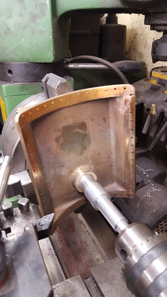
Back to the mill and I set up the saddle square to the bed and level to it too, set 'Y' at zero with the centre of the saddle and then after finding the front edge moved along 'X' by 1.750 as seen here.
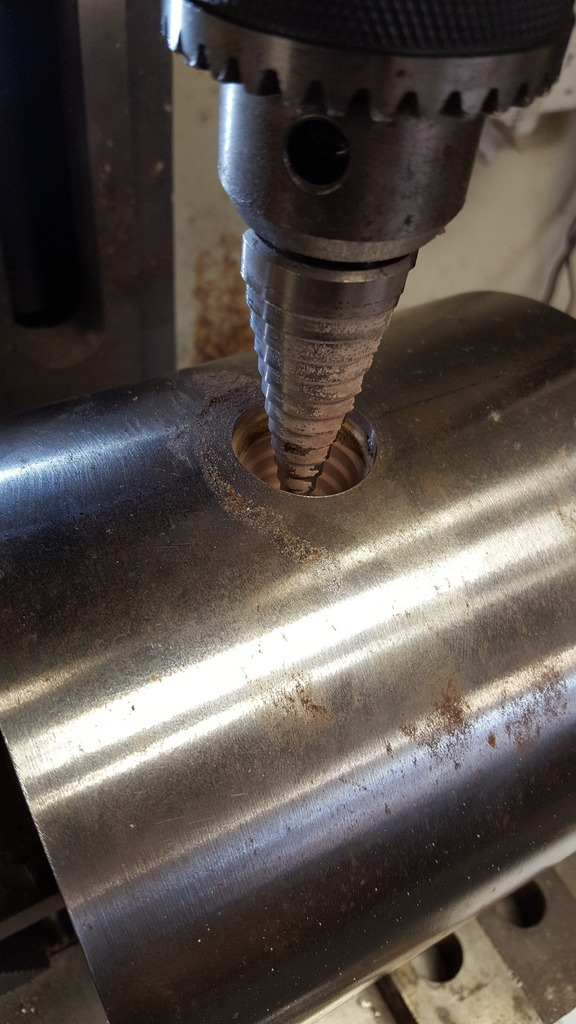
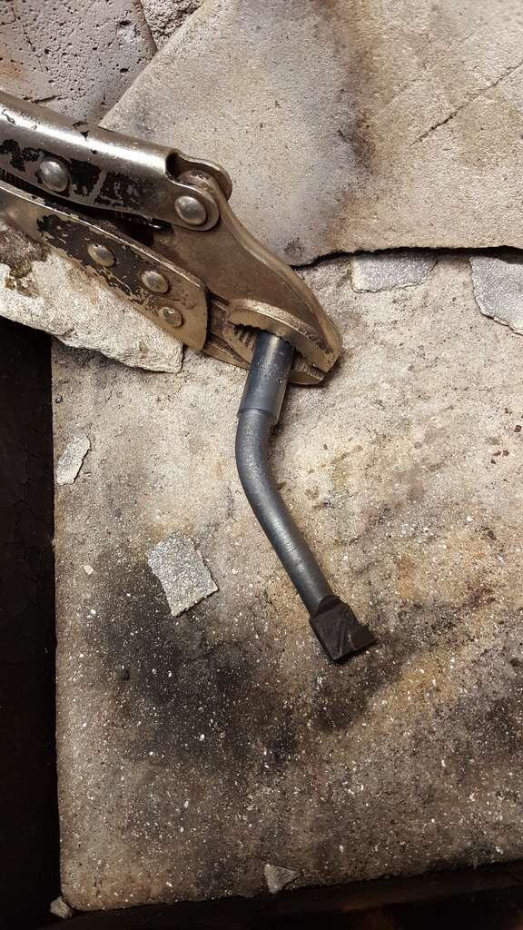
I then started drilling the passageway for the exhaust, I started with a 16 mm to open it up a little first as clearly when cast the plug wasn't central, in fact this cutter didn't even touch one edge of the hole.
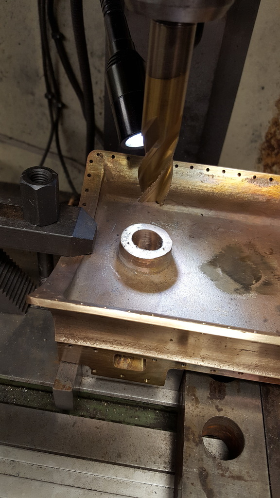
I now needed to open up the passageway to the size specified which is 3/4", now I don't have such a cutter so have gone up a little to 20 mm, I'll call that the 'Roland touch' hopefully some of you will get my jest...
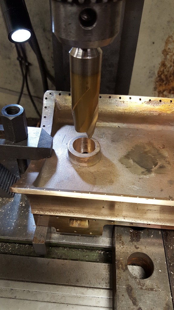
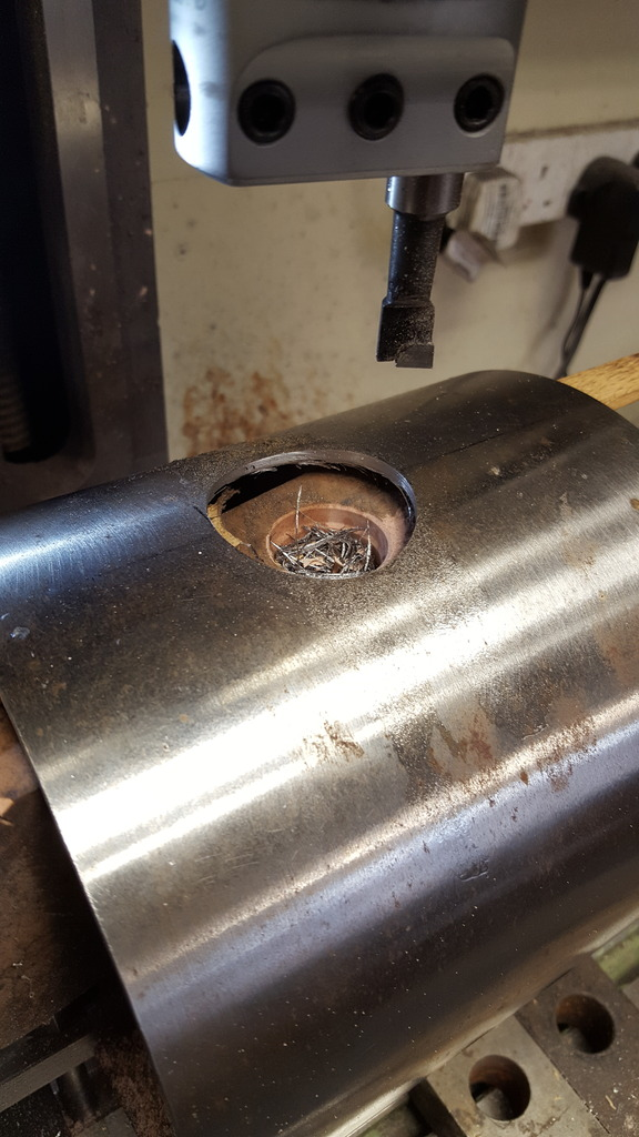
The last job for now on the mill was to face off the top of the standpipe at 3/8", I used the 75 mm face mill for this job , a bit overkill but did the job nicely.
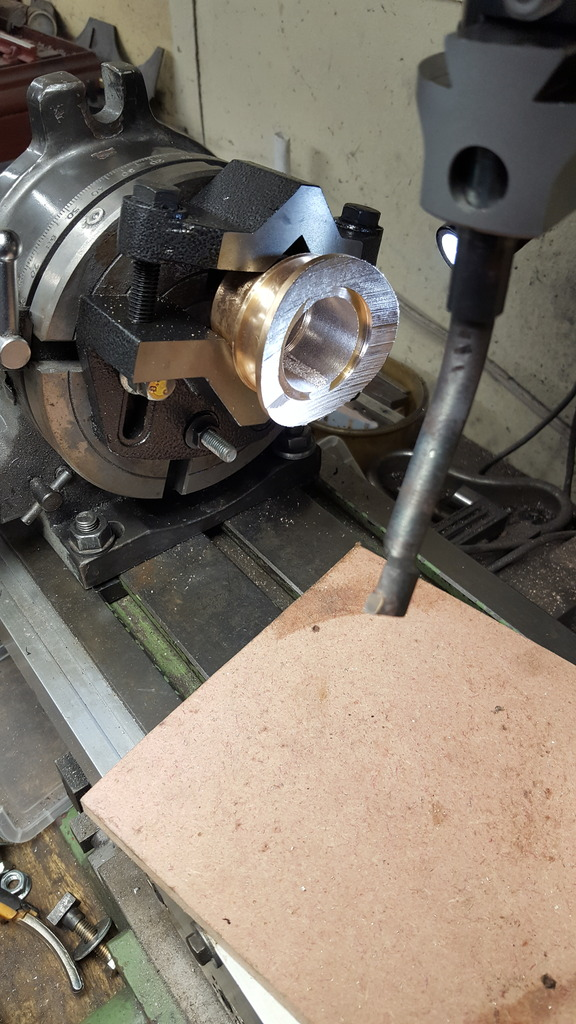
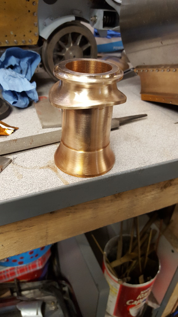
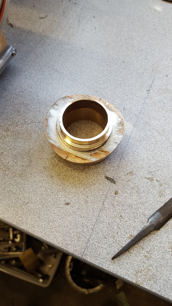
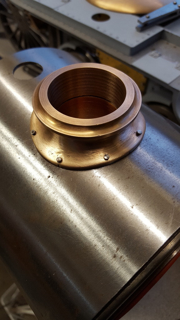
Lastly, I turned up a spigot ready to help clock the saddle into the 4 jaw ready machine the outside of the standpipe to 7/8 ready for threading at 7/8 x 26 T, I had thought about fitting a flange here instead of a thread as per prototype but think it may be a little problematic in getting to the bolts.
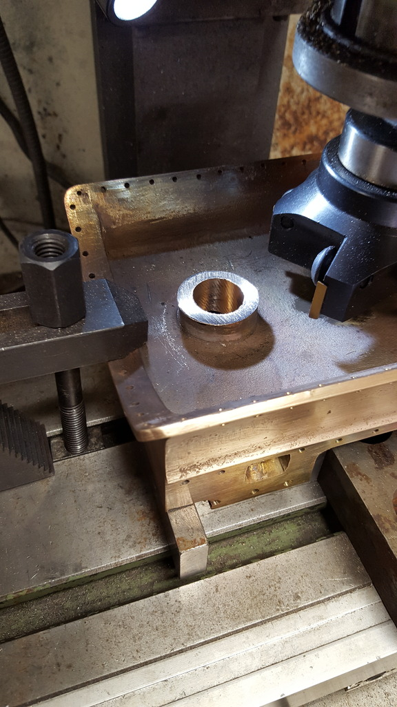
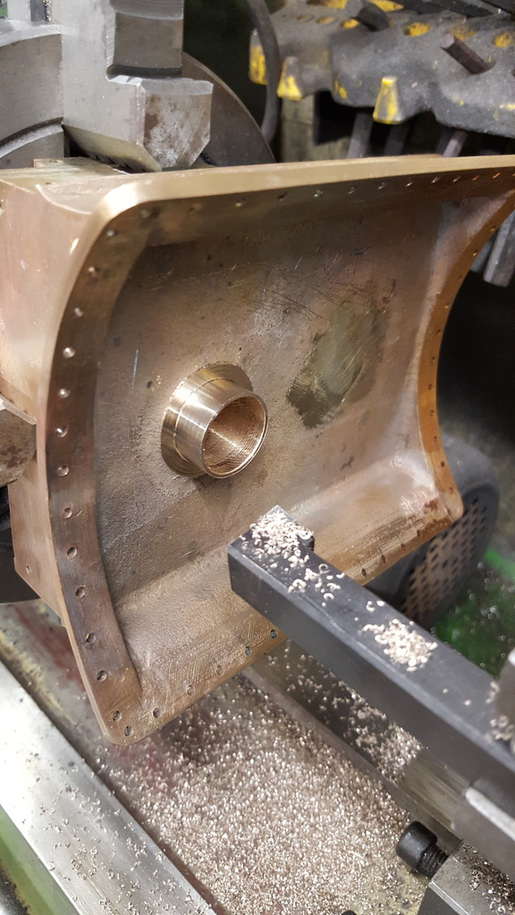
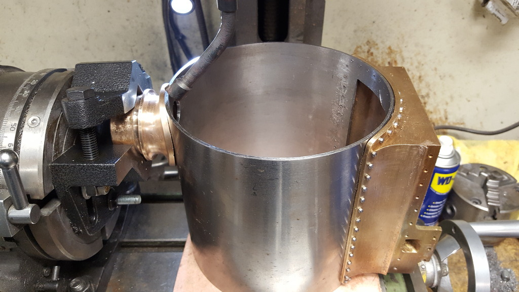
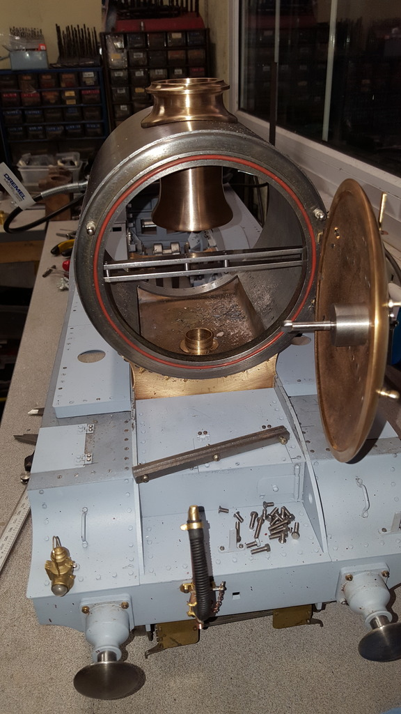
finishing off for this stage I wanted to get the saddle completed as much as possible except for the middle cylinder inlet and outlet openings which will have to wait until I have machined the cylinder's mounting faces. Not much to do then but a little tricky in holding the saddle correctly to machine the outer face of the outside cylinder's standpipe. The job is made a lot easier with the spigot that I turned up ready for this, tonight's first picture shows the saddle centred on the standpipe ready for machining.
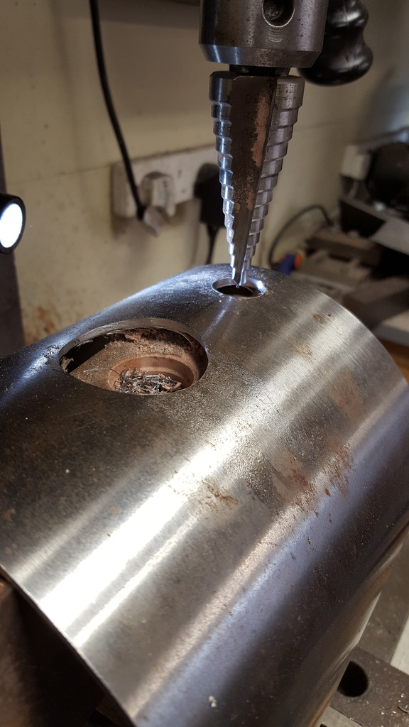
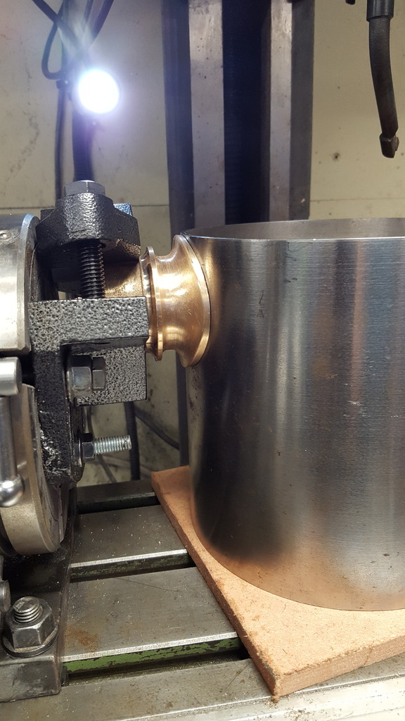
Here we have the standpipe machined down to it's correct size of 7/8 and then a final cut to face off, I have to admit to being a little apprehensive of this stage for two reasons, first as mentioned I didn't have a 3/4" cutter so had to go larger at 20 mm ( in hindsight I could have used the boring bar?) and secondly being as this made the wall thickness much smaller, if I had been off with the boring or machining of the outside I could have run out of material so I was very relieved when this worked out ok, even more so after cutting the 26tpi thread.
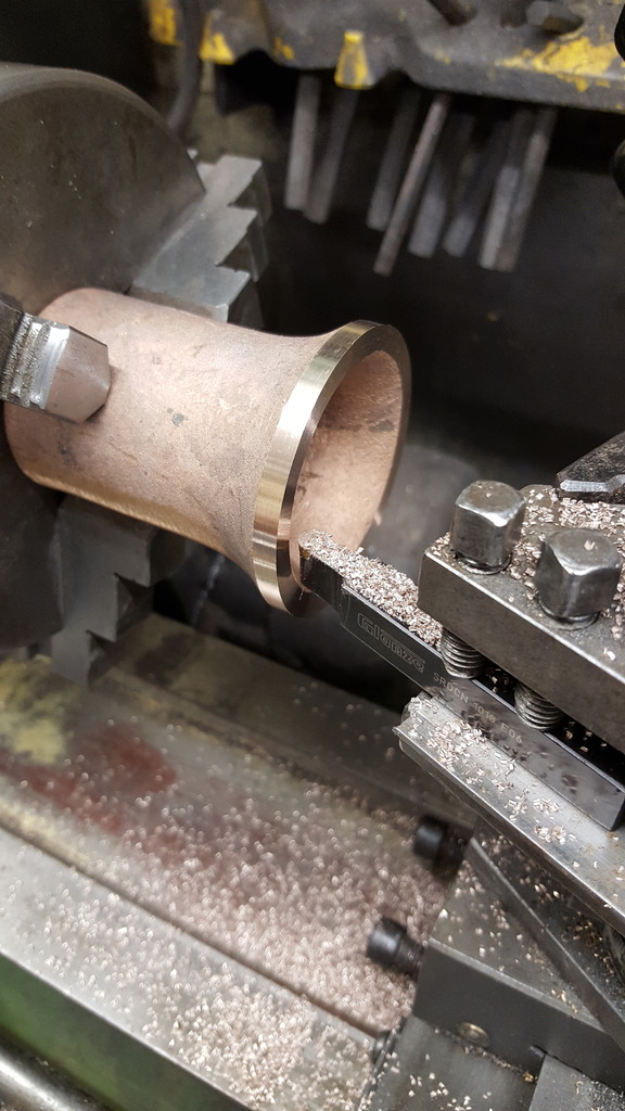
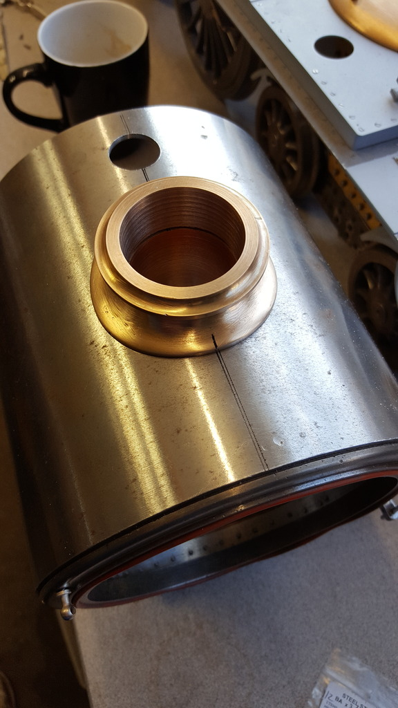
It was then time to cut the standpipe thread (7/8x26TPI), Don states to place a suitable die in the 3 jaw and turn by hand, I wasn't that keen on this in case I didn't get the die square but as it turned out I couldn't do it like that anyway as my chuck is much larger than Don's Myford. This meant doing it by hand, after starting the cut and checking that it was cutting squarely I continued until unable to use just my hand and then used a suitable flat surface to fit inside the die, this worked out surprisingly well.
NB: I reread this and looked at the picture above and wondered why I didn't use the tailstock to hold the die? Either I didn't think of it or more likely the die was too large to fit into my holder?
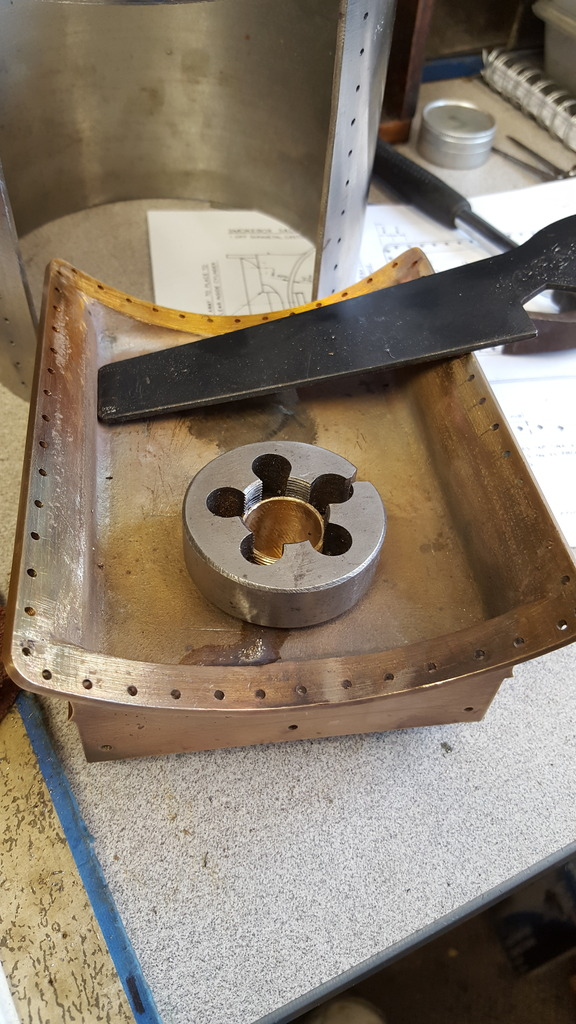
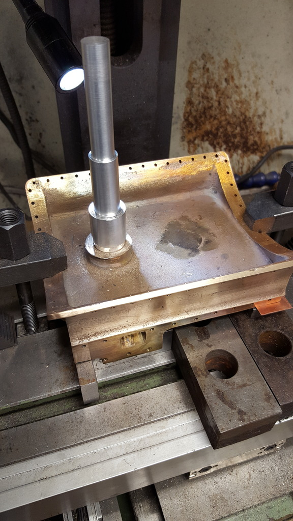
The finished thread..
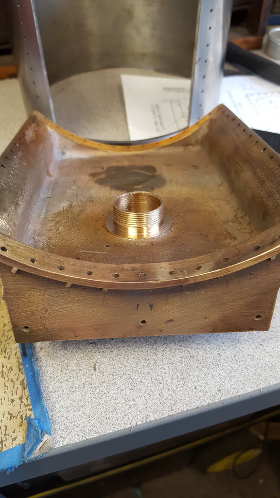
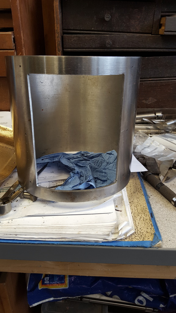
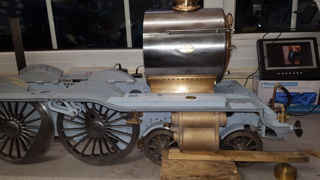
Last picture for this stage, the next job is to machine the openings for both the chimney and the anti-vacuum valve (snifting valve to us laymen) which requires the smokebox tube to be fitted properly to the saddle. I tell you, when this involves 56 8 BA x 1/4" bolts it's not exactly a five-minute job.
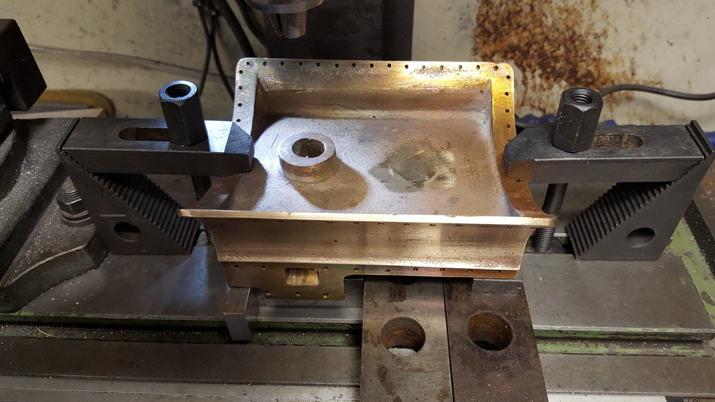
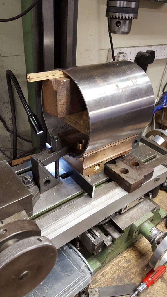
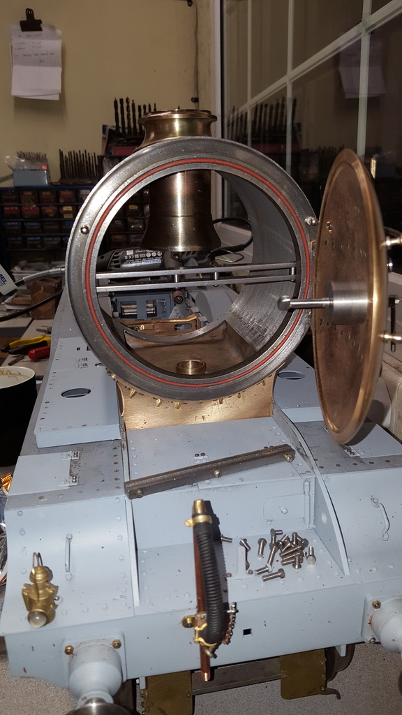
Continuing with the smokebox, the next job was boring the two holes along the top centreline, I did this while attached to the saddle, it's how Don states to do it but it also makes complete sense to ensure that the holes are exactly where they need to be. I first set the assembly up square to both axis and level to the bed, this involved some packing under the saddle. The first picture shows this, note the timber jammed into the smokebox to keep things rigid as this job is a long way of the bed.
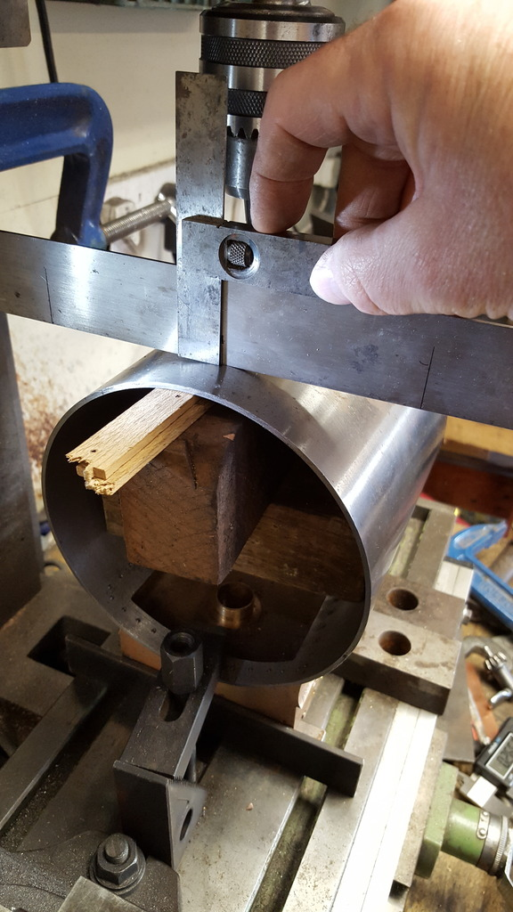
Although I had clocked the centre I also wanted a visual aid as things like this give a strange perspective and I wanted to remove any doubt from my mind as I started to cut metal, I wanted to be sure that not only had I found centre but also that the centre line was parallel with the X axis. To do this I first clamped a large square to the mill pedestal lying across the top of the tube, using a smaller square I marked a line on the large square either side of the tube, I then bisected the two lines to find dead centre and as seen in the picture used an adjustable square to mark said centre line. Then using the large square again, I marked a centre line across the top of the tube, final check involved a centre drill that was used to mark each end of the centre line, as it turned out this required one small tap on the back end to get the centre line parallel with X, probably less than a degree out but out it was.
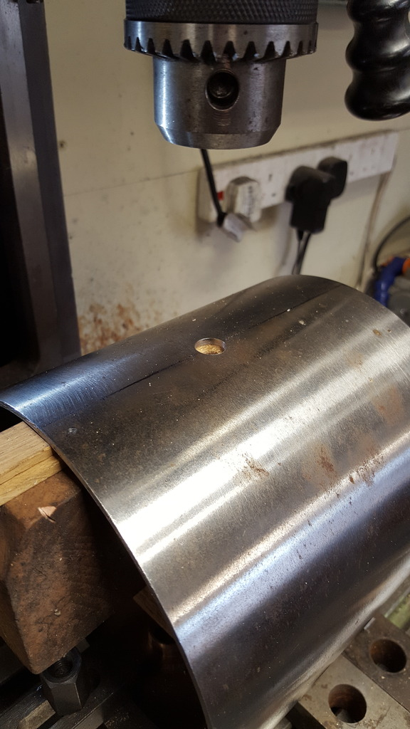
Using an edge finder to clock the front edge of the tube I then moved along the centre line 2 13/16 to mark the centre of the chimney. The picture shows the beginning of this hole having been centre drilled and opened out a little ready for the next step.
The hole was widened more thanks to the use of a step drill, this opened the hole up to 30 mm...
The final size of 1.750 was achieved using the boring head...
I then repeated the process from the other end to machine the anti-vacuum valve opening, I got lucky here as one of the steps was spot on at the required size of 25/32.
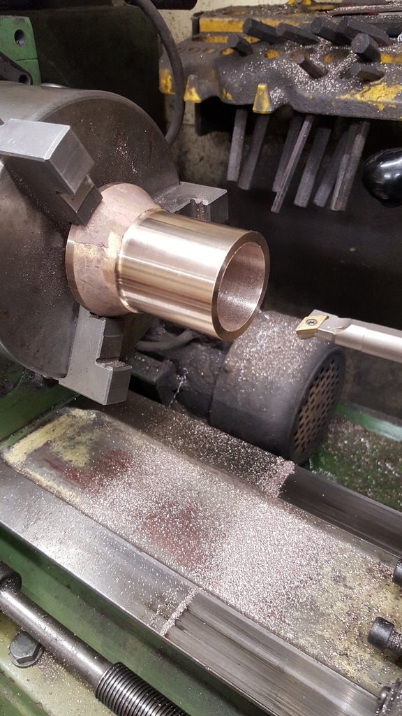
Leaving the smokebox for a while I moved on to the petticoat pipe of which all jobs can be done in the 3 jaw, first job was to clean up the outer edge of the dome to 2 3/8 diameter.
Next job was to machine the parallel section of the pipe to 1 3/4 and face off to a height of 2 11/16, I also started the boring but haven't done the taper yet, I'll leave that for now.
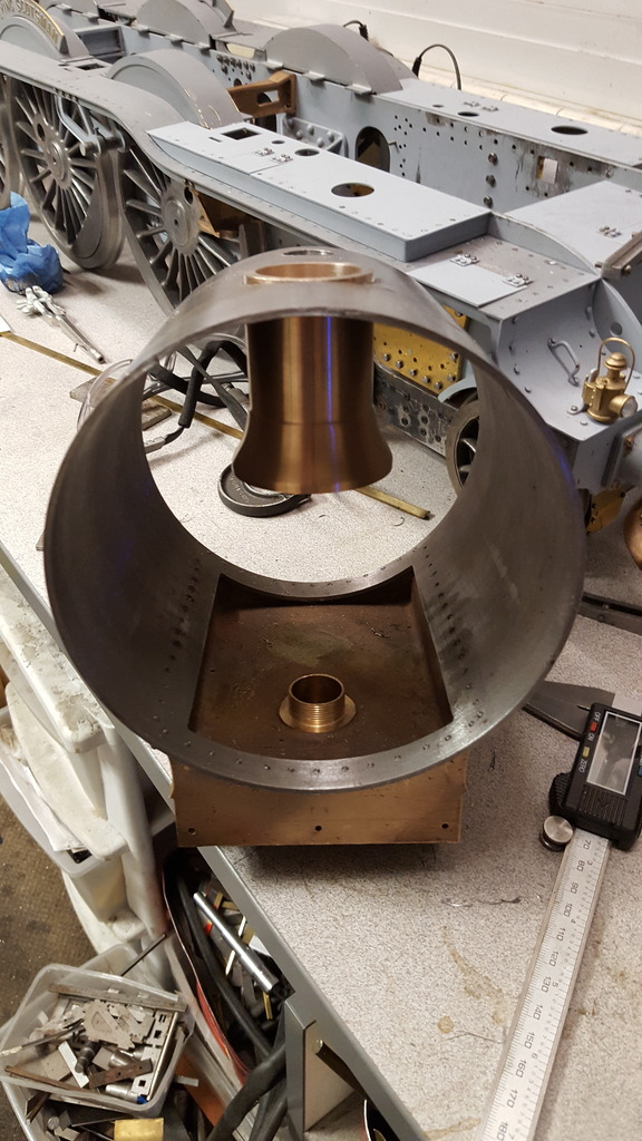
This picture shows the petticoat pushed into the chimney opening, it's a tight fit, it will in fact fit into the chimney itself which according to Don only requires a push fit, I will deviate from this and fix the two sandwiching the smokebox tube between, I'll cover this later. You'll also note that I have made a start on profiling the pipe shape both external and internal.
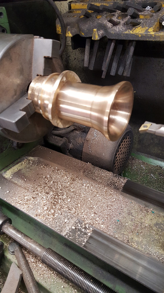
Some more progress on the chimney/petticoat pipe, I haven't bored the internal tapered bore yet, but that's not important right now, I'm still looking at various options for adjustable drafting for the future. So tonight we have the chimney being machined to fit the petticoat and smokebox shell. The first picture shows that the chimney has been machined/filed (oversize for now) and bored in two stages. First was just to clean up the casting and the second was to machine the recessed step for the petticoat to sit in, as you can see in the picture it's a good fit.
I then needed to take care of the underside of the chimney to match the curvature of the smokebox which is a little problematic for my equipment. One, my lathe's cross slide sits too high for me to set the chimney up on the lathe and when I tried the rotary table on the mill using it's chuck, I seemed to have mislaid it's external jaws...lol Luckily at last years Midland ME I picked up a Keat's Angle vice which now came to the rescue. Picture shows the chimney held in the Keats, I found the quickest and easiest way to set the chimney squarely in the keats was to use the smokebox itself.
Now I'm not totally sure why i did this next bit, as can be seen I have heated and shaped a boring bit to give me a larger enough arc to machine the underside of the chimney. Why I didn't fit the bar in the end hole I'm not sure, could be that ididn't think about it or could also be that I wanted to be able to see what I was doing when checking the arc, much easier to do if the boring head isn't in the way. Anyway, i bent one of the bars to suit after heating/tempering and it worked very well.
I then used the smokebox to adjust the boring head for the correct arc and also for centralising the Y axis for the chimney.
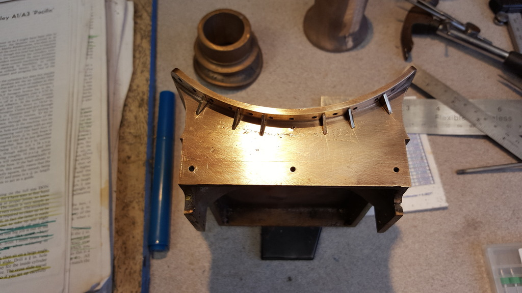
And so the machining begins, now this is not for the faint-hearted and I don't recommend it but it worked and so I'm happy, filing the chimney as Don states to do just didn't appeal. There was no issue with the machining process but due to the cutting tip being so far from the centre there was a distinct wobble to the mill. Although this doesn't effect the cutting as table and pedestal are of course fixed I wouldn't attempt this for anything of a critical nature, for this particular job it was fine. During the machining, I made regular checks to the thickness of the flange at it's four extreme points to ensure that it was remaining equal.
The flange is now down to it's 1/8 thickness, one tricky job out of the way...
NB: The flange thickness was later reduced further to match the prototype.
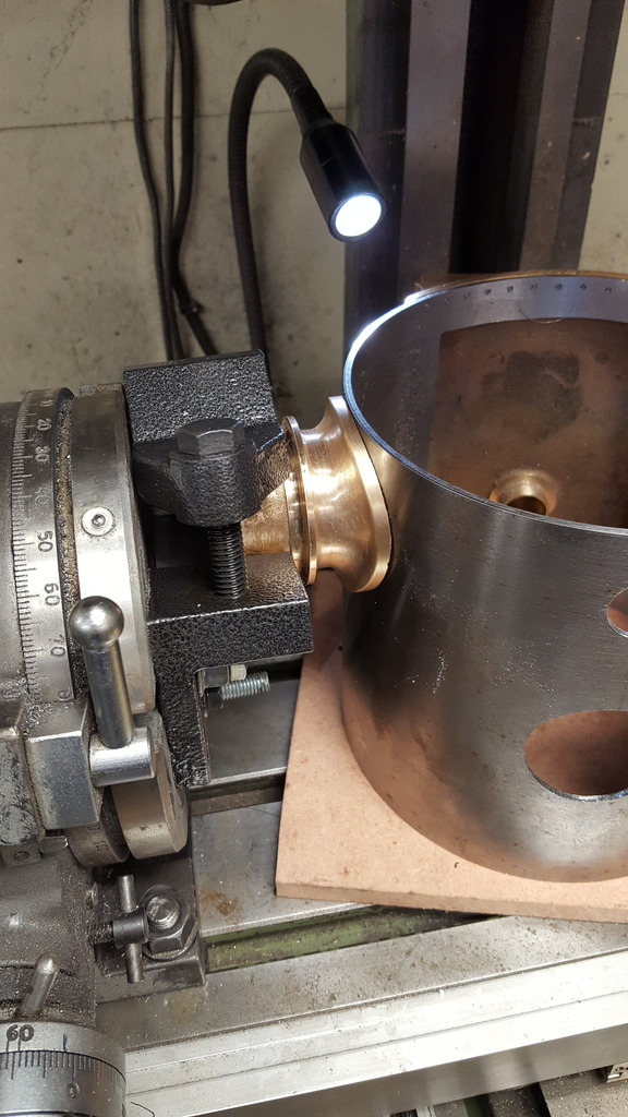
I seemed to have missed an important picture, I did intend to show the chimney and petticoat soldered together and held in the 3 jaw for final machining, guess I was a bit preoccupied to take the picture..lol so here the two parts can be seen still joined after final machining, there is a small casting defect on one edge of the lip (not seen here), I had hoped that it would machine out but was too deep, I'll probably fill this with some solder later.
Now two pictures of the state of play so far, first an interior shot showing the petticoat in position, I still need to finish the profile both externally and internally (will do the taper bore first) so once finished the step seen here will be gone.
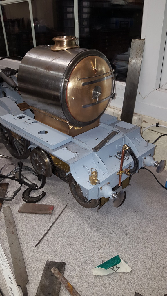
Lastly the chimney in situ, (NB: you can see here that the chimney flange although to drawing is far too thick and was later reduced) other new bits are the door knob (this will be Nickle plated) and the two railing stanchions fitted to the door ring, lot's of fettling still to be done but at least the basic shape of 4472's face is there..
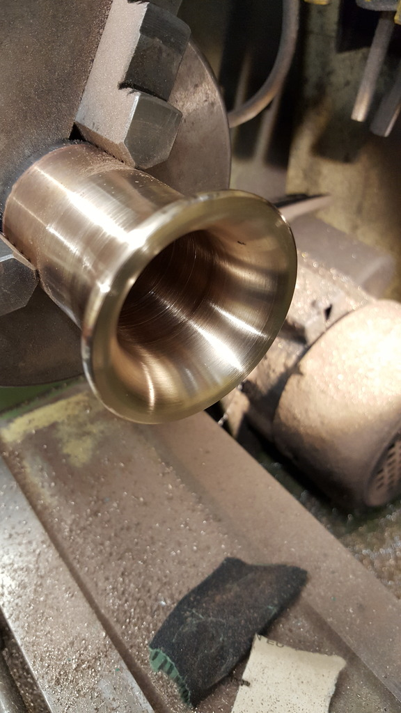
The next few pictures cover the finish touched to profiling the bell-mouth on the petticoat. I first joined the chimney and petticoat together, chucked in the 3 jaw to bore out the 2 degree taper in one hit. This required a little care as the casting gave very little metal around the choke area and on my second casting ( I mentioned before that I was going to do two to vary the draught) the choke was running eccentric to both the bellmouth and the parallel neck section. I, therefore, clocked this one in the 4 jaw to run true with the choke itself rather than as Don states in the 3 jaw, so guys if doing this locomotive do check this casting very carefully. The other petticoat will have a parallel bore where I plan to fit inserts of varying tapers to match different sized blast nozzles and also different exhaust manifold heights to match, fun and games ahead there then. So first picture shows the petticoat after machining and filing/sanding. the mouth opening is 2 3/8 diameter, the choke is 1.350 and the chimney opening is 1.510. The choke is a fraction lower than the 1" shown on the drawing, I took the bear minimum off this end but it had been ground by reeves on both ends and I guess the drawing wasn't checked, I can adjust the nozzle height if so required, again that will be during draft testing which is a long way off.
This picture to show that the outside profile is also finished, the pipe itself still needs more work in the form of the 'ejector' collar that fits around it, I would have machined that up for this update but discovered that I have no brass or bronze large enough (2 1/4") for this job in stock so it will have to wait for now.
The chimney still needs it's mounting holes drilled, Don, states that the flange was fixed to the smokebox via 8 x 1/4" bolts with nuts on the inside, over the weekend I'm going to have a look at my reference pictures to see what orientation these are, in relation to the flange shape. I won't be using nuts, though, too problematic, there's an inner flange that fits around the petticoat, my plan right now is to have the bolts go right through the smokebox into tapped holes in this inner flange.
NB: I still have to do this inner flange.
Chimney continued... after searching through various books I concluded how the 8 bolts are positioned around the chimney flange, not easy finding close ups of the chimney but I remembered seeing just such photo's in the RCTS part 2A, not of 4472 but I see no reason for the chimney to have been fitted differently from other pacific's. Having decided that the bolts start 22.5 degrees off the centre line I needed to first mark the chimney's flange centre in relation to the top centre of the smokebox. The first picture shows this being done...
I then needed to hold the chimney in the rotary table chuck ready for plotting the eight bolt holes and I needed to do this from the top so that I could see clearly where the bolts would be going in relation to the flange edge. To do this I first turned up a spigot to be a good fit in the chimney. Picture shows this, note that I have marked the centre line under the flange, this line continues to the top.
Next job was to mark the holes, I didn't drill right through as the holes would be at the wrong angle, I just used this to plot their positions ready for drilling through properly which I later did by holding the flange flat on a piece of wood whilst drilling. The method used was to start from the flange centre line, move 22.5 degrees as a starting point and set to zero and then plot each hole 45 degrees from there.
Finally, we have the chimney bolted to the smokebox, I haven't secured the petticoat pipe yet. The holes were first drilled 1.4 mm, the chimney was held in it's correct position and the holes were transferred onto the smokebox, drilled and tapped (for now) 10 BA, the chimney holes were then opened up to 1.8 mm for clearance. Once I get around to securing the petticoat pipe to it's mounting flange the smokebox holes will be opened up to 1.8 mm and the inner flange will have the holes transferred to it to be drilled /tapped 10 BA, as with the smokebox to saddle this will be sealed with a bead of heat resistant silicone.
I was in two minds about these bolts as Don said to leave them off as in his words 'he's yet to see this done that looks right'? strange thing to say, anyway I think they look ok, the only difference that I can see between the prototype and model is that the flange may need to be a little flatter, I'll try to find a picture of 4472 herself before making any changes just in case chimney patterns varied. Next I shall fit the handrail stanchions and mark out the ejector elbow, I need to find either a drawing or better picture of this as Don's drawing looks a bit simple, I'm sure there's more to it than drawn.
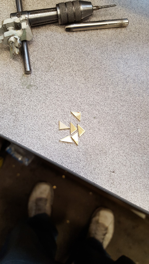
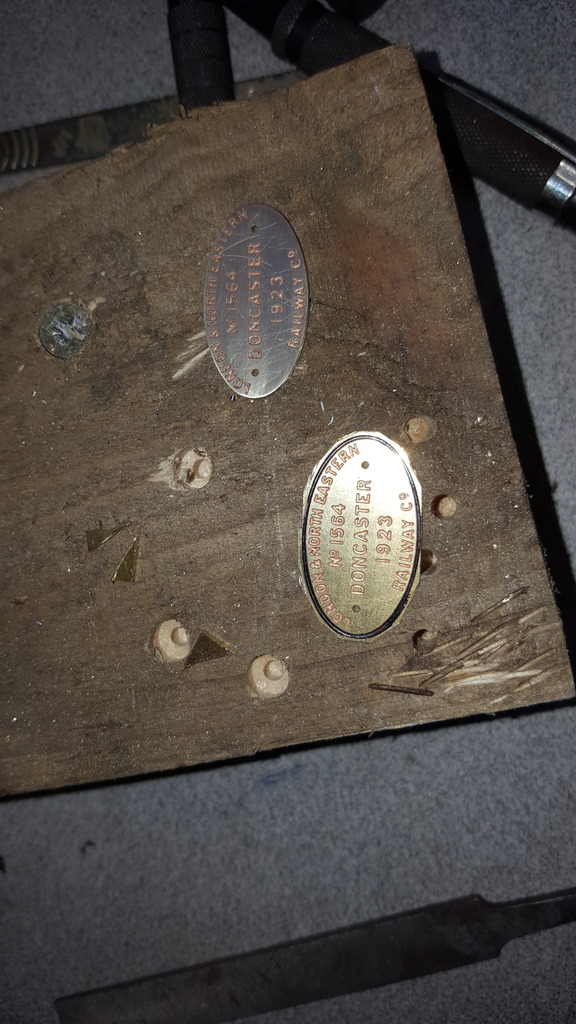
Well I've been playing around with details today, just felt like doing a little bit of chilling and so have taken a look at the builder's plates and train board, the builders plates I've had for a while kindly etched for me by Diane Carney before she took over as editor of Model Engineer. these needed cutting out from the brass sheet, I used a slitting disk to get close and then finished by hand with a file, picture shows one of each.
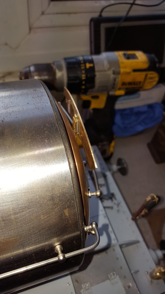
Next, a simple job which was to fit a bracket to the back of the name board that fits over the lamp iron. Easiest way was to use a piece of brass square section K&S, squeeze one end so that it's a loose fit over the lamp iron and then solder it on. I first found the centre of the name board and then ascribed a line that was square to the arc. Leaving the brass tube over length (it's easier to eyeball that it's square to the centre line) I clamped it in place and then soft soldered to two parts together, no need for silver solder here.
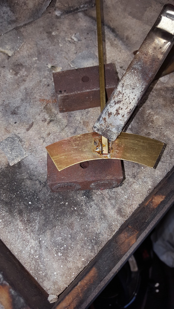
Once cleaned I then tapped the top of the bracket down at an angle with a small hammer to close it up a little so that it holds itself nicely on the lamp iron, this way you won't take the paint off the length of the lamp iron when pushing it on.
Here's a view of the head board from the front, I had discussed which board to have with Diane some years back, in fact, she sent me two to choose from, 'Flying Scotsman' or 'Night Scotsman', I went for the later, you see a lot of models with the former but not many of the other (that's a mouthful)so here it is. If i get around to that rake of Gresley teaks that I want to build after 4472 it should suit a night run with all the carriages lit.....
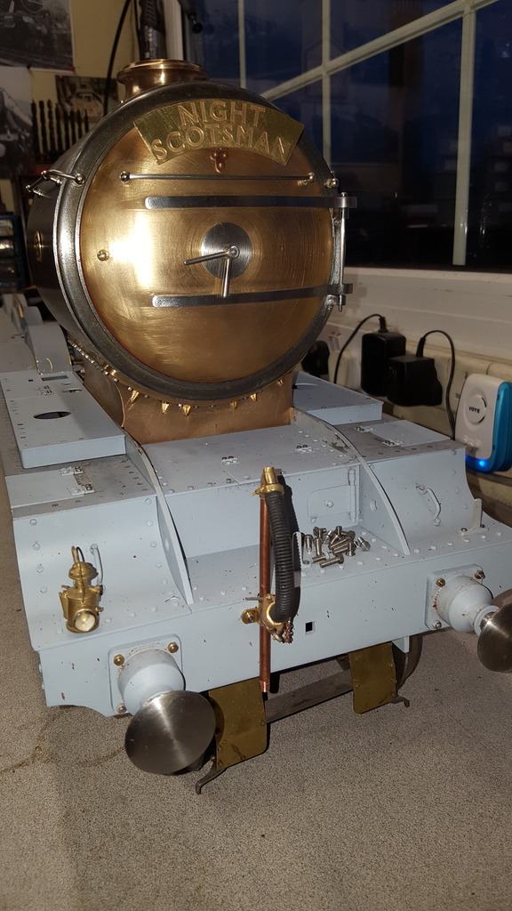
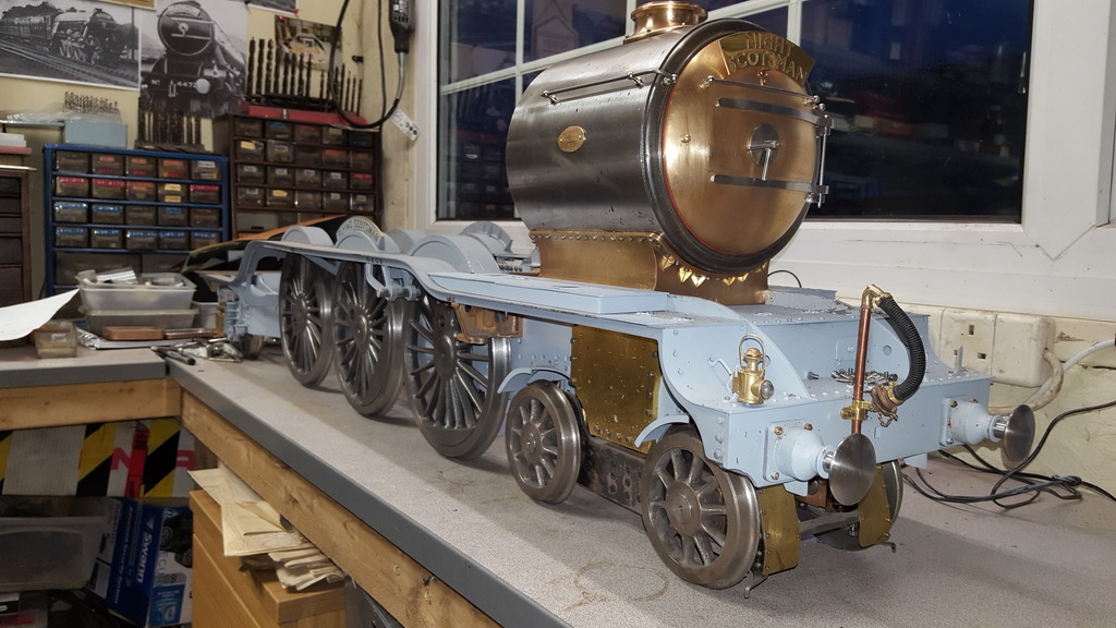
With the smokebox back in position, I took the opportunity to check the cylinder for it's relation to said smokebox, all looks good, very good in fact with the steampipe opening in the upper running boards lining up nicely with the cylinder inlet area. I have deviated in the positioning of the builder's plates from how drawn by Don, he has them set forward of the chimney centre line and lower but the photo's that I have clearly show the plates central with the chimney and higher being pretty close to the 'Ejector' elbow, which BTW I have piloted a hole ready for when I have machined the elbow, I later had a chat with Adam (CRO fittings) who drew up and 3D printed/cast a lovely elbow for me, now part of his fabulous range, more on this later.. Another point to note is the handrails, I've looked at lots of photo's and they all seem to vary a little, some are at the same height as the stanchions on the door ring, others lower and others as I have done, are above, in fact I have pictures of 4472 that seems to show all 3 positions? perhaps they get bent in service?
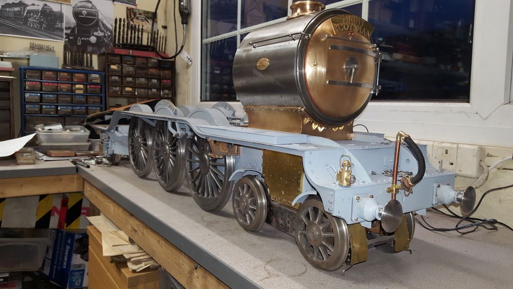
Lastly a 3/4 view of progress from the front,