

Smokebox etc...
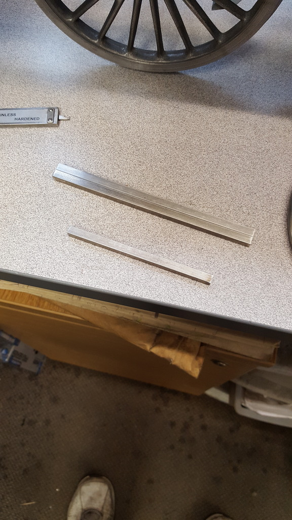
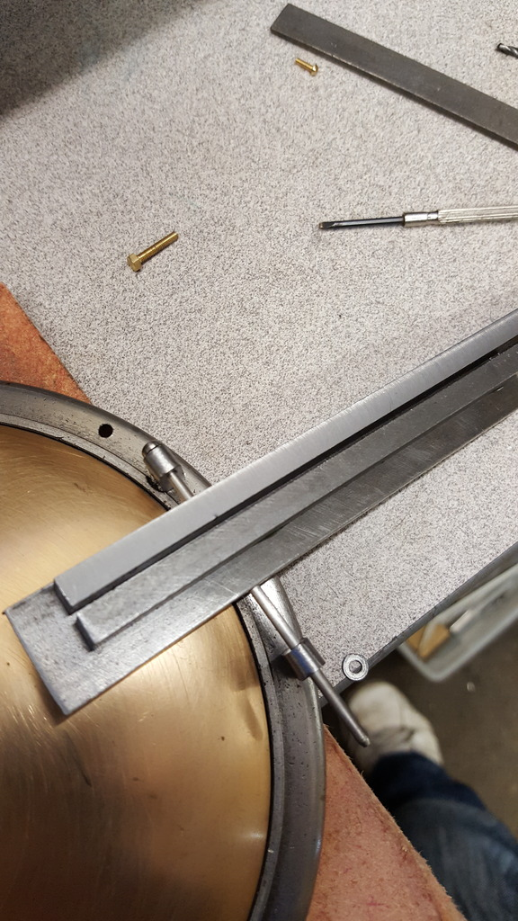
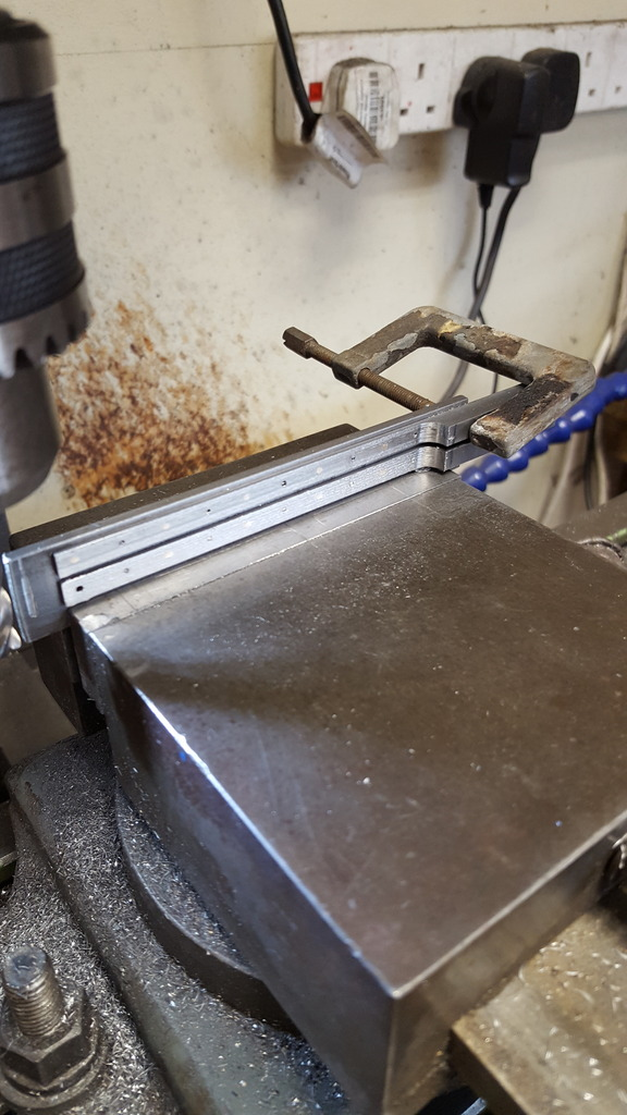
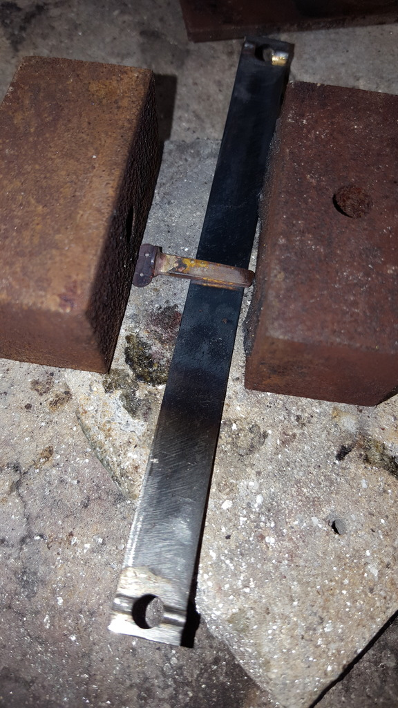
On 4472 for my era the door hinges etc were burnished steel, I will use stainless steel to represent this look and also to remain looking this way with no corrosion, well that plan changed when it came to tapping some holes but I'll explain that when I get to that part. First picture shows 3 lengths of (yes stainless steel) having been machined down to 7/32 square for the short length and for the two longer lengths 7/32 x 6 mm, ( Don states 7/32 sq for all three) the material started off as 6 mm square. Now I have shown this picture of the stainless purely as I failed later to take a picture of the BMS that I remade these parts with after trying to tap them 10 BA. I had no problem machining them to size (thank's to a nice new special cutter( forgot type) that my son borrowed from work just for this job. Tapping was another thing even after opening out the tapping holes by approx 65%, the problem being that I don't own a 10 BA spiral point fluted tap and they aren't cheap? so I changed to BMS which I shall burnish to finish to help stop any corrosion issues.
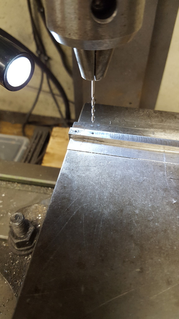
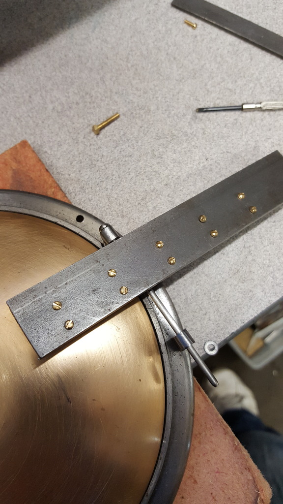
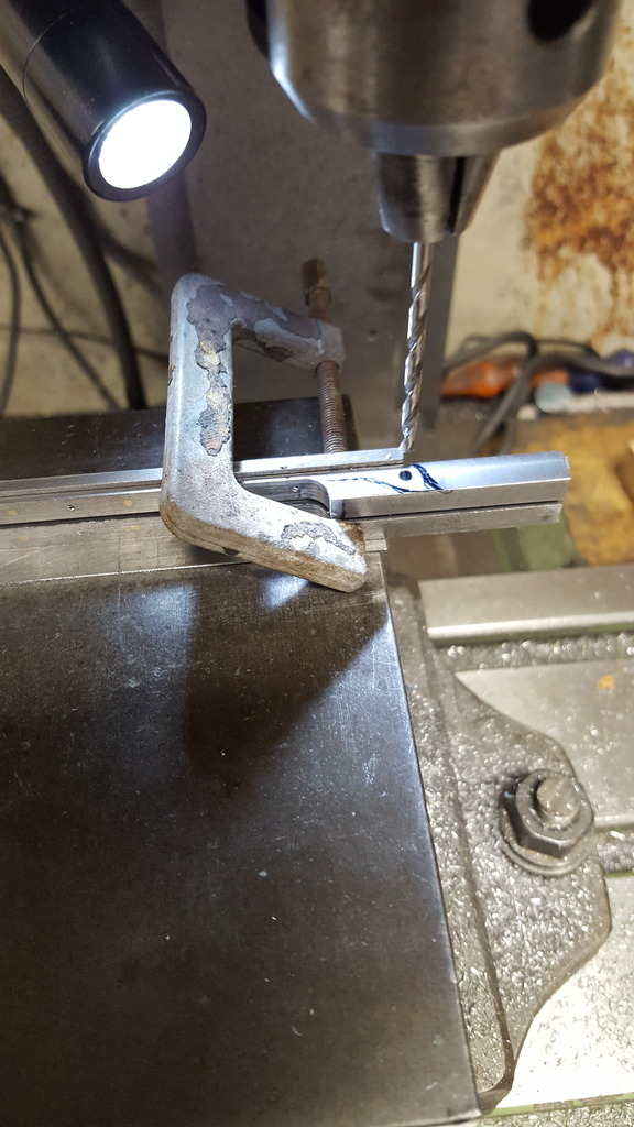
Next, I needed to drill the holes for the rivets to secure the hinge to the door, these will be for 1/16 steel rivets but for now I have drilled them 1.4 mm to take a 10 BA tap, reason why will become clear soon. Don stated to give this a 1/2" pitch but on scaling from photo's this didn't add up and so I reduced the pitch to 10 mm.
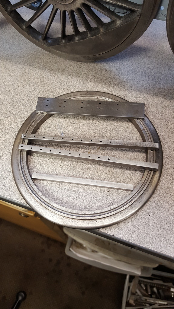
This is how far I got before scrapping the stainless steel idea and remade these parts from 3/8 sq BMS. The flat bar shown here with the 10 holes drilled in two lines of five is a holding jig for the hinges, more on that later.
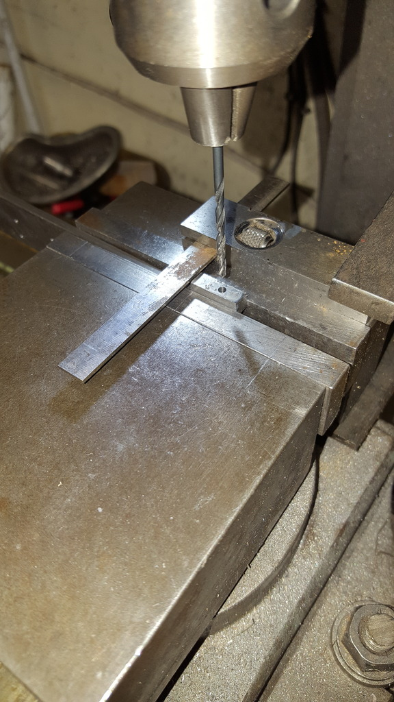
On to the hinge blocks, this is what the shorter length was machined for, it was way over length but that's because the original plan for these was to clock the bar in the 4 jaw and turn down a length to be the spigot that fits into the mounting holes in the door ring, last part being threaded 6 BA for a securing nut and then part off to size. Well that was the plan, alas I hadn't given any thought to whether something this small would fit into my 4 jaw... yep you guessed it, it didn't...lol No big deal, I cut off two lengths slightly oversize, clocked in the machine vice for centre drilling one end 2.85 mm ready for the spigot/thread to be turned up and silver soldered into the block. Next job was to cross drill the hole for the pin which is 3/32 diameter (No.42) up 3/8 from the bottom of the block. Last job is to round off the end which I did by hand using a 7/32 dia button. I then silver soldered the parts together to complete the hinge blocks, finished blocks can be seen in later photo.
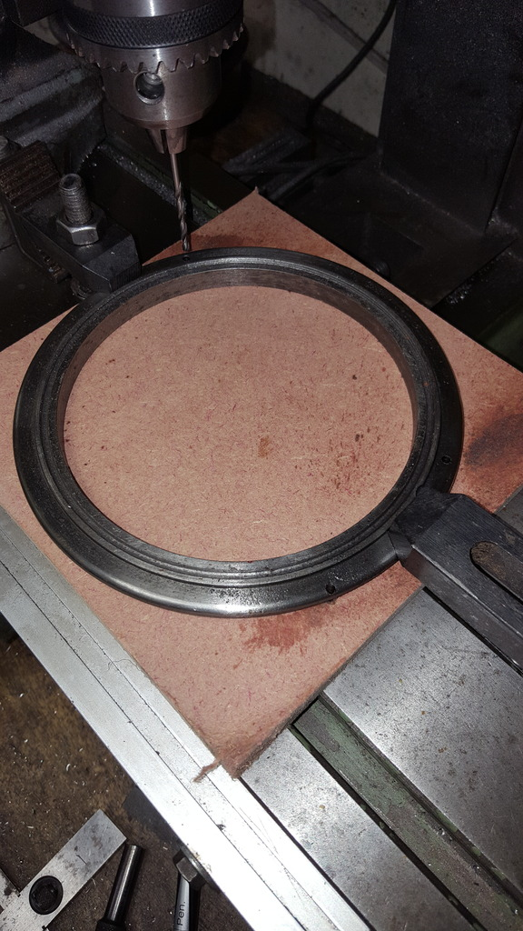
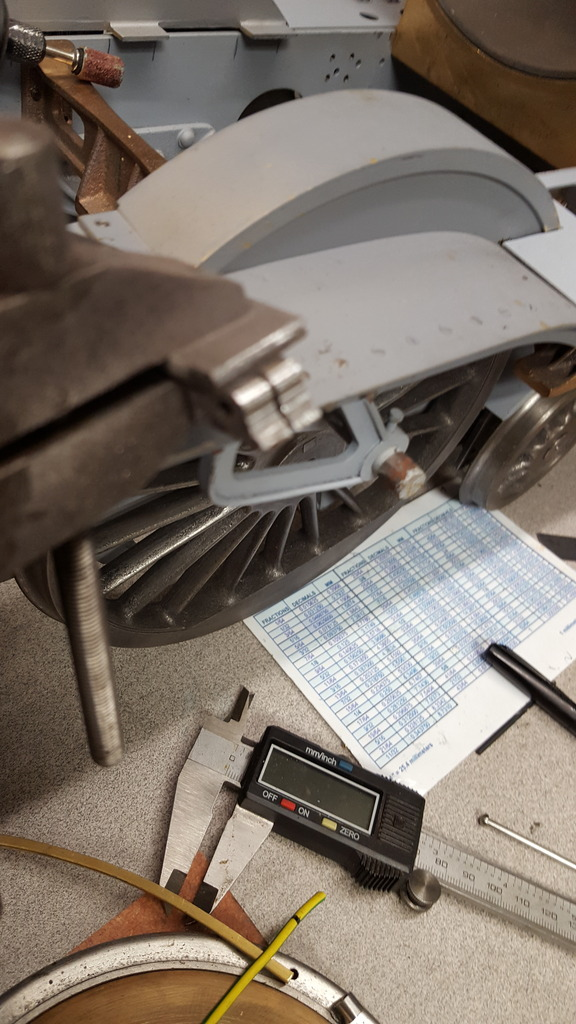
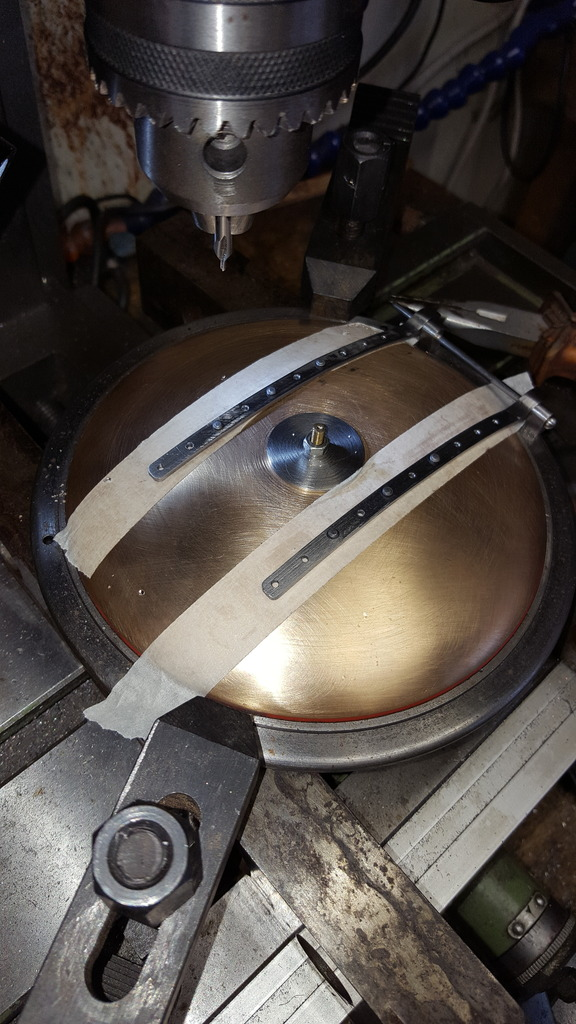
On to the door ring that needed 4 No.34 holes drilled, two for the hinge blocks and two for handrail stanchions. I clocked the door ring to find centre and first drilled the two hinge block holes, these are drawn as 2 49/64 to the right, top one is 0.6718 up from centre and bottom is 1.1093 down from centre. Now something didn't quite add up here, the holes seemed too far out to the edge, I knew that the lower hole was literally on the edge anyway but things didn't add up. I quickly checked the centre opening which was spot on at 5", the flange which was also spot on at 5 5/8 so clearly the measurement given couldn't be right, more so as my outer ring dimension is bigger than the drawing anyway which should give me more space...strange?....BTW for those who haven't followed from the beginning or perhaps forgotten, I made the ring larger than Don's drawing which gave too large a step between ring edge and outer smokebox tube, I used photo's from my chosen era to decide on a size. Some will remember that it was during this time that we discovered that today 4472 has a new door ring which is nothing like her original, in fact, it's ugly in comparison...IMHO of course...
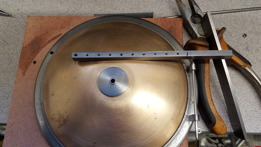
After drilling the hinge block holes I next drilled the two stanchion holes, these are 1 9/32 up from centre line and 5 3/16 apart.
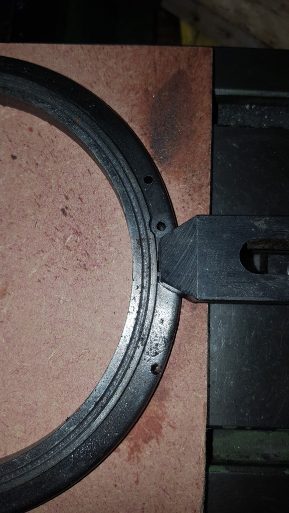
The top hinge block hole then needed a 5/16 diameter counter bore machined into the flange to clear the block, you can see how close the lower hole is to the edge, I used photo's as a guide for where to place these holes, they seem different to what they were before preservation.
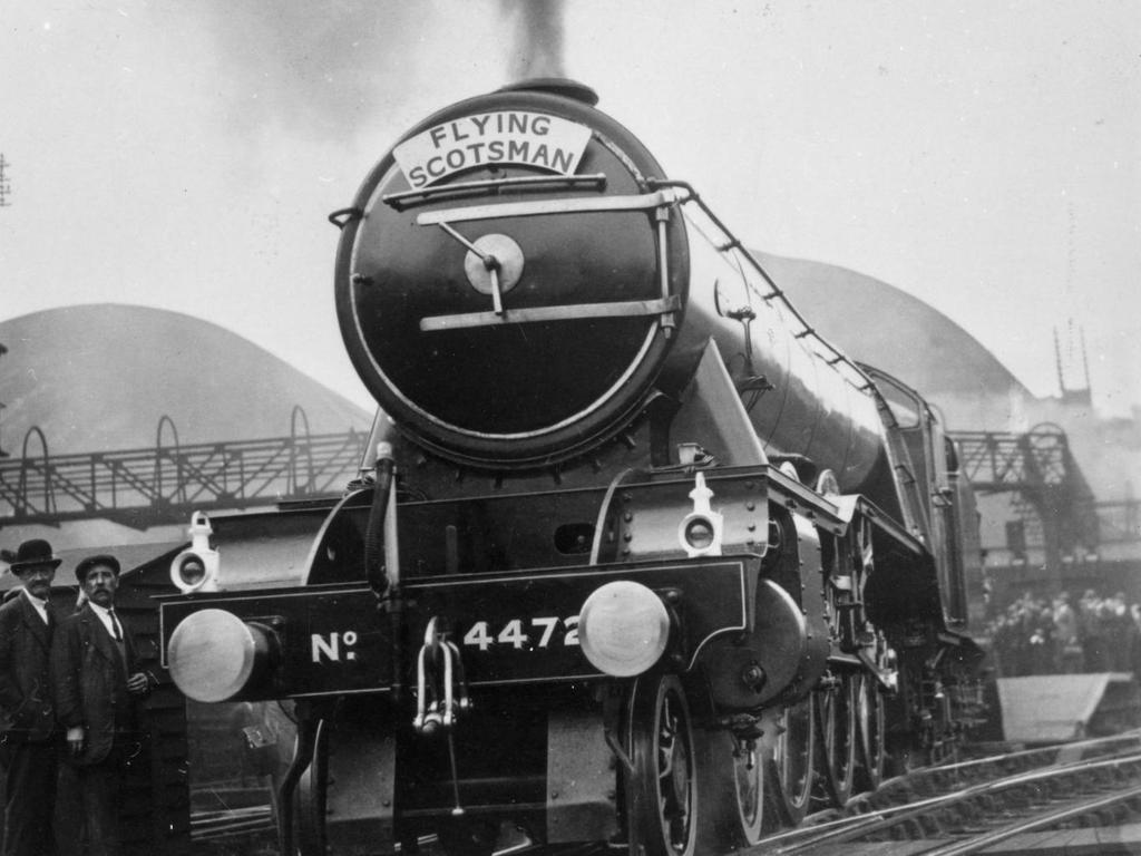
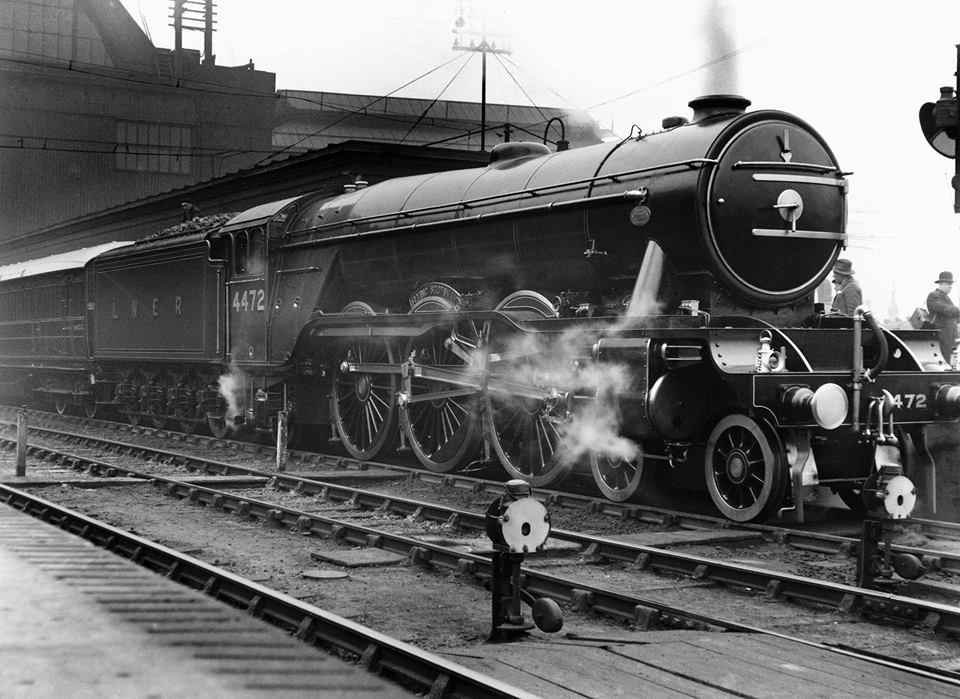
This is one of the pictures that I've used as reference, you can see how the lower block is literally hanging over the edge, i'm not sure if the block maintains it's square shape of if it's chamfered, I suspect it's just square, either way, I can modify it later if required.
I now needed to temporary fit the hinge blocks using the pin to square them up and them check that the hinge was looking right for the next stage. I first marked the door 1 13/32 from cente to the left which is how far the hinge goes across the door face, laying the hinge roughly in it's position I checked that it looks right for the mounting holes and for where I need to machine it down to a thickness of 1/16, Don states over a length of 4" which is where the black line is drawn between the last hole and the hinge block. There's a lot more work to do here but things so far are looking good.
This is where the 10 BA tapped holes and the jig become clear, I tapped 5 holes in each hinge plate 10 BA for securing to the jig plate, here we see the two hinges fixed to the jig
picture of the reverse side showing the brass bolts holding everything together..
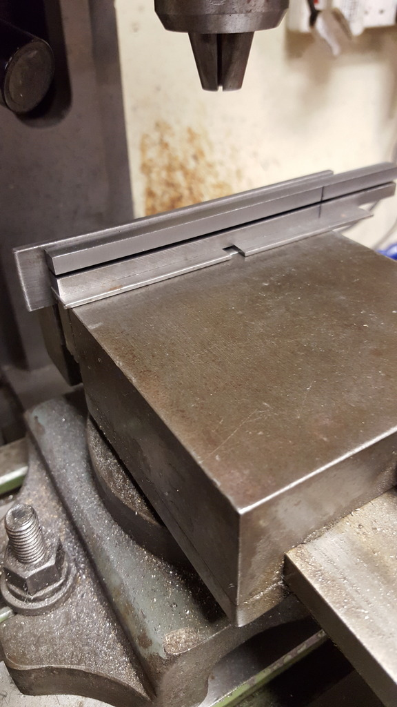
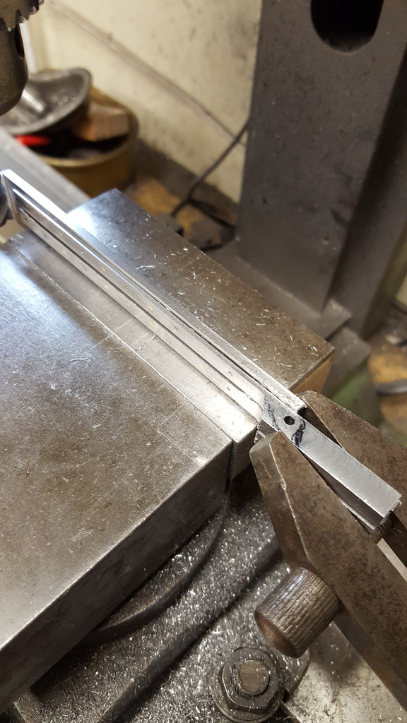
Last picture for this day shows the jig held in the machine vice ready for machining, I left it as this stage as I have used small dabs of loctite 638 as extra security in holding the hinges to the mounting jig and I wanted to give it time to cure.
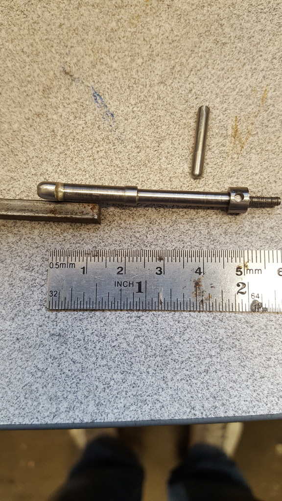
Ohh.. I forgot about the hinge pin...made from two parts, first being the stem which is 3/32 with a taper on it's end and the top cap which started life as a section parted off from some 3/16 stainless steel bar, centre drilled first to fit the stem, once silver soldered together the stem was put back into the 3 jaw and the cap was shaped as a flat dish which is 5/64 high.
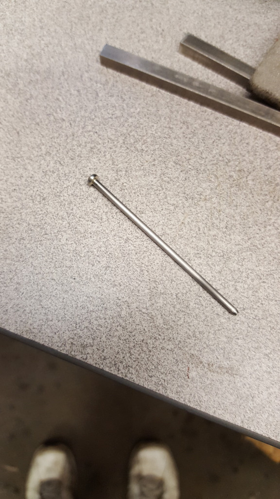
Currently, the pin is a little over length, I'll reduce it once the door is finished. A little more progress and another small change from Don's drawing.. first job was to machine the hinge straps to their required thickness of 1/16", I stopped a little short of the 4" stated by Don as I wasn't sure how this would work out since I was trying to follow the full size profile. Picture shows the two hinges still attached to their jig after machining, I was happy to get to this stage without any problems, it would have been a disaster if the screws and Loctite had failed during machining.
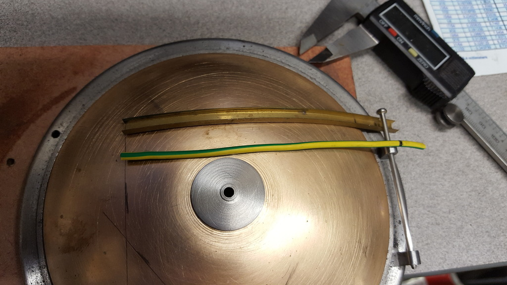
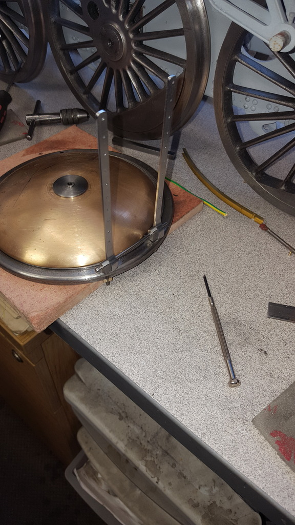
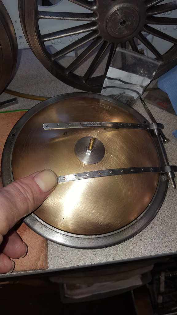
Before cross drilling the hole for the securing pin I needed to ascertain the exact length of the hinge strap and the position for said hole. Using some brass channel I carefully bent it to follow the shape of the door and marked where the pin was in relation to it. Then using an off cut of wire I marked out the length around the curve so that I could transfer the distance onto the straight hinge strap. Also of note is that I have changed the hinge blocks, or should I say I've modified them from what Don has drawn. The drawing shows the pin centre as 3/8" up from the bottom of the block, when looking at how the hinge straps sit in relation to the pin and the door it was clear that the pin was sitting too high off the ring face, pictures confirmed that I needed to reduce the height of the blocks, I judged this to be just over 1/8" and I'm now much happier with how it looks, more like the prototype which clearly shows the pin being much closer to the door.
With the pin hole plotted, I drilled the hole and roughly marked out the shape around it, clearly I needed to do a little more machining.
Shortly after I had finally finished the machining of the hinge, now over to doing things by hand
Sorry about the quality of this picture, I have shaped the rear of the hinge strap leaving only the small front section left to do, there is a slight difference between the two hinges at the front which I'll take care off soon.
A point of interest, while looking through a fair few pictures of 4472's smokebox I noticed that she hasn't always had these hinges, her early ones didn't have the lug extensions, I don't recall noticing this before, mind you that doesn't mean anything....
Continuing on with the smokebox door, here I have finished the hinges and attached them to the door..this involved first shaping the hinge pin end which was done with a sanding drum and some hand filing and then drilling through the 10 BA tapped holes to open them out ready for 1/16th rivets, finally, a small counter sunk to seat the steel rivets. First picture shows how far the hinges open with their end lugs (slightly different lengths) touching the door ring. From what I've read the lugs were added as a safety feature to stop the door from swinging fully open.
Next the hinge strap being part shaped via hand to match the door, takes a little time as it's a compound curve but it's only a gentle curve so no real problem and the rivets will hold them tightly in place.
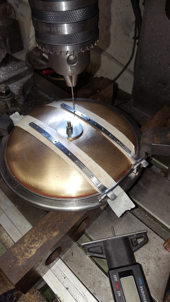
Once the hinges were shaped I re-clocked the door ring on the milling table sitting on some parallel bars, taped under the hinges to stop any slip on the 1/16 drill bit, lined up with the centre of the hinge strap near the hinge block and then once happy that all was square I moved along 'X' to one of the centre holes in the hinge strap and drilled the first hole through the hinge into the door. I then placed a rivet to hold in place and moved along a few holes and drilled another, doing it like this helps keep the hinge straps running at 90 degrees to the hinge pin, or at least that's how I tackled this particular job. Also of note is that the door sealing ring has been put in it's groove so that the hinge is in it's correct position for sealing the door properly.
Once the central hinge holes had been drilled (the outer holes have to be done by hand off the table due to the angle) I then moved to plot using a centre drill, the door handle point, two stanchion points and the lower central rivet hole for the door lamp bracket.
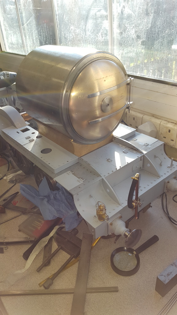
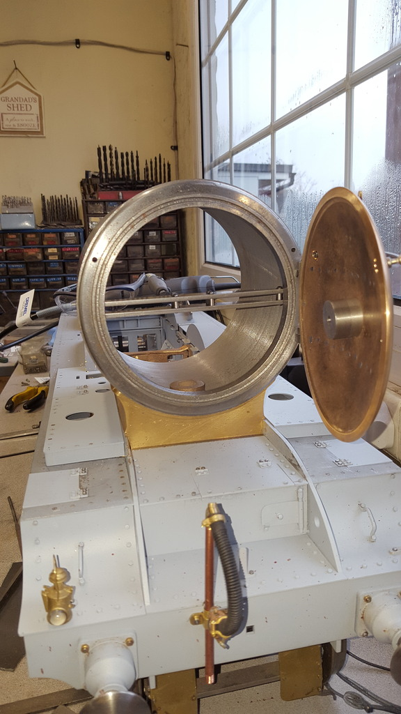
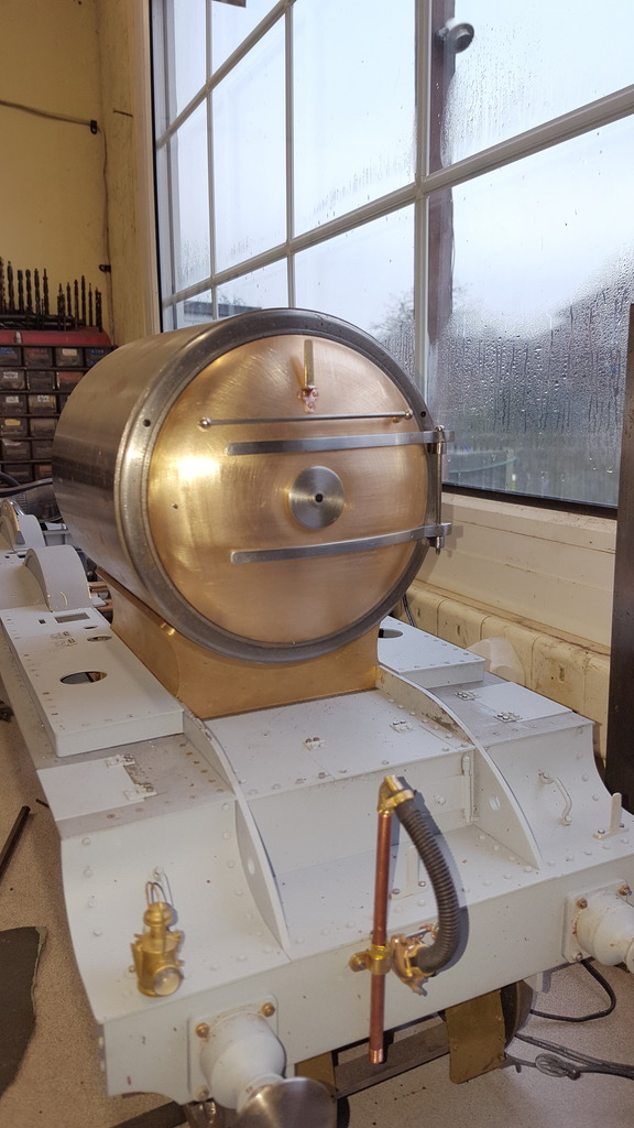
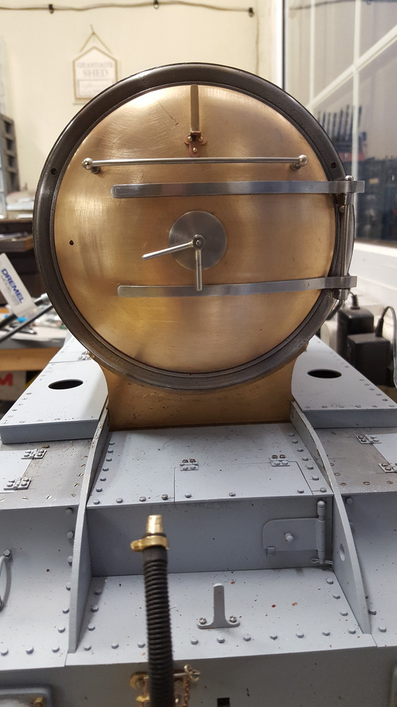
A few pictures now to show the door in place, here with the door closed... (please excuse the quality, unfortunately, the sun was facing the lens)
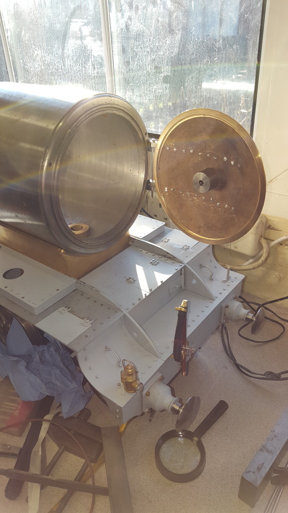
Next, the door opened as far as the lugs will allow, the centre boss has been left this deep for me to fit the inner ash shield as per prototype, this will be another little extra deviating from the drawings.
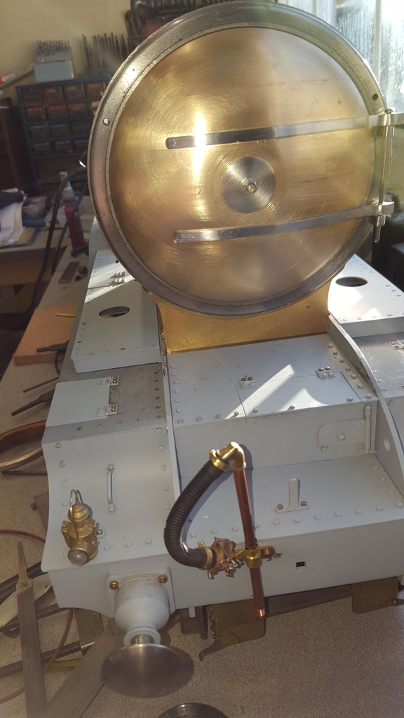
Now, a view looking a little more head on, here you can see that the hinge lugs are of two different lengths as per prototype, this allows both lugs to hit the ring at the same distance, well it does on the model, I'm assuming that the prototype is the same...
Continuing with the door I have now fabricated some of the ornaments as Don calls then, first was the lamp iron, Don gives two drawings, I need to use the early pattern for my era. I shaped the base from a sheet of 1/32 copper sheet, drilling the 3 3/64th mounting holes in a triangle shape which have 3/16 spacings and 3/32 semi-circles cut around them, the top had a 3/16 tab that's folded down and sticks out 5/32. The lamp tab itself I silver soldered on, this started life as 1/16 thick flat brass that was tapered on both faces. The first picture shows the two parts after silver soldering together, the old leaf spring was used to ensure I had the required step back from the rear face.
I then tackled the crosspiece support brackets, these are simple joggled shapes that were screwed to the back of the door ring with 5 BA stainless screws. Picture shows the crosspiece in position, forgive the angle, it is square but the wide angle camera lens does funny things sometimes.
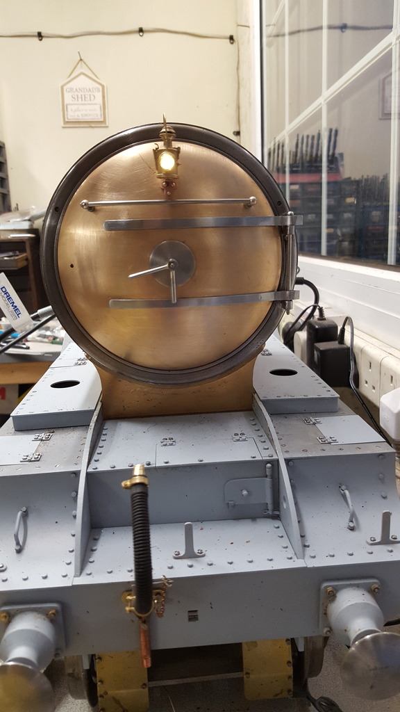
This picture shows the lamp iron riveted to the door and the door handrail fitted although not tightened up yet, I had to counter bore the rear of the door to get the 7 BA nuts to reach the handrail knob threads. Once painted I will return to the handrail and solder the parts together and round of the ends so that they are enclosed as per prototype.
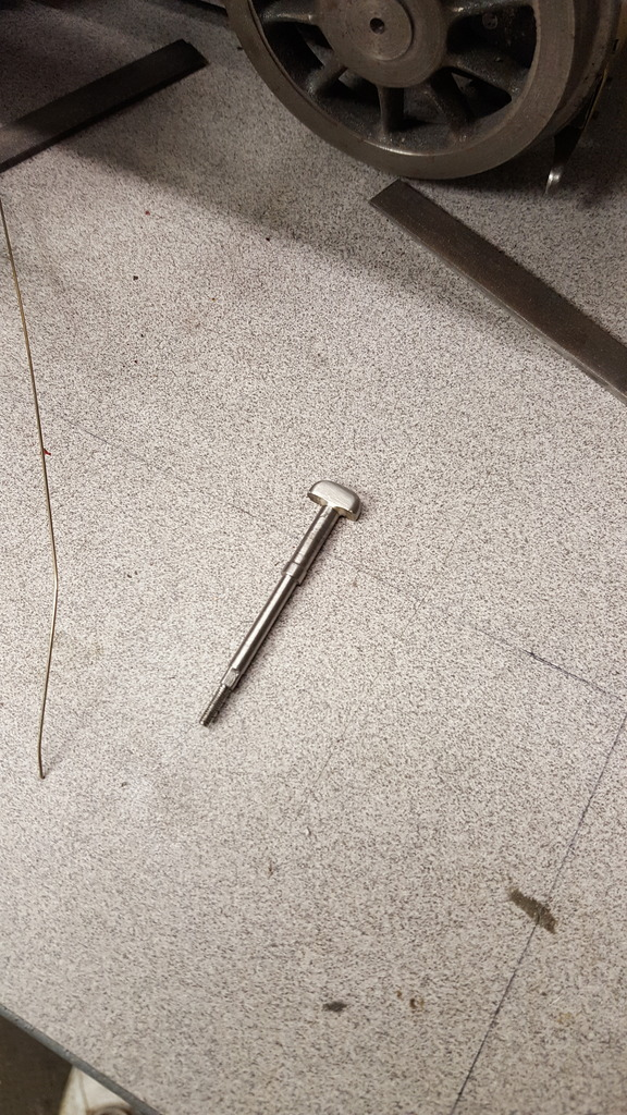
Next, I tackled the dart itself, I did this in two parts as it's in stainless and I didn't fancy machining the whole thing from solid, first part was the stem itself which involves a 7 BA thread at the tip, a 3/16 long square section and then a longer than drawing 9/64 section that goes through the centre boss, I have extended this due to the bush as it was increased in length to give me a mounting point for the dust shield to be fabricated later. Then a short 3/16 bush and then narrowed again to fit through the crosspiece. The tongue itself is a piece of 7/32 square stainless that has been drilled ready to be silver soldered to the stem, once that's done the tongue was shaped to size.
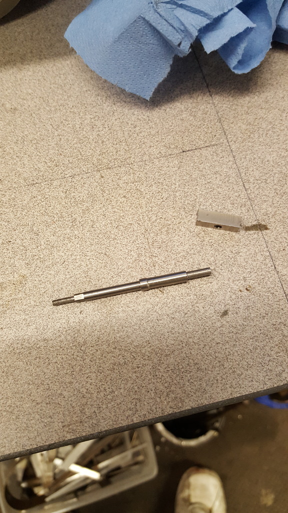
The finished dart......
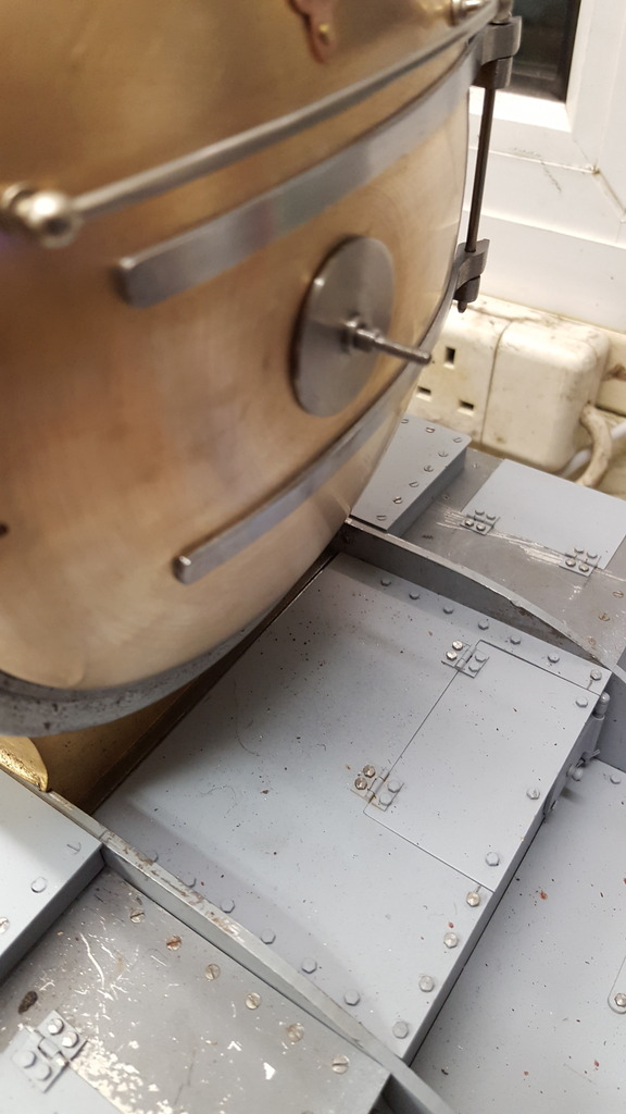
Finally, a close up to show the dart in position with the square section sitting in it's correct position...
For the handles, the screw type is a 5/32 length of 7/32 bar that is drilled and tapped 7 BA, it then has a length of 3/32 bar that is 1 1/16 long from the boss centre, this is angled forward by 5 degree's. Alas, i forgot to take a photo of this but can show the other handle before silver soldering the two parts together. In this case, it consists of a 3/16 length of 1/4 stainless that is drilled and then has the hole squared to 7/64 to match the dart. The handle bar is 7/8 long from boss centre, 1/8 diameter and in this case central to the boss, both bars are rounded off on their ends. For the square centre hole, I used a square section screwdriver insert bit that was filed down to the size required and tapped it through the hole while still in the chuck and then parted off to size.
Picture shows the inner handle (square hole) checked for fit before silver soldering.
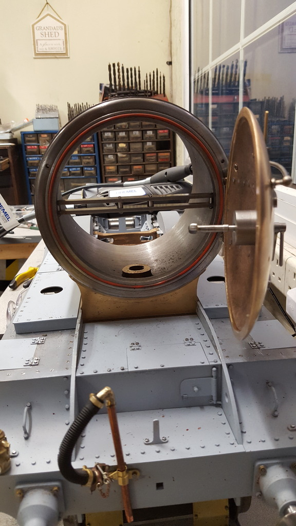
A view with the door open, showing the dart in position and also the door seal temporary fitted into it's groove to check that all tightens up properly.
Here we have the door closed showing the handles in their normal closed position, having said that I have many photos where the position varies a little but think this is the most seen position. This seems to go against what I thought was normal practice, that being that the outer screwed handle would be higher than it's downward stroke so that it couldn't work loose via gravity? perhaps I misunderstood this??
One picture for fun... clearly 4472 must be off express duty today and running a local passenger service...
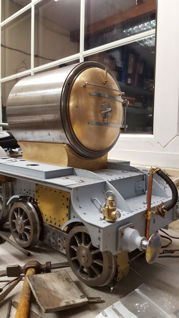
Last two photo's, first of the model at an angle to get a better view of how things are progressing....
Lastly the full size, not quite the same angle but close enough...
Jobs left to do on the door are the door knob and the ash shield, I also need to fit the two handrail knobs to the door ring, I guess after that i'm going to have to start taking things apart to look at finishing the saddle as far as I can without the centre cylinder fitted, with that done I best get the various holes for the smokebox tube plotted and cut.