

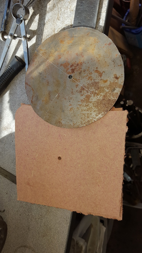
Next was to make a start on the ash shield, again something that I'd added to the model to follow the prototype. I am using some 1 mm steel here as it looks right and was what I had in stock. Picture shows the steel cut out roughly oversize using a jigsaw and two pieces of 6 mm MDF to hold the steel sheet between, the centre hole is IIRC 0.196 for the dart stem to pass through.
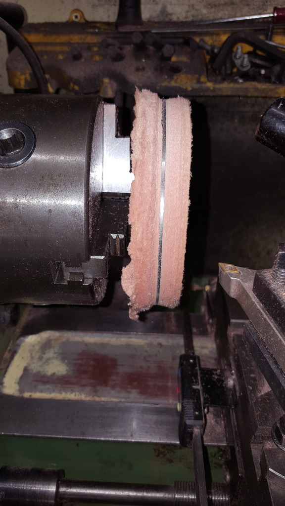
Onto the lathe then for turning down to just under 5" which is the door ring ID, the parts are held with a single 2 BA bolt with star washer and two nuts, it's the nut's which are held in the chuck allowing the bolt to be fully tightened. A pair of calibers was set to 4.996 and used to check the size during machining, remembering to measure the steel and not the MDF for obvious reasons..
Picture shows steel machined to finished size.
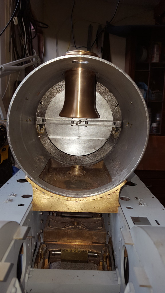
Before forming the shield a quick check in the smokebox to see that it fits..
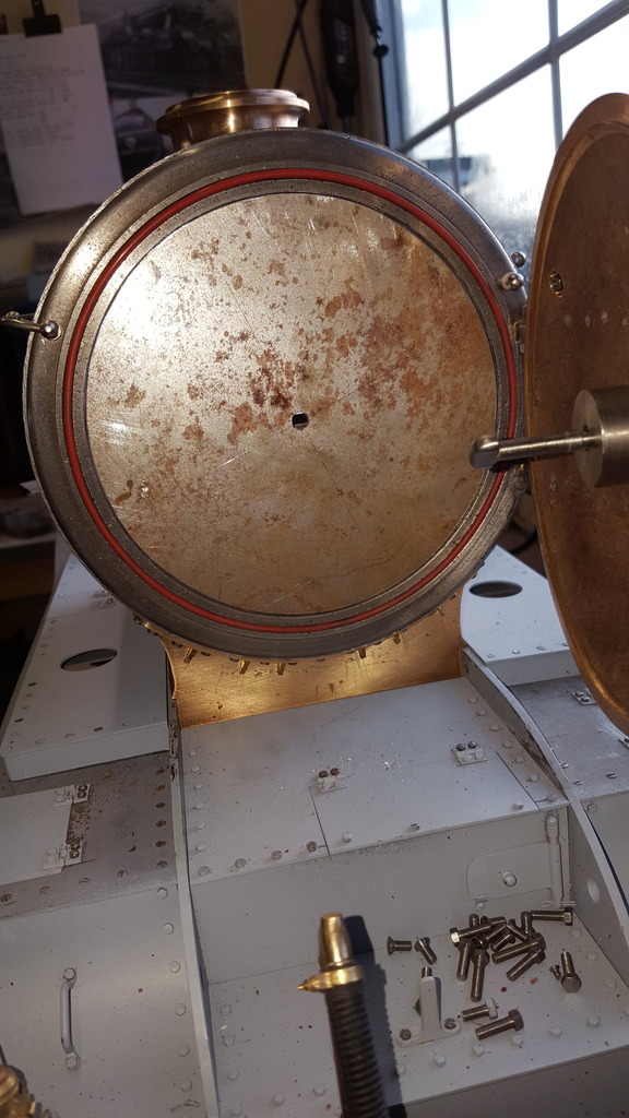
Now on the prototype, this shield is made up of two sections, it's easier to just fold the shield to shape which guarantee's a good fit, later I will dress this fold so that it looks like two pieces. The shield is hanging a little here as it's only held loosely by the dart stem but when finished it will be secured to the door boss centre as per prototype.
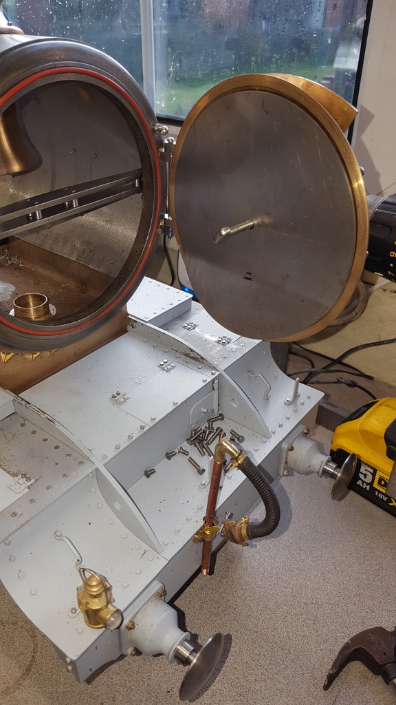
This picture is to show how the shield fits when viewed from the rear of the smokebox, it's not clear in the photo but the bottom of the shield clears the door ring back edge so that it works as intended.
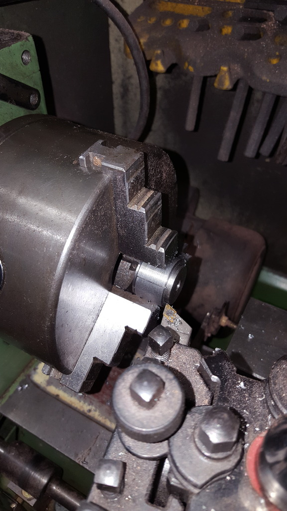
A couple of more details for the smokebox, the first job was to finish the door baffle/ash shield, I first needed to reduce the depth of the centre boss , you may remember that I had left this over length until reaching this point, with the shield held against the inside of the door I could now work out how much metal needed removing. The picture shows the boss being held in a split bush that I needed to turn up first so that I could hold it safely in the 3 jaw due to the lip on the outside of the boss. The bush was made to be the correct depth required leaving just the metal that needed removing protruding through it.
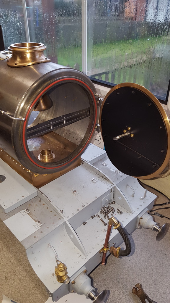
I have a few pictures missing, both simple tasks, though, one for drilling and tapping the centre boss and another showing the holes being drilled for the 12 8 BA nuts and bolts that secure the shield to the door on the prototype. I had thought that the shield was also secured to the boss but on looking more closely at my reference photos it's clear that this was not the case. I didn't want to go to all the trouble involved by fitted studs to the inner door and thus have secured it only by the centre and placing the 12 dummy bolts to match full size. It's currently being held temporarily by some hex head bolts but in due course (when I have the stock), these will be replaced with csk screws, the holes have already been countersunk. I have painted the shield in BBQ paint, alas I dropped it before it had cured so it will need sanding down and repainting, this can wait until I paint the frames, there's no rush.
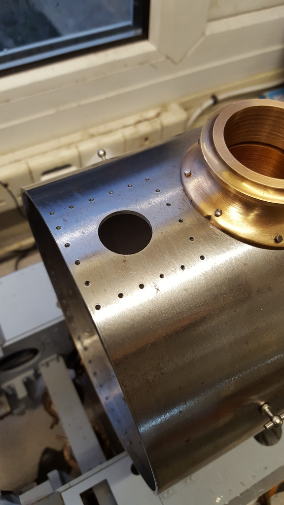
I then moved on to the anti-vacuum valve cover plate and after studying what pictures I could find, came to a size and the number of fixing bolts required, the picture shows the smokebox tube having been drilled and tapped 10BA ready for the cover. Something to note here is that after this picture was taken I repaired the casting defect that can be seen on the chimney flange with soft solder and took the thickness of the flange down a little more, this can be seen in a later picture.
And the cover now fabricated and fitted...
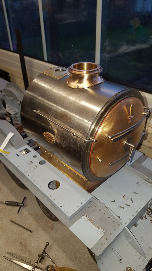
Lastly, as per usual a general view of how things are looking which shows the anti-vacuum valve cover and chimney flange after it's repair and some reworking to the shape.
NB: This was a thank you to Chris Vine, a name most will recognise for his help re the most likely chimney flange size.
'A word of thank's to Chris for his information re the prototype's likely chimney flange thickness of approx 1/2" .. having been kindly armed with this info I spent time today whittling down the flange to just under 0.050 thou and finishing off with a sharp edge. This has taken me many hours and let's just say that my fingers are now very sore, I did this using a selection of hand files and sanding sponges, hence why it took so long but I have to say that it looks much better.
I may revisit this again once I have some more sponges as mine are now dead and my fingers couldn't take any more abuse, still, I do like the result so far...
A little more progress with the smokebox details, this time it involves the superheater oval cover panels....well I searched high and low for a size for these covers, couldn't find any info in either RCTS or Yeadon's tome's and when looking at photo's they seemed to not only vary in size but also in how many bolts held them? What's more, things seemed to change on the same locomotive and not only with the oval panels? the anti-vacuum panel varied too, I was about to make another wider cover having found a top view of a pacific showing the cover being wider than the chimney flange, but after digging through images of 4472 it was clear that during her working life things changed greatly. From new there was no cover, in the twenties the cover was wider than the chimney flange, the photo that I have been using as I know it's the right era (1938-1943)it's difficult to see, the cover certainly isn't wider than the chimney, it's not easy to see due to the angle but it's either the same width as the chimney or smaller as I have done. Move on to when she's an A3 and it's smaller still and then today we are back to no cover as originally built...now there's a story...
So, for now, I am leaving as I originally made, if I find a good picture looking down on 4472 that shows otherwise I can always make amends.
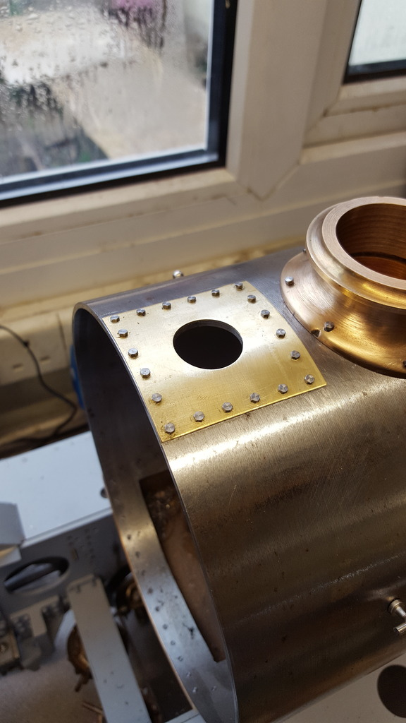
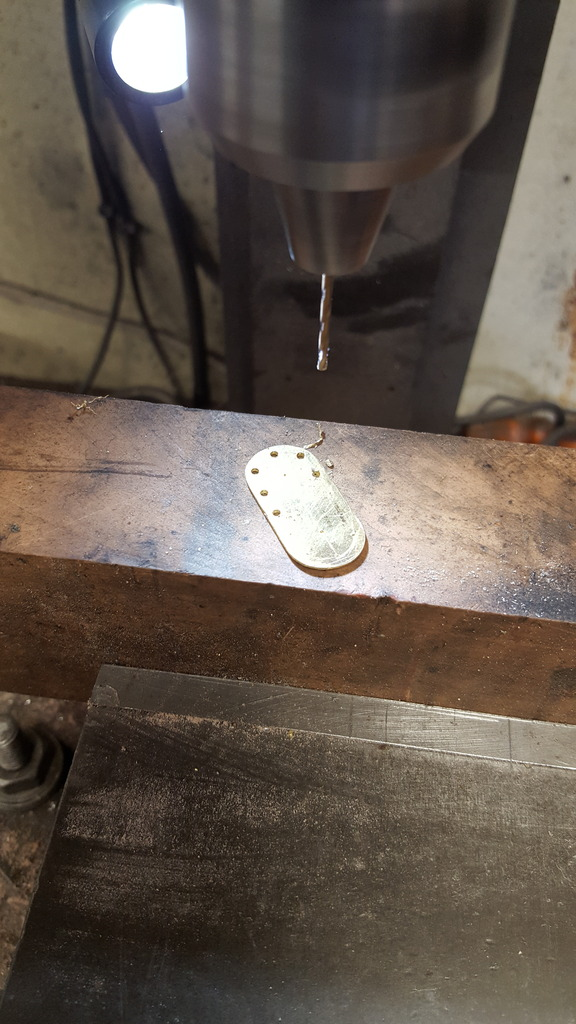
So, on to the pictures, after looking at the pictures I settled on a size of 30 x 15 mm, I ascribed this out on some brass sheet, cut and filed to shape, I had already ascribed centre lines and now added a line around the circumference to mark the hole centres, final job was to divide the area for equally spaced holes. First picture shows the holes being drilled manually, having first, center punched the marks. Due to the toughness of the smokebox tube (I'm sure it's stainless) I drilled the holes at 1.5 mm to make tapping for 10 BA much easier, these will all be sealed anyway.
Here we have the two covers ready for fitting, I do this by plotting where the middle hole needs to go for the top edge, I drill and tap this and then bolt the cover in place and squaring it with the smokebox tube. I then do the same for the lower middle bolt, tighten the cover and after checking that it's still square I mark the remaining holes for the same treatment. I should add that I don't open out any of the holes for clearance of the bolts to fit until each hole centre has been marked...it takes some time but keeps the holes in the right positions......hope that makes sense??
I tried to take a picture square on from above to show that the panels are equally spaced but failed to get the camera on the correct position, it's close enough, though....
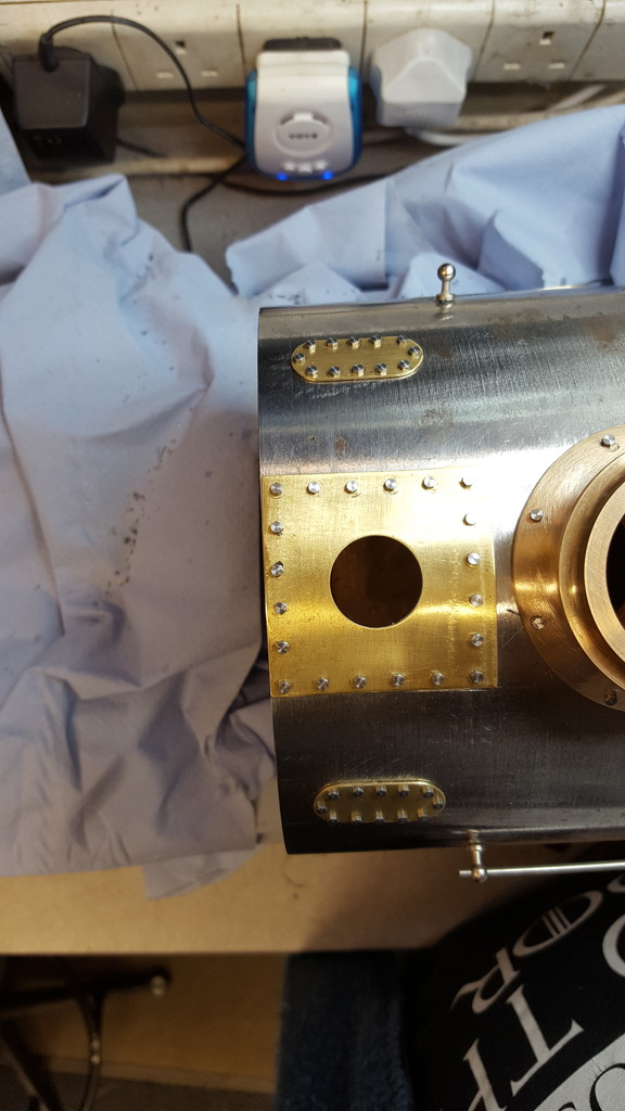
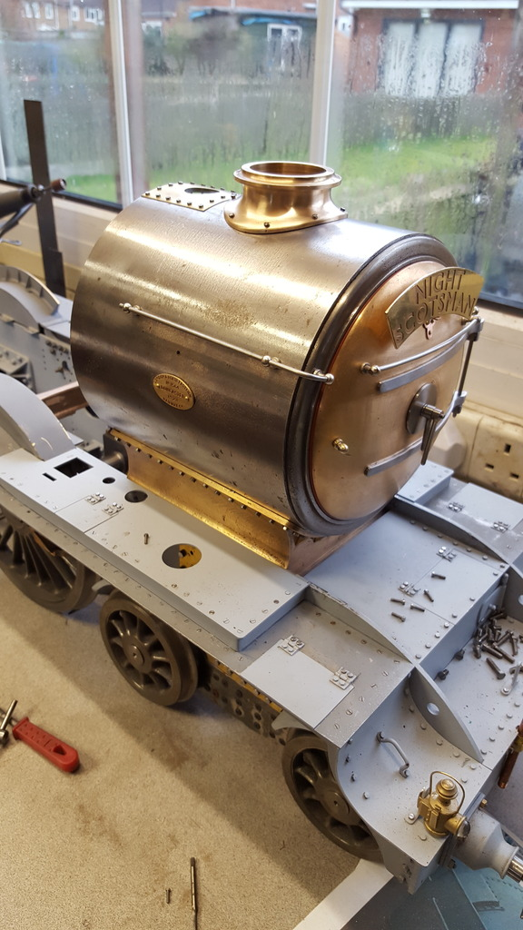
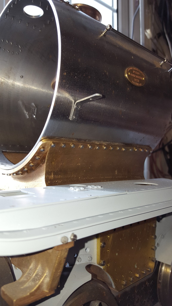
Last picture to show how she looks, the first square on....
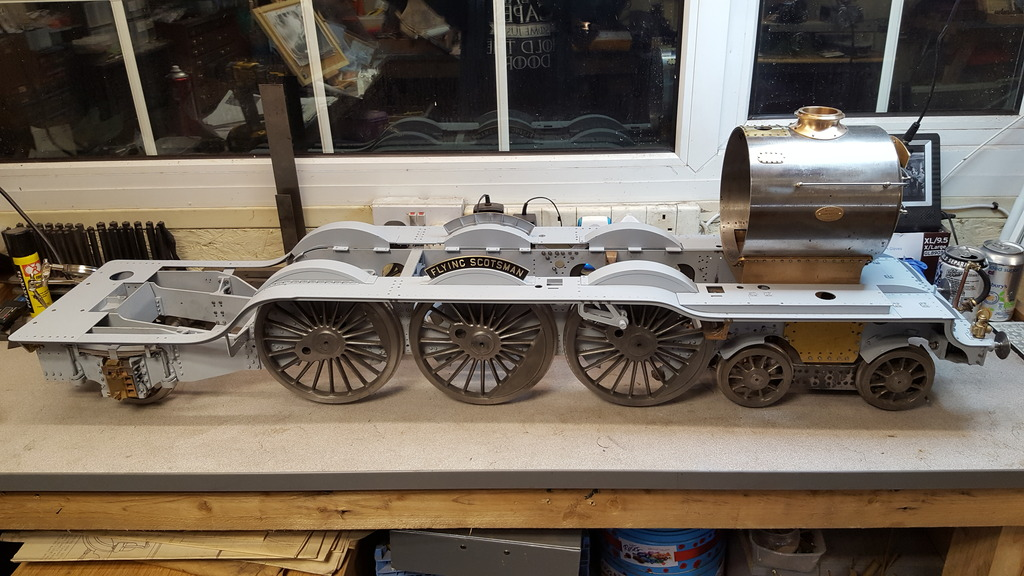
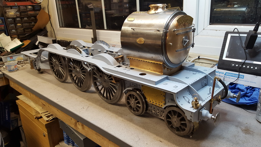
And so, the usual picture showing her quarter on which is how most of my reference photo's are, so helps me see if things are looking ok? a few things to point out here, the most obvious being that she has a fresh coat of paint on the running boards and parts of the chassis, it's a lot of time removing all of the running boards I can tell you. Of course, there are the oval covers which when comparing with photo's I'm pretty happy with. If I haven't mentioned it before (can't remember) the vacuum hose has been trimmed very slightly giving a much more realistic shape and lastly, I have finally got around to reworking the buffer stocks to remove that sharp edge which was wrong.
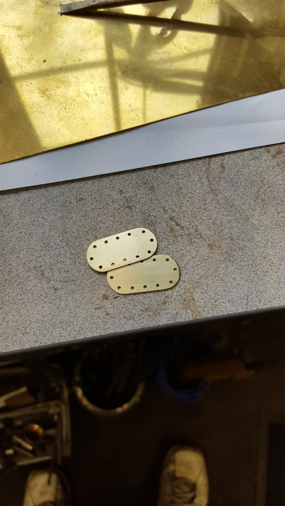
Just to move on from this as I'm going in a different direction next, here's a picture for which I wouldn't expect anyone to know what they are. This steel was machined down to 6 mm wide, marked out and drilled, these are not cut to length yet here.
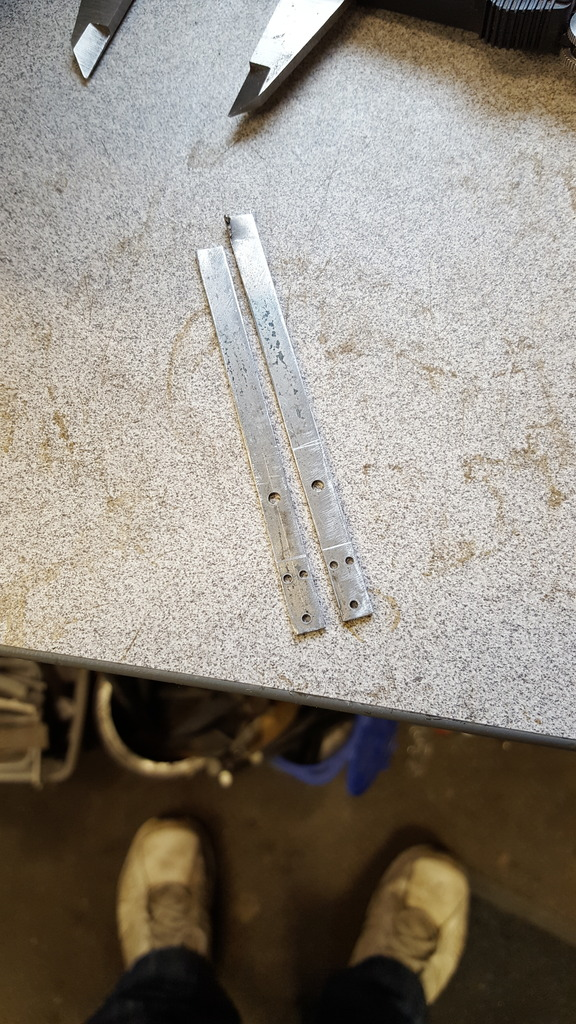
I have two pictures from different angles... first, from below, Don did give drawings for these, I have changed them a little by having 3 mounting bolts as per prototype rather than the single bolt that Don had drawn. One thing that I haven't done yet, the brackets today have a slot through the centre, not sure of the purpose for this or if it's a preserved days addition so will need to look further into that.
and a picture from above, their purpose?, these (one either side) are the mounting brackets for the oil atomiser units, I will build these in some detail later but they will, of course, be dummies, unless that is ,anyone has built working items to scale before, I doubt it's possible but hey if someone has please speak up...

As for taking a different direction, I was re-reading through Don's notes and came across a reference to a drawing for the front steps, I hadn't realised that Don had drawn these up. After searching through the drawings I found the steps on the very last sheet which is mostly consigned to additions, double chimney/blast pipes etc so no surprise that I hadn't spotted it previously. I took a lot of photo's of these steps when visiting York last year and it's nice to see that Don has drawn these up very detailed as I've come to expect. I do need to just check the depth of the steps as I recall noting that at some point these had been reduced in depth from how they were in my chosen era.
So next update should be on the steps, both front buffer and cab steps, lot's of drilling/riveting....again.