Next up was the steps, both front steps and cab. I made a start on the steps beginning with the front brackets that are fitted to the bottom of the spring housings. I've used some 1.2 mm steel that was in the off-cuts box, it's not pretty but will be fine once finished and given a coat of paint. Each bracket has a triangular stay for support which is riveted in place, I thought that the two mounting holes would be a good way of holding the two brackets back to back for final shaping. That was the plan and I duly marked and drilled the two holes down the center line of the 1" wide steel, totally forgetting that there's a recessed section and the holes need to be in the middle of that, not the wider 1" that forms the top return tab...lol such is life, anyway I carried on and used the holes for 1/16th rivets and machined the recess. I will fill these with silver solder later when I solder on the steps themselves.
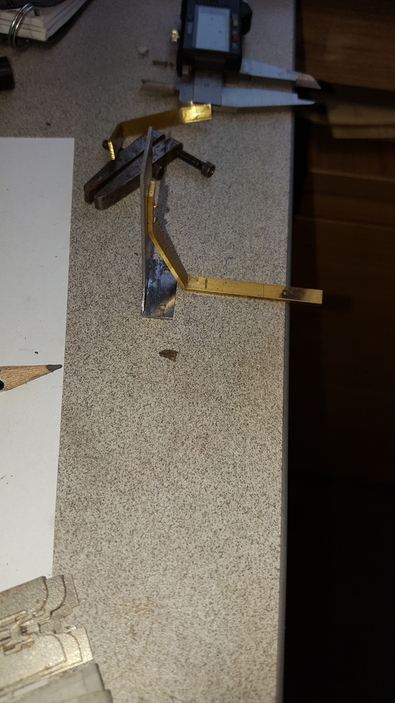
having remarked/drilled the holes in the correct position, I folded the return tabs and checked that both mirrored each other correctly.
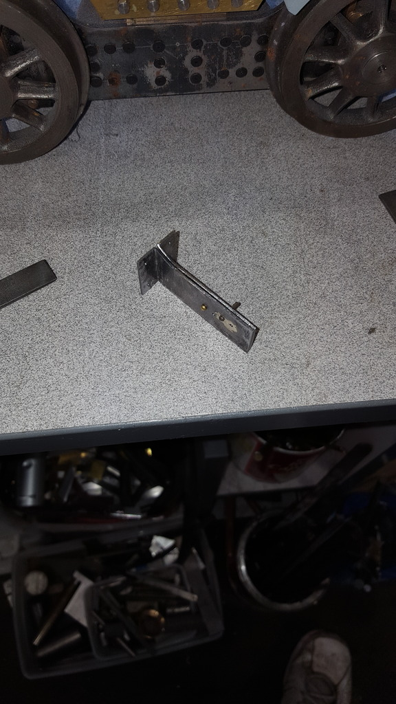
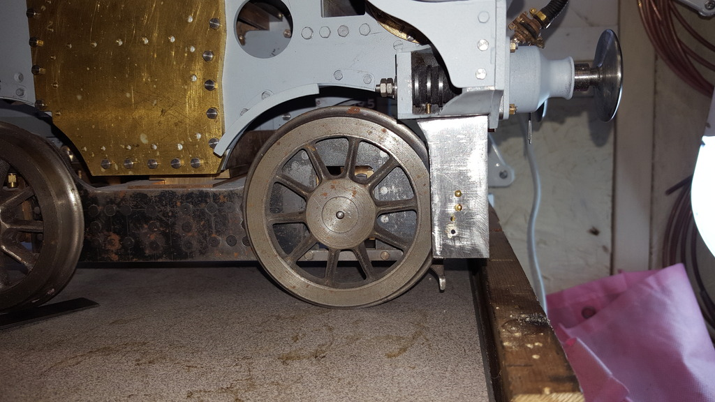
Next job was to form the triangular supports and rivet them to the back of the steps checking that they stood up squarely...the support as seen here still needs cutting to length.
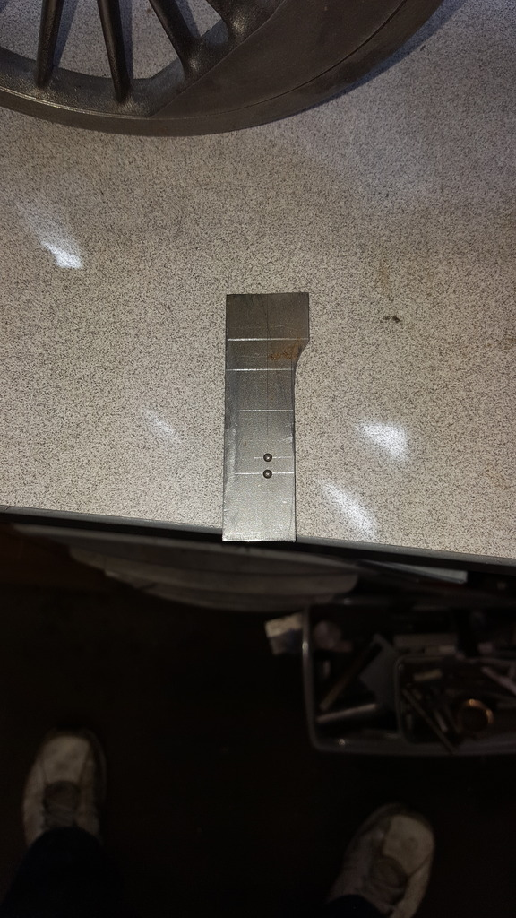
A picture to show the profile of the bracket, it looks crooked at the top but it's just a trick of the camera, it is vertical on both axis. you can see the holes that need filling, oh and I accidentally damaged on of the rivet heads so will need to sort that out in due course.
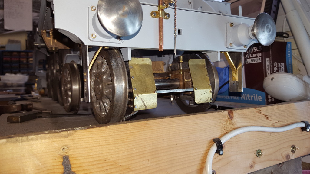
A view from the front to show the triangular support brackets, I have used 8 BA bolts for extra strength in holding these. The wide angle lens on my phone when too close to the subject makes everything look crooked, even the buffers look off, I did double check and promise that this is not the case.....
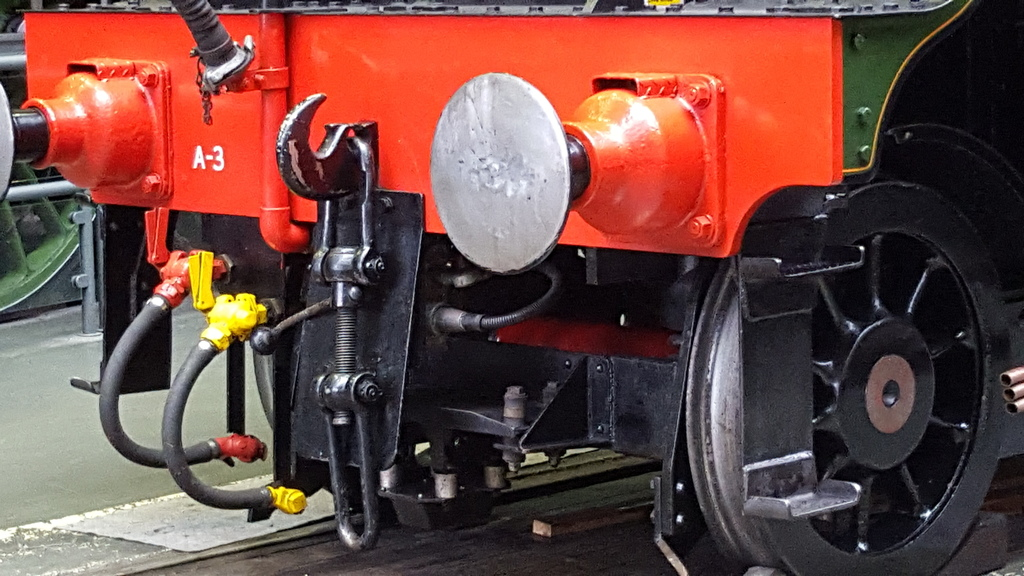
The final picture for tonight is to show what the full size looks like, I took this picture of Flying Scotsman in April 2016 when I visited York NRM, actually, I took a few hundred photo's all being put to good use.. This particular picture is a good example of how things change during a locomotive's career. The buffer steps we have already covered, then there's the platform added to the front of the bogie for the (IIRC) AWS gear. The screw coupling shield isn't original, nor are the air brake hoses. Most of what's seen in the middle of the picture is foreign to 4472 as she was in her LNER days. Note the two different buffer pattern stocks too.
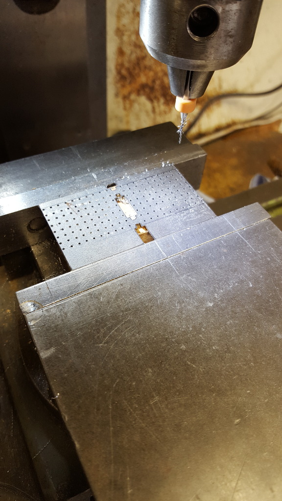
Ok so the first job was to drill the holes for the 1/32 rivets, the rear steps were drawn up in CAD for me by John (baggo) and then laser cut by Malcolm, so they are easy enough. At the time I wasn't aware of any front steps fitted during my chosen era, however, further research has now shown that 4472 did have her front steps refitted although of a different type to the original ladder shape, so these have been fabricated the traditional way with a little hacking and filing. First picture shows the upper rear steps (slightly smaller than the lower) held in the machine vice having had the required 0.8 mm holes drilled using a carbide PCB drill bit. For this job I have left the steps on their tabs as pairs to make life a little easier, each of these particular steps has 80 holes at 3 mm pitch.
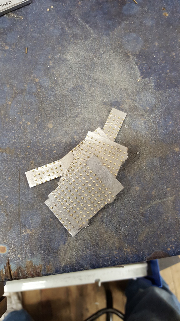
Moving on a little, here are all 8 steps with their rivets fitted, this involved 472 x 0.8 mm holes drilled, turned over, CSK and then of course hammered in place...
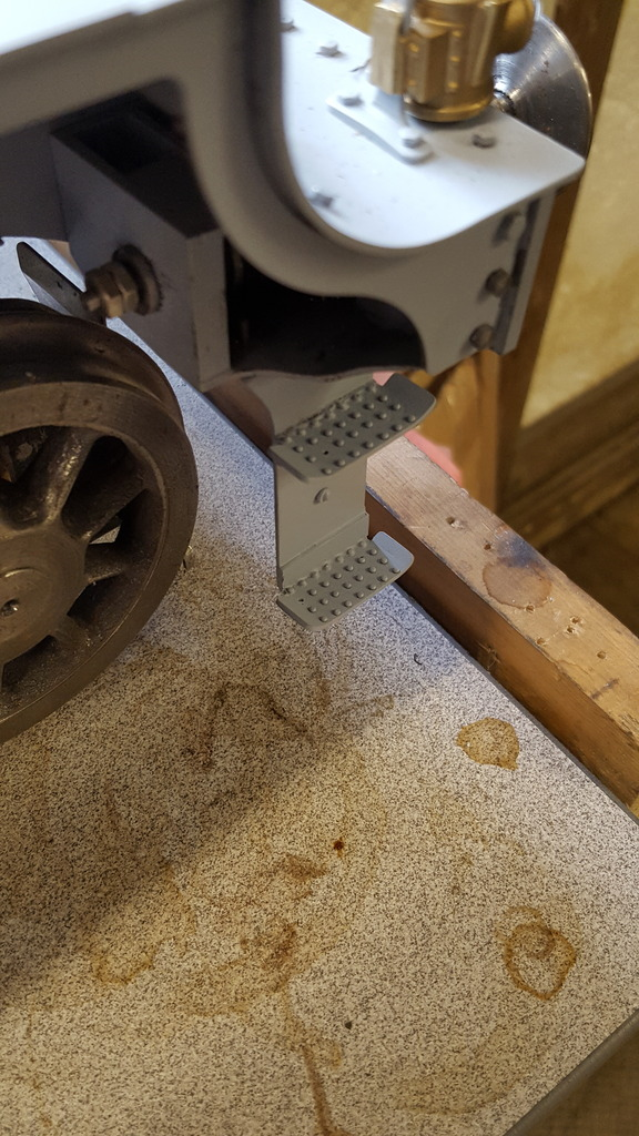
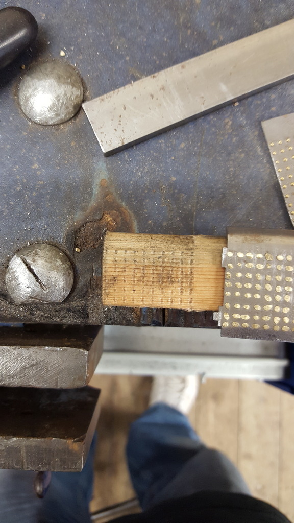
I then needed to form the steps into shape, this seems to have varied over the years, today the steps have large raised sections either end but back in the day they were curved at the front and angled up at the back, or at least that's what the photo's suggest. Now when I did the buffer housing with their joggled shapes I made up an elaborate jig but for these I had a much simpler idea to get them all the same. This involved a piece of wood with a curved edge and some flat steel to squeeze the steps between. Once happy with the position I dolly hammered the metal to form the curve, the rear angle was just a matter of clamping in the vice and tapping with the hammer. The picture hopefully shows how I got all of the steps to have the curve in the same place, it was a simple job of lining up each one in the depressions left from the rivets heads of the first step formed, worked a treat and so much quicker.
Next job was to plot the 2.25 mm mounting holes for 8 BA bolts, 4 in the lower rears and 3 in the uppers, front steps are welded on the prototype today and I have used that method too, well soldered.
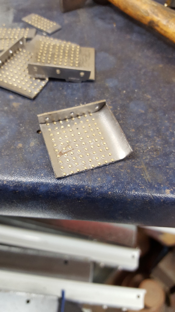
Last two pictures to show the completed items, they were silver soldered together, given a good clean, the corners were rounded off and primed. Here we have the rears....
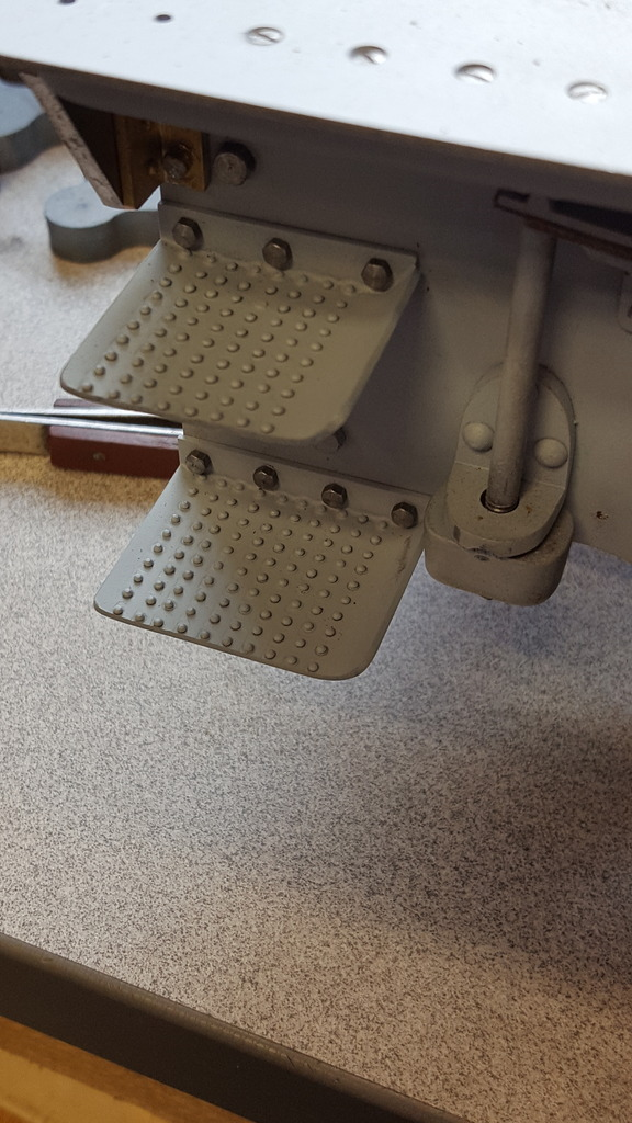
And the fronts...you may notice that I have a couple of rivets missing, this was me getting tired with the drilling and breaking a couple of bits, I've left them as is, kind of fits with the gaps that I've seen in photo's....well at least that's my excuse...