
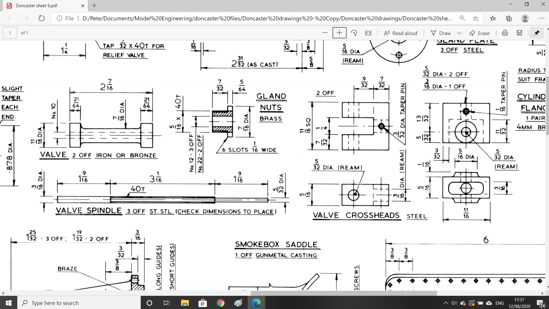
I'll begin by showing the drawings, the 'valve' (bobbin) will be redesigned, I haven't drawn this up yet, that will be the last item on this current list.
Something to note here is that both the glands and the cross-heads vary in spec. For the glands this involves 3 off with No.12 bores for 3/16 end of the spindles and 2 at No.22 for the 5/32 ends. The cross-heads come in two sizes, the larger size is for the rear guides that connects to the combination lever and the other 3 for the front to connect to the conjugated valve gear links. Things are further complicated as of these 3 cross-heads, the middle is drilled for the 3/16 spindle end while the outside cylinders is drilled for the 5/32 end. The reason for the difference is that the middle cylinder spindle is fitted in reverse to the outside cylinders, this will be explained more later. The spindles are plain turning although will require some delicate machining to achieve the narrower 5/32 end and of course, I have further complicated the matter by needing to machine up two close fitting collars to correct my error.
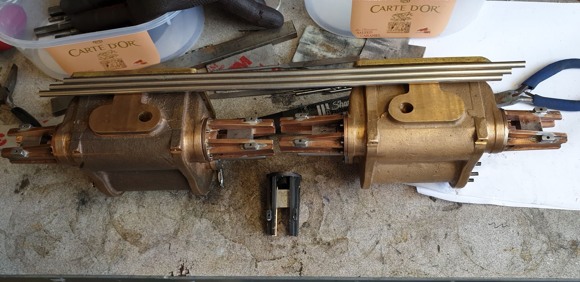
The first job was to machine the blanks ready for the cross-heads, once I was happy with them I lapped each to it's allotted valve guide to ensure smooth operating. The picture shows the blanks sitting in their respective guides, also seen is the 3/16 stainless steel bar ready for the spindles. Strangely the drawing for the spindles states (check dimensions to place)? and yet later gives a fixed dimension between the back faces of the crossheads? I can't see how these are (check to place) like the piston rods are due to the required distance between the crossheads, so I'll make them as per drawing and go from there. Interestingly Don also states to leave the taper pin holes till later too? I'll take a closer look to see why but think these can only go in one place and unless anything jumps out at me I'll drill these during the cross-head construction.

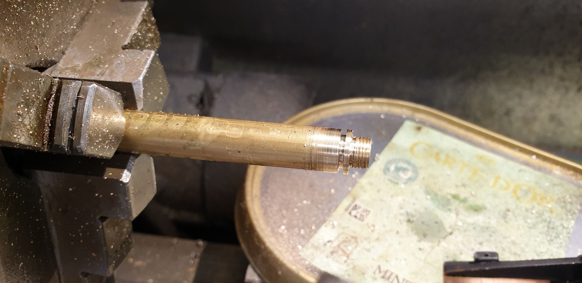
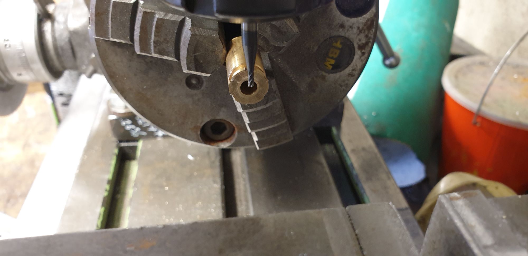
The glands begin life as 7/16 brass bar, reduced to 5/16 for the thread to fit the guides and a narrow flange that needs to be castellated. I will be fitting 'O' rings and took the time to test fit each gland before parting off. Here is one of the glands machined.
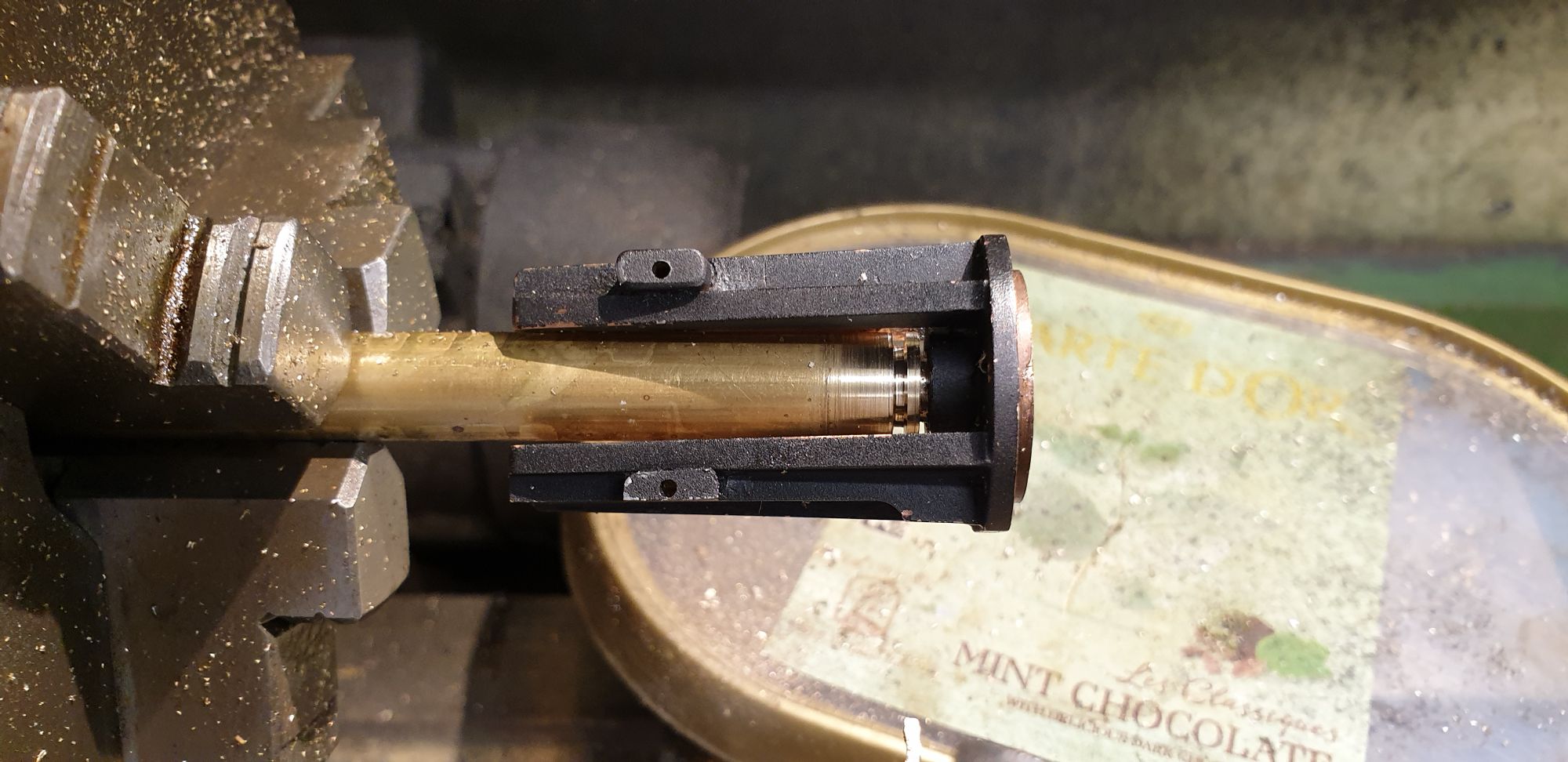
And here before parting off fully I have test fitted the valve guide to check that it screws in fully so that the gland can be accessed through the access slots and also that it isn't sitting too proud as the moving parts get fairly close here. This is the middle cylinder guide and giving this a little more thought I later slightly enlarged the castellated cut outs on this particular gland as getting to this isn't going to be easy, I'll have to make up a purpose made tool.
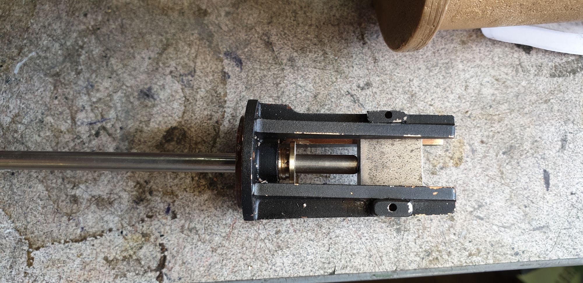
As each gland was made it was fitted to it's valve guide and checked that it was running true, here I have inserted a length of the 3/16 stainless steel to ensure that the action is smooth.
Once happy with the gland fits, each in turn had it's slots machined on the rotary table.
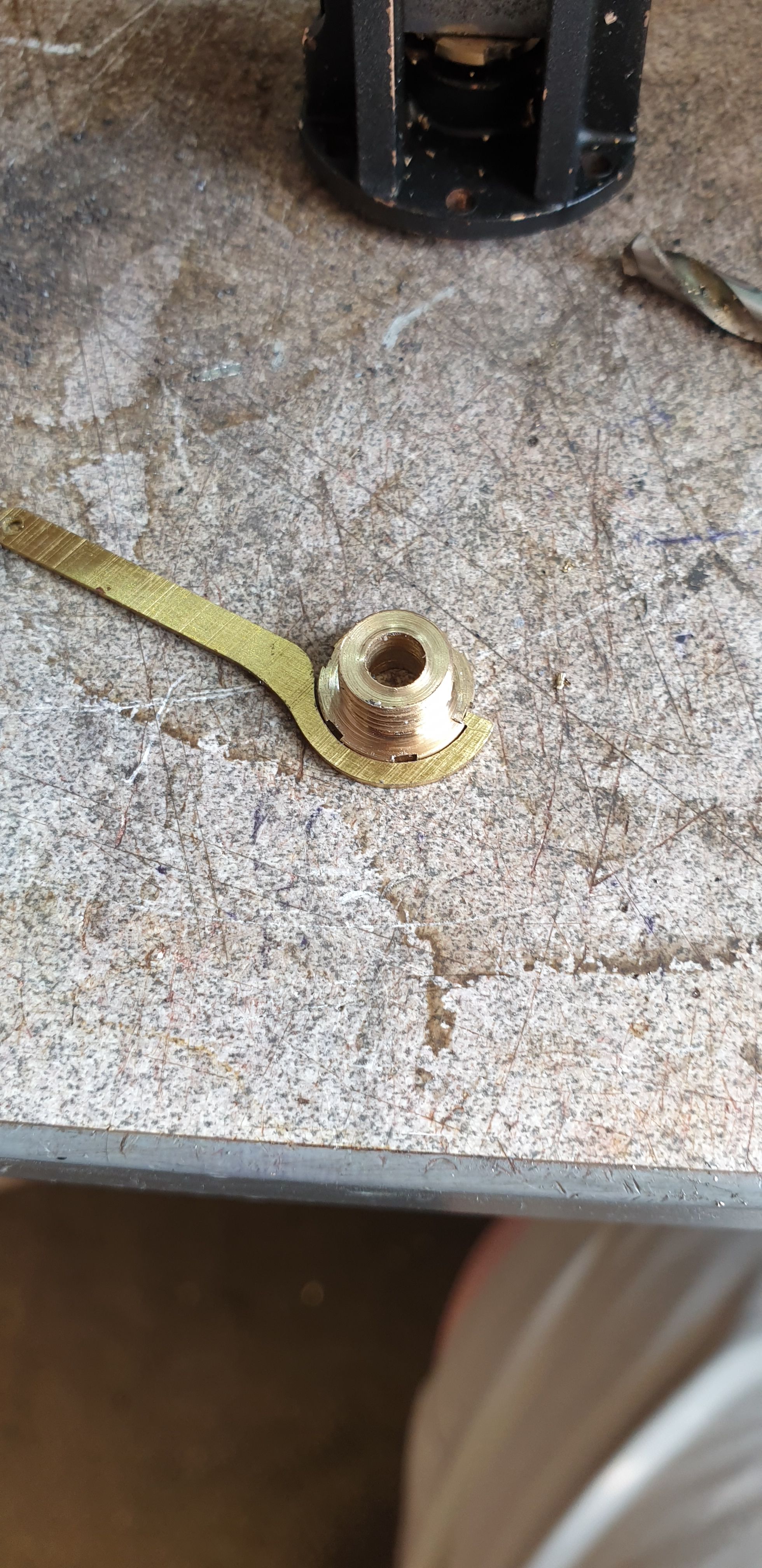
It then occurred to me that these gland nuts may be close to the castellated nut size that fits to the ejector elbow on the smokebox. Adam (Cro Fittings) had drawn up a 'C' spanner to fit these nuts for me and as luck has it this fits the glands too. As it stands, it has too thick a neck to get to the gland nuts but a little modification should sort that out. I might ask Adam for two more so that I can laminate them together to replace any strength lost from reducing the neck width, that's for another day.
In the next update I'll finish off the cross-heads and machine the spindles, after that it will be the bobbins. With those parts done the cylinders will be getting very close to being properly fitted to the frames, there's a fair bit of 'odds and sod's to do first but that day is getting closer.