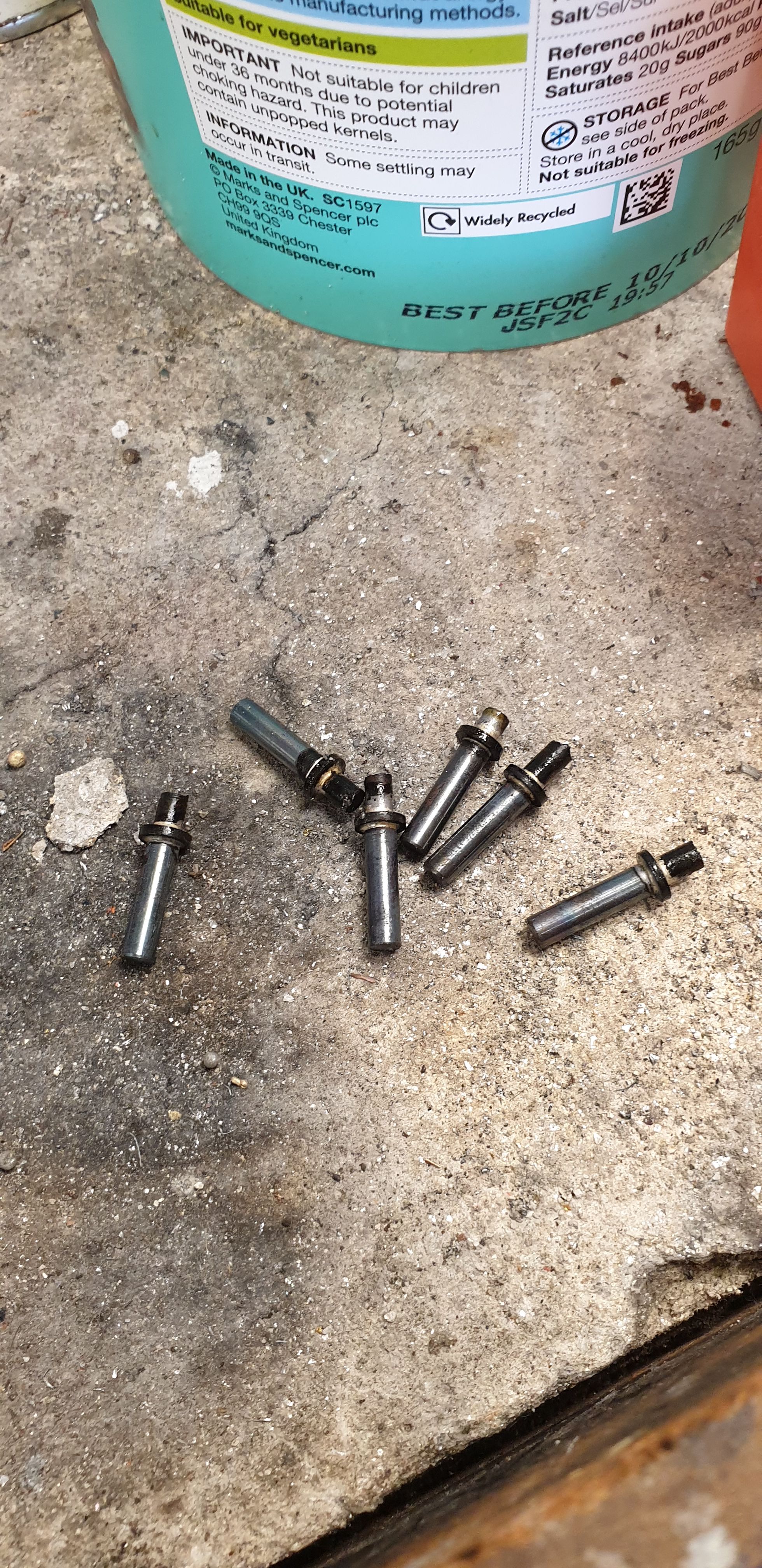
Once I had finished the bushes for the outside links I then moved on to the 6 pins, one of which is slightly longer for the 1:1 lever fulcrum. It may be that I'll need to shorten the pins for the cross heads but as those are yet to be made this will have to wait for a while, I won't cross-drill these particular pins until then.
The first picture is just to show the pins after being silver soldered together, the pins are 5/32 OD and the 1/16 tops are 1/4 OD. The pins were then centre drilled deeply to form a small reservoir for the No.60 oil ways which I'll drill later once I have a new drill for the job. They will also need a small cross drilled oilway where the bushes will meet. After this picture was taken the tops were shortened to give an overall height including the cap of 5/32 and cleaned up on the lathe.
Once the bushes had cured overnight ( I used Loctite 640 to ensure that none would move in service), they were re-reamed 5/32 to re-open the holes after being press fitted into the links.
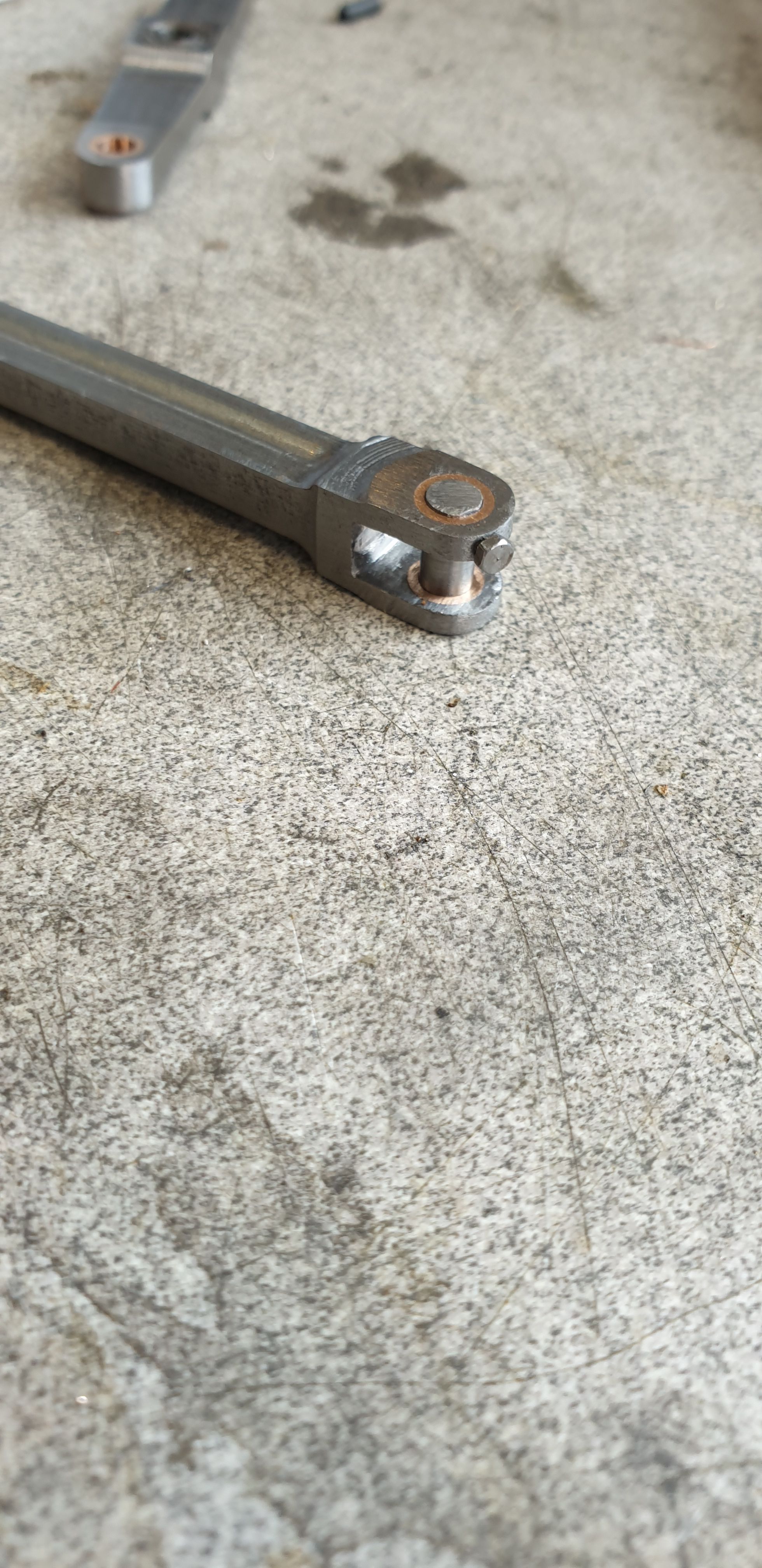
I then took a look at how i was going to secure the middle cylinder link to the 1:1 lever. Having been informed that on the full size there is a 3/8 taper pin that goes through the lower link fork and into the pin I looked at doing something similar but using a bolt instead of a taper pin. The reason for this is a taper pin over time may get stuck and with no way to tap it clear from behind, a 12 BA bolt seemed my best option. Just to note that he link in the picture is shown upside down. As added security to stop the pin from slipping down (it couldn't go anywhere as it's encapsulated within the 2:1 lever but at high speed it may just be possible for the pin to jam) I have filed a small flat area on the pin, this helps the bolt to grip and also makes it impossible for the pin to drop while the bolt is in place.
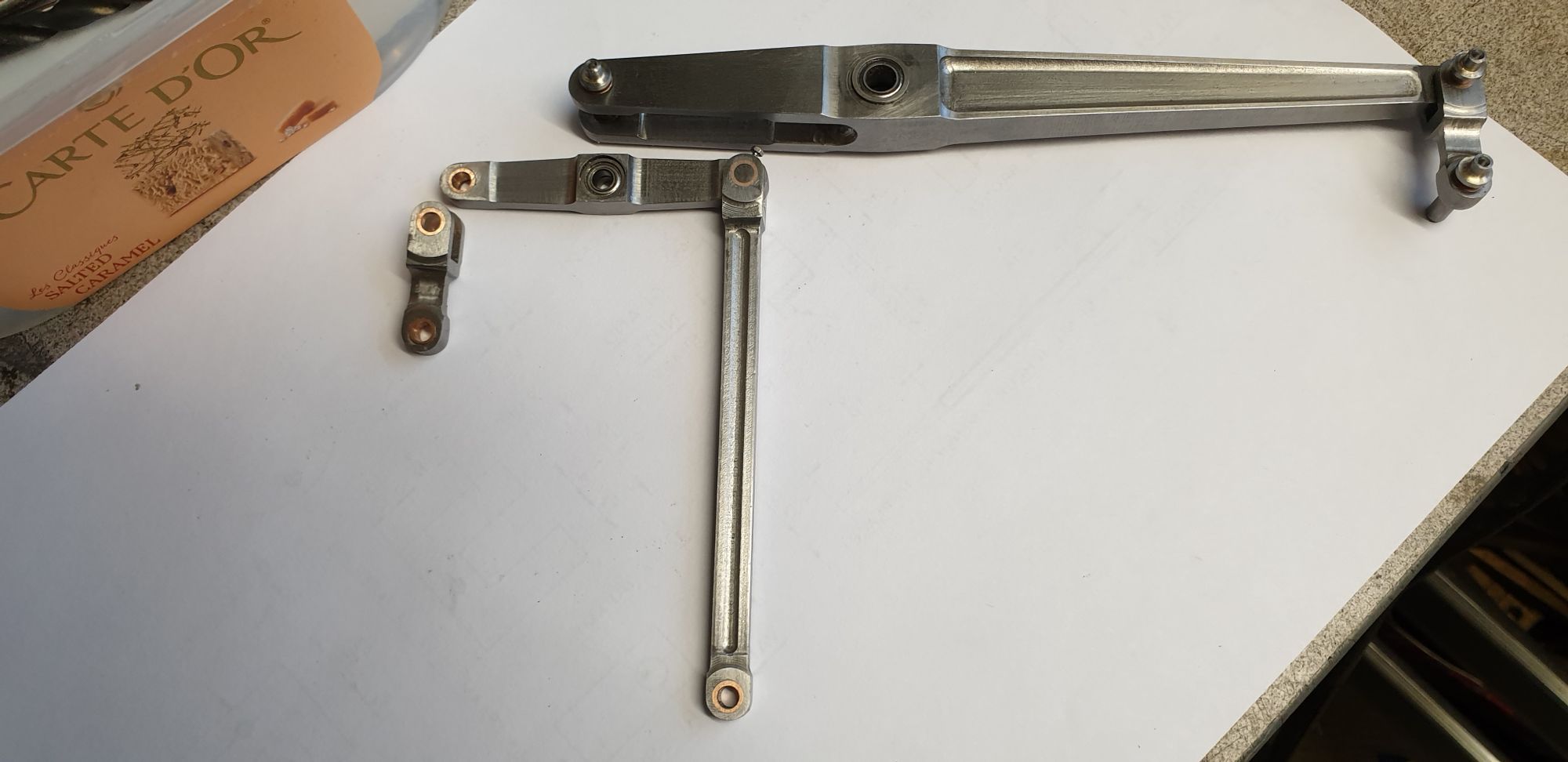
Here's the various components awaiting assembly, they are seen broken down here into sections which can be easily assembled onto the model.
A close up showing the middle link pin and bolt fitted to the 2:1 lever. looking at this picture now I note that I haven't fitted an oil nipple to the 2:1 fulcrum yet, also it's probably a good idea to do the same for the 1:1 fulcrum pin too as that has no oil-ways.
Here's the 2:1 lever assembled to the model, I have also taken a 'time-lapse' video of the unit being assembled on the model, please forgive my arm getting in the way, it was the only place that I could easily set up the camera on a stand, hope it's of interest.

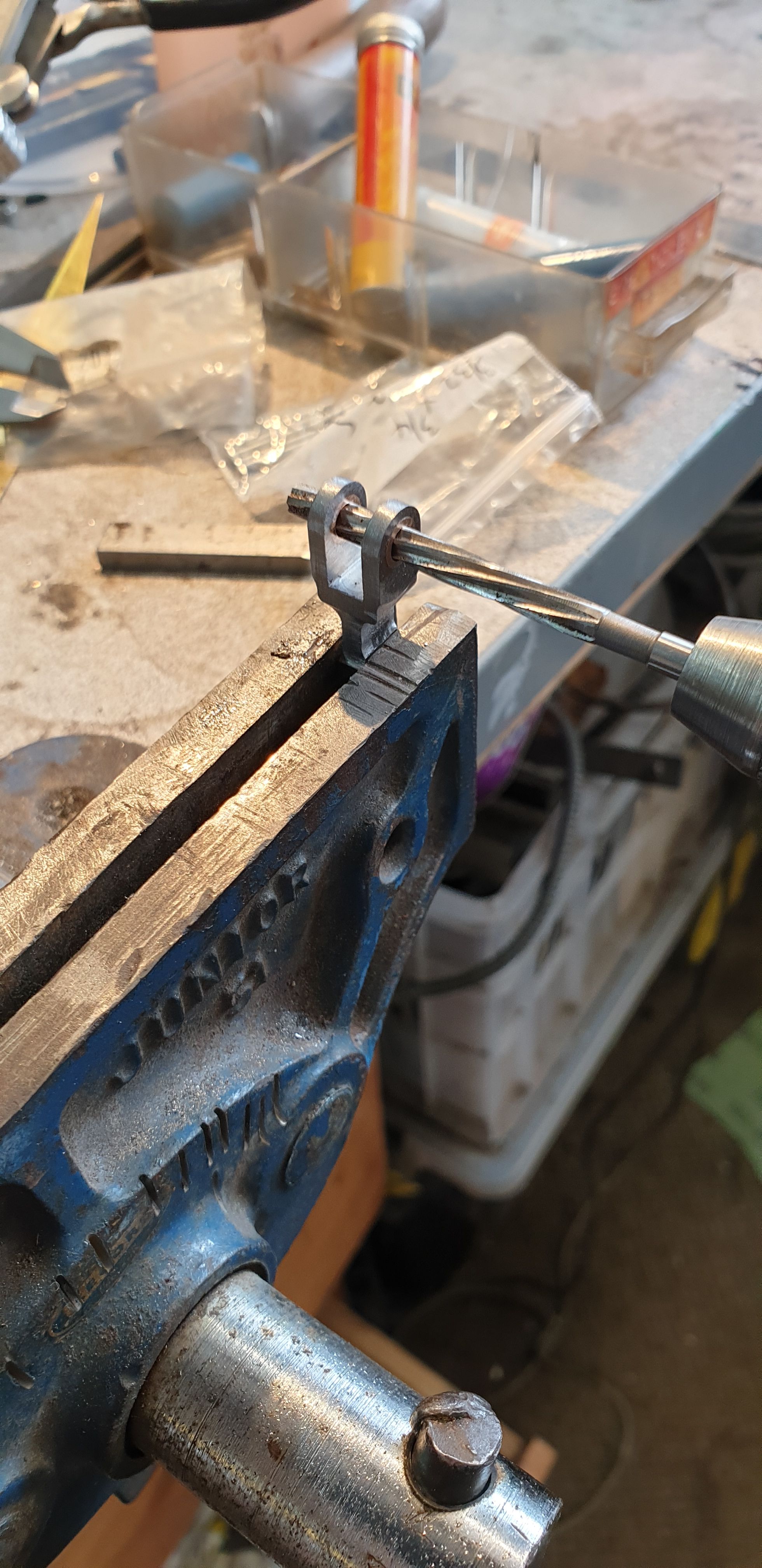
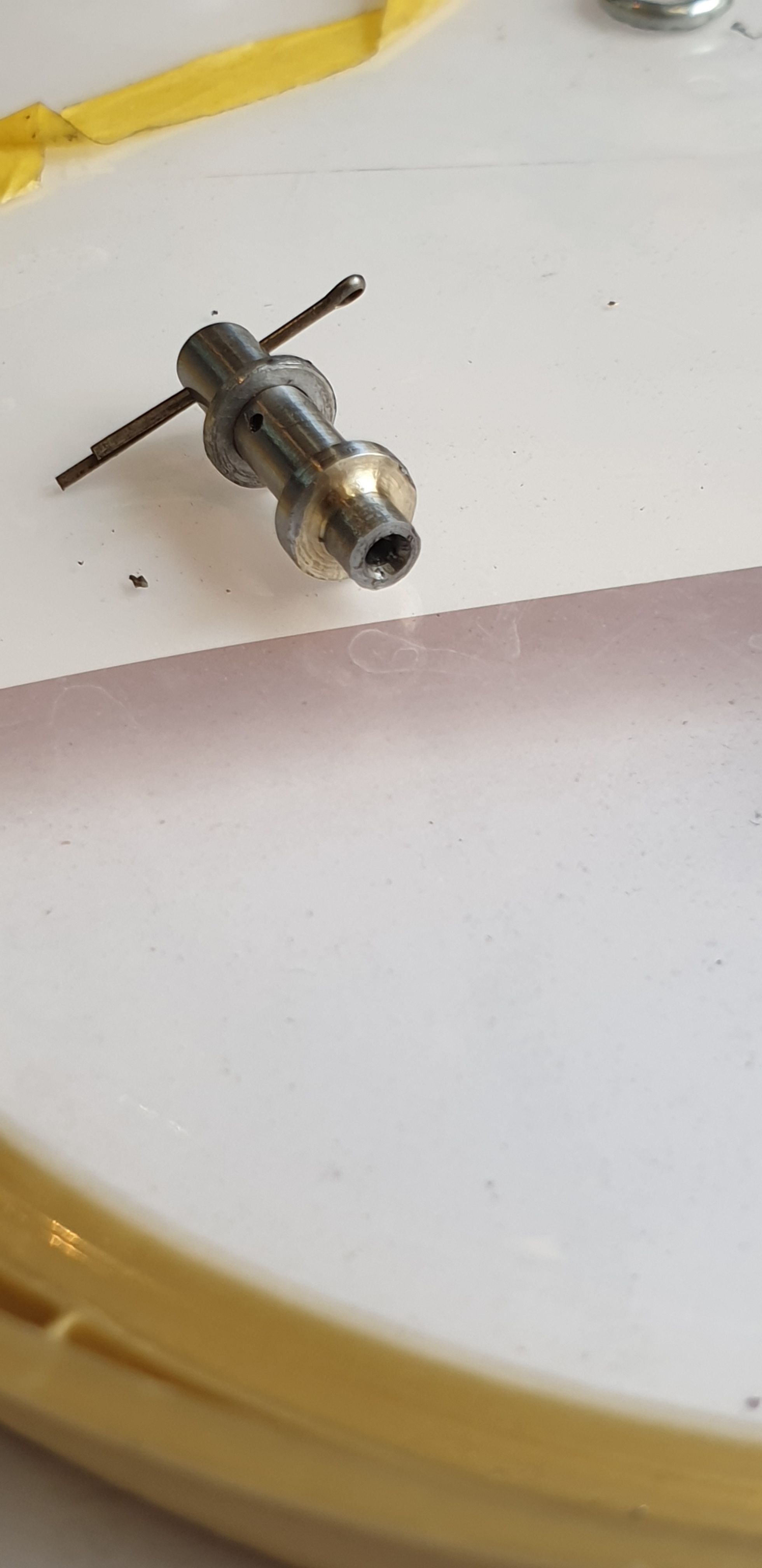
With the parts doing as they are supposed too I moved back to the oil ways in the pins. these are drilled No.60 down the middle from the top to approx half way and then cross-drilled at the level where the connecting part swivels. Once this was done I then made up the small washers and marked where the hole for the split pin needed to be. I have used 1/32 split pins rather than the 3/64 drawn by Don as they look closer to scale. The picture shows one of the pins now completed, note the the oil-way hole in the top has been angled to allow oil to get in easier and also act as a small reservoir. I'm not sure if these have cork plugs or metal caps to keep the ash/dirt out on the full size, I'll probably add something later to help here.
Going back to the 2:1 lever, I have added a brass cup to the oiling point to make it easier to engage the oiling can. This is hidden behind the 2:1 stay front wall, there may be enough room for a shaped oil pipe to get in, if not it will be a case of pulling the fulcrum pin to get to the oiling point, this is easy to do without upsetting any of the timing. Instead of oil I may pack grease into this as there are now ball bearings here as per full size.
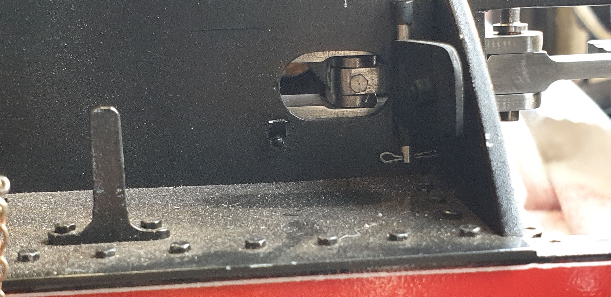
The other oiling point in this area is the middle valve connecting link, here I have drilled/tapped for a short 10 BA bolt which can easily be removed and oil put in to lubricate the bronze bush when the access door is open. The number of oiling points on this model is getting very large, think I may need to write up an oiling procedure 'check-list' to ensure that I don't forget any before each steaming. Looking at this picture reminds me that I still need to repaint all of the running boards and smokebox, I may do this in the very near future.
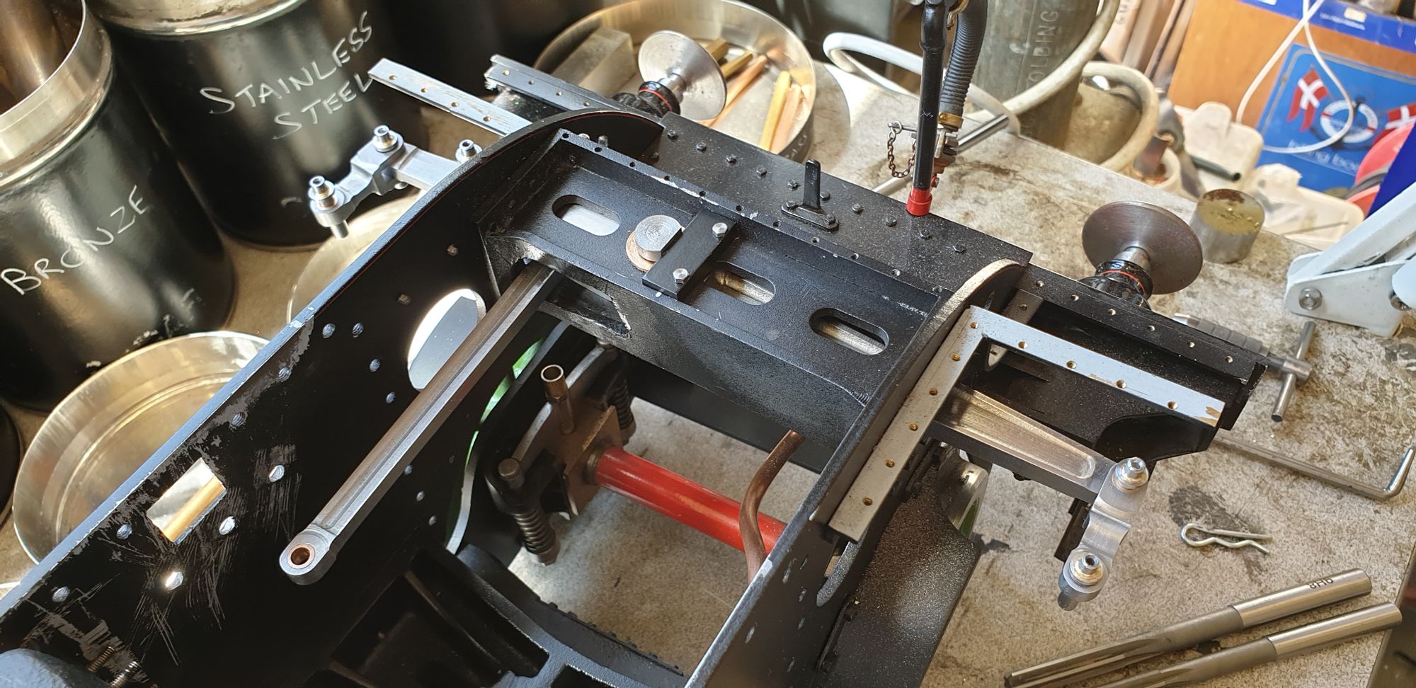
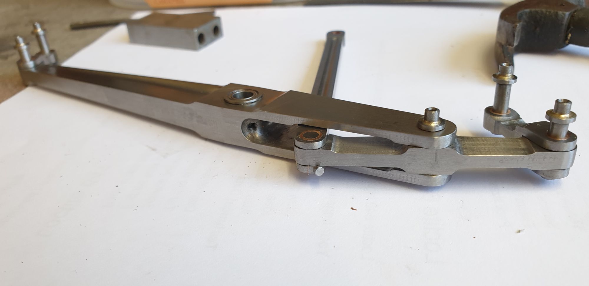
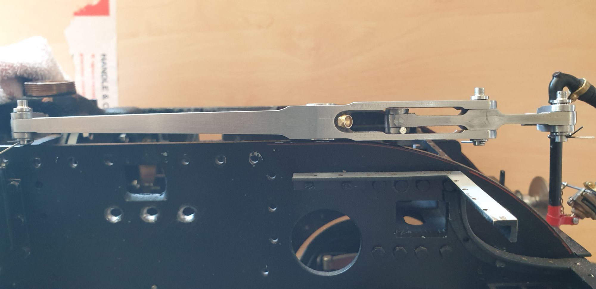
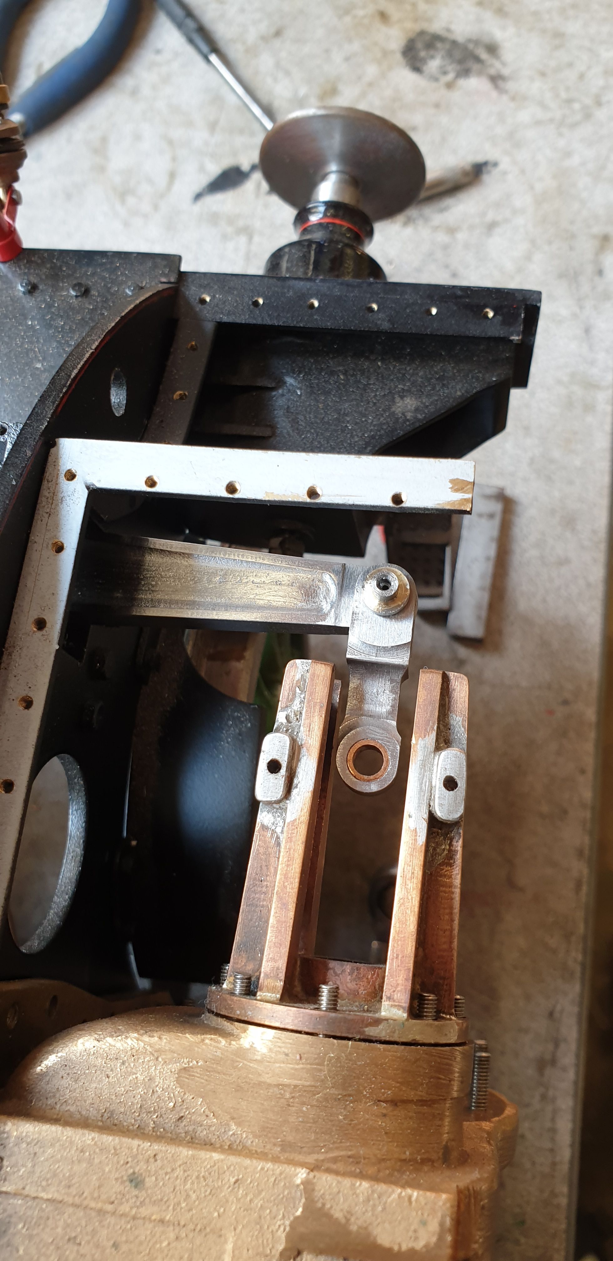
With the 2:1 gear temporarily assembled I thought it best to check if it lined up with one of the outside cylinders and its associated valve guide. I have to say that it's looking good, the cylinder is only loosely held onto the frames and the guide isn't tightened up but all in all I'm happy with the outcome. Lots of tidying up to do here too but with each new part made I'm getting closer to doing the final touches on the parts made so far. I was going to finish off the link knuckle, ie round it off, I may still do so but all of this is encapsulated within the crosshead and completely hidden, do I really need to go that far? A question for myself later, perhaps one of those little jobs that can be done after the model is finished and in steam..:)
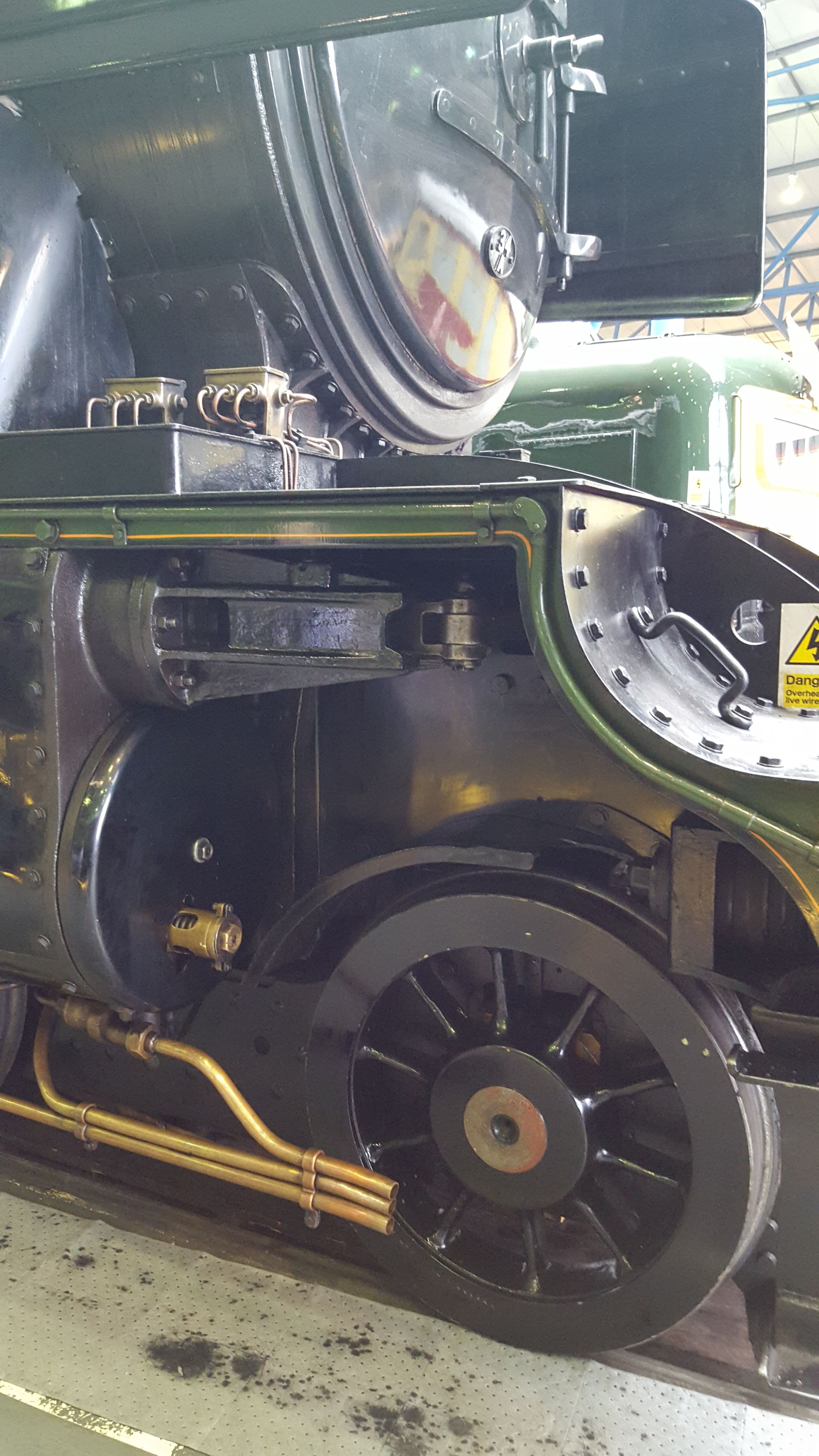
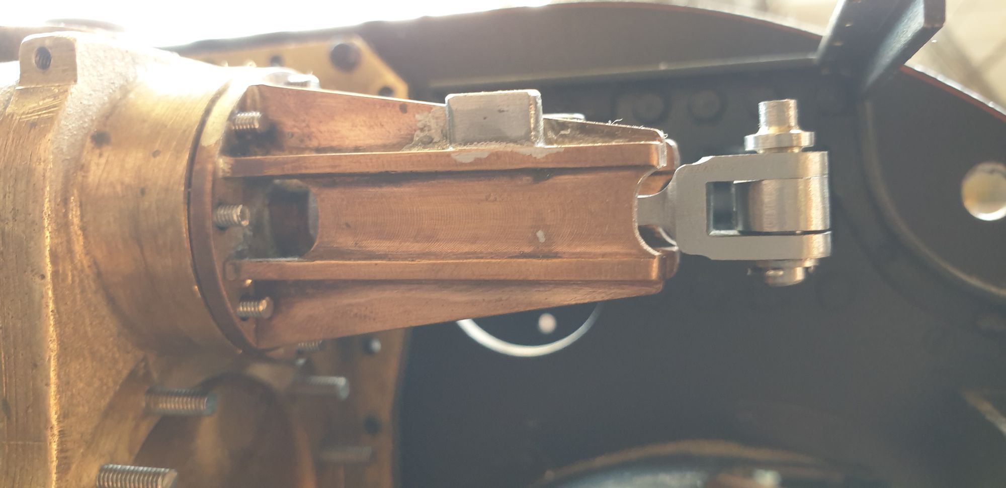
Last two pictures to show how close I am getting to mimicking the full size, it's not far off and Don's drawings are very close to begin with. Details that I have added are the valve guide oil way reservoirs and the small crescent cutout at the front of the valve guide. Once this is all finished and painted it should hopefully, look the part. Looks like I haven't fully engaged the pin either, funny how you don't notice these things until viewing the photos after..:)
And a picture of full size that I took at York 2016.