

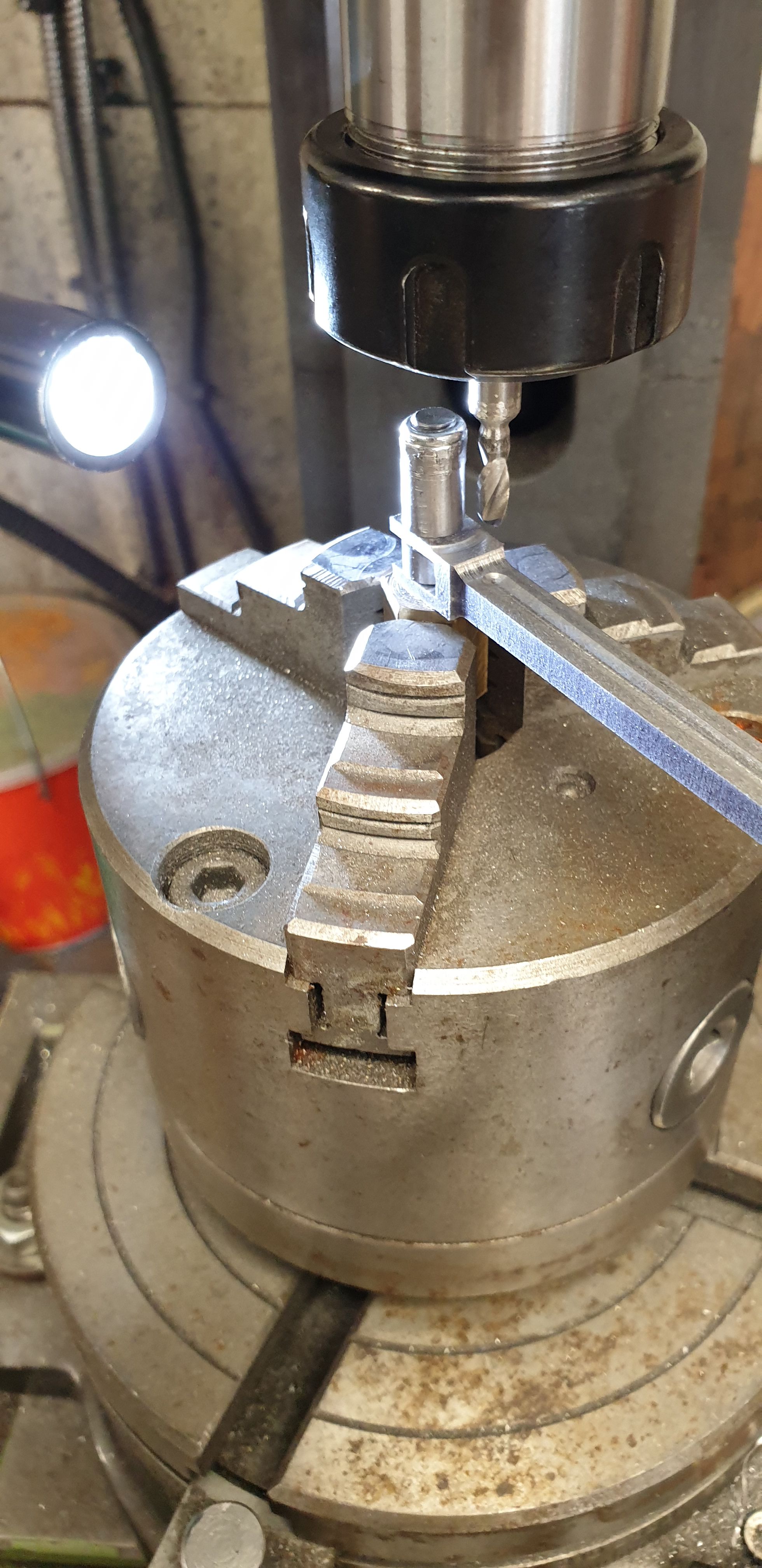
Continuing with the valve connecting links I next machined the small collar around the holes. I have modified these a little to give more metal to the slot tabs, basically I haven't machined as close to the hole as seen on the full size and also allowed a little extra length to the slot itself. Probably 'overkill' but better safe than sorry, here is the middle cylinder link after the collar has been machined using a 3/16 ball nose cutter.
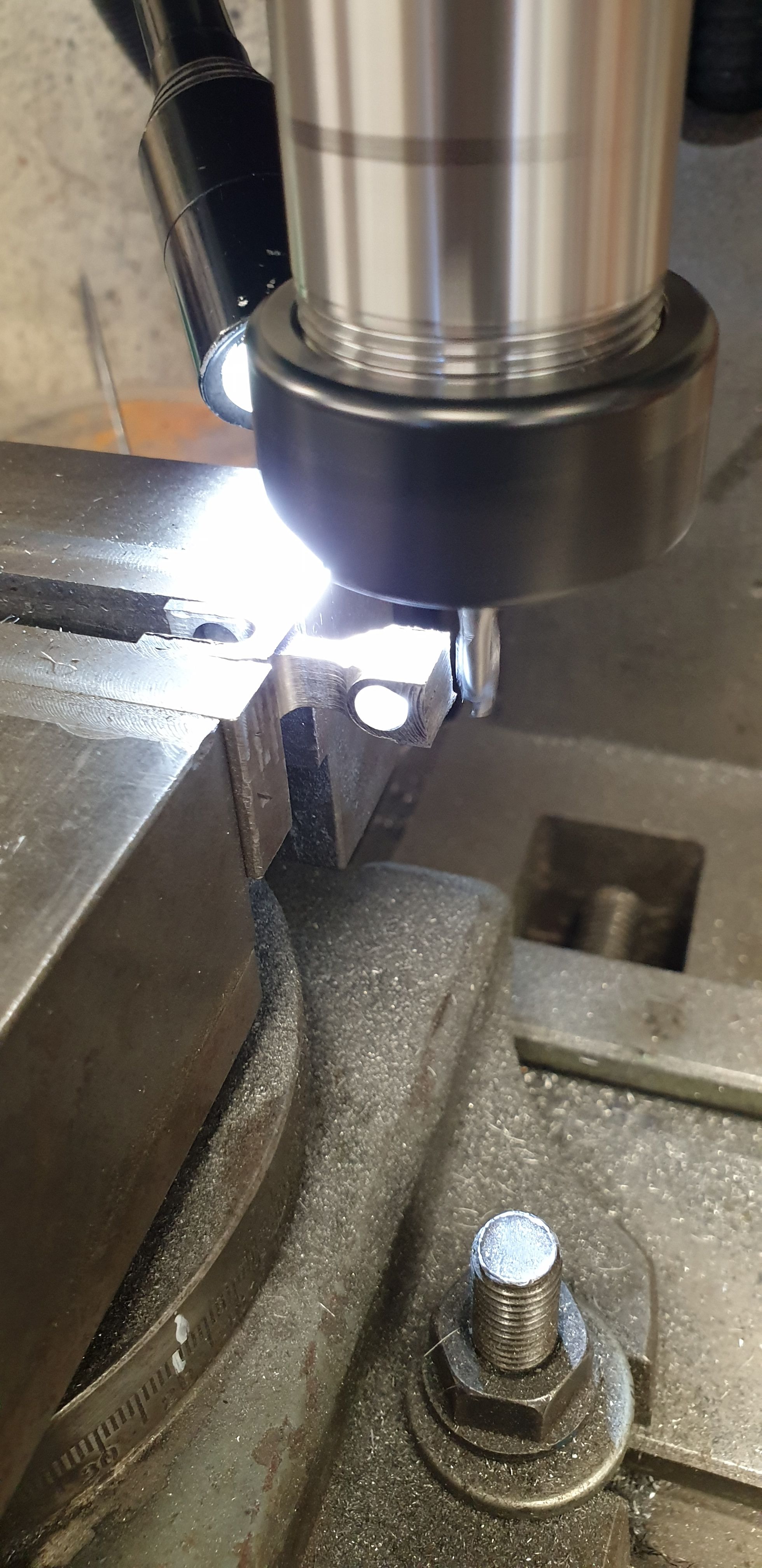
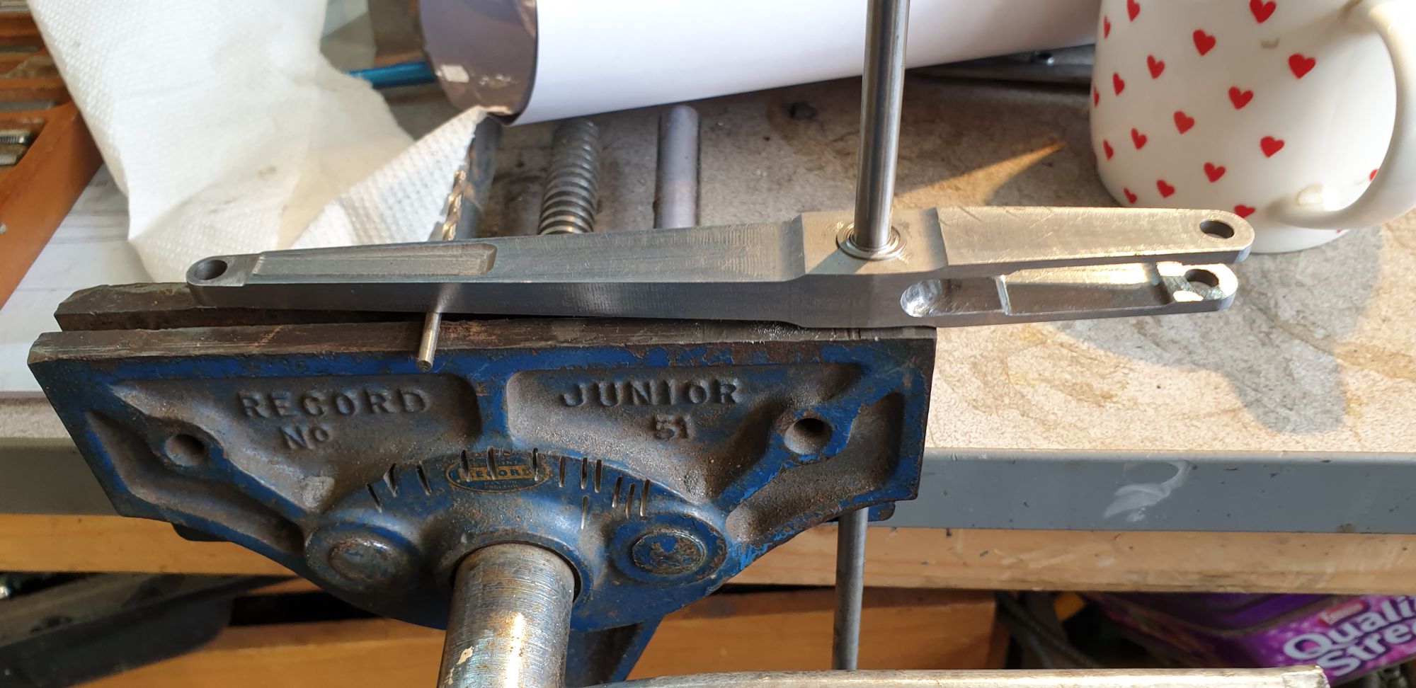
A had one of those 'doh?'' moments here, getting a little carried away when machining the collars. After machining the slot ends I then machined the other ends totally forgetting to reduce then down to 3/16 first? No harm done, just time wasted, the picture shows me quickly holding each link in the vice to reduce the width to 3/16. Here I am machining one of the outside cylinder links. As everything was now setup to center the link in the vice I also took a small gamble and machined the bottom of the slot to square it off by holding the link vertical in the vice (no picture of this). I say gamble as if anything was 'off' it would ruin the work done so far, happily all went to plan. For the middle cylinder link I filed the end by hand as it was too long and the risk too great to machine the bottom of the slot.
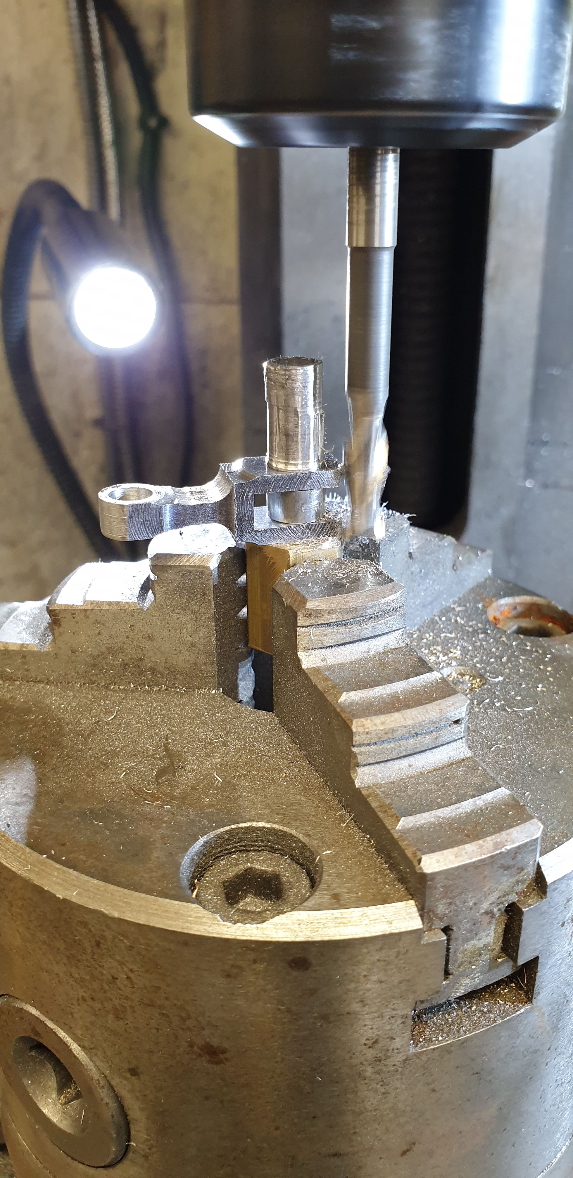
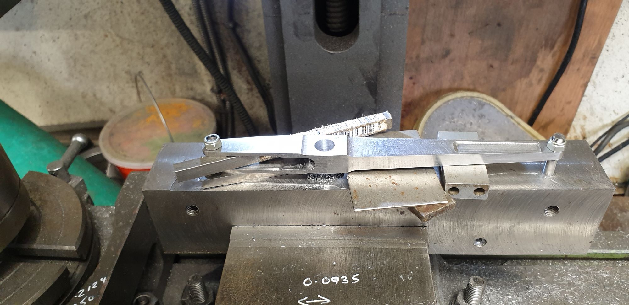
This next picture shows clearly why I didn't machine the collar all the way back on the slot end, you can also see that for the other end this wasn't a problem although again I have left extra material and not continued the rounding into the arm, hope that makes sense? Here I am rounding off the slotted end, this view gives a good idea of the overall shape of these parts, this is the end of the machining but not fully completed as the machine marks need filing and the sharp edges need rounding off, especially the collar edge on the slot end. Nothing that a few hours with file and sanding sponge can't deal with.
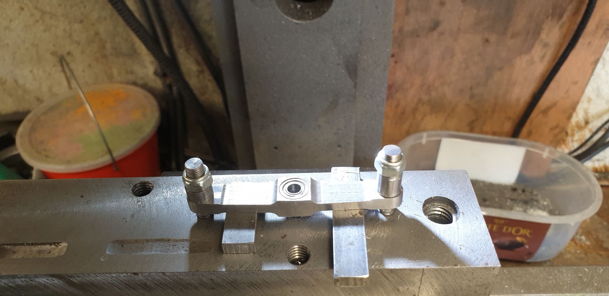
On to the new plan for the 2:1 and 1:1 lever fulcrum bearings, for these I am deviating from the drawings of bronze bushes and fitting sealed/shielded race ball bearings. I have chosen the sizes closest to the original pins, for the 1:1 lever I have found bearings of the same 5/32 ID as drawn. For the 2:1 lever I could find no 7/32 ID bearings and so have chosen the nearest metric size that will fit in the area available. These are 6 mm ID which is not much larger than the 7/32 drawn and 10 mm OD, both sizes are flange'd. In the next picture I have set up the 2:1 lever ready for machining, I have used the same jig as it was built on, once centered It was a straight forward exercise to open up the holes to accept the 10 mm bearing. In the case of this lever I did not need to machine a recess for the flange as there is plenty of room in the 2:1 stay, it seems that my idea to increase the gap between the two fulcrum bushes has come in handy here.
Here we see both bearings now fitted, I have used a Loctite retainer to secure the bearings and left for a while for the retainer to cure.
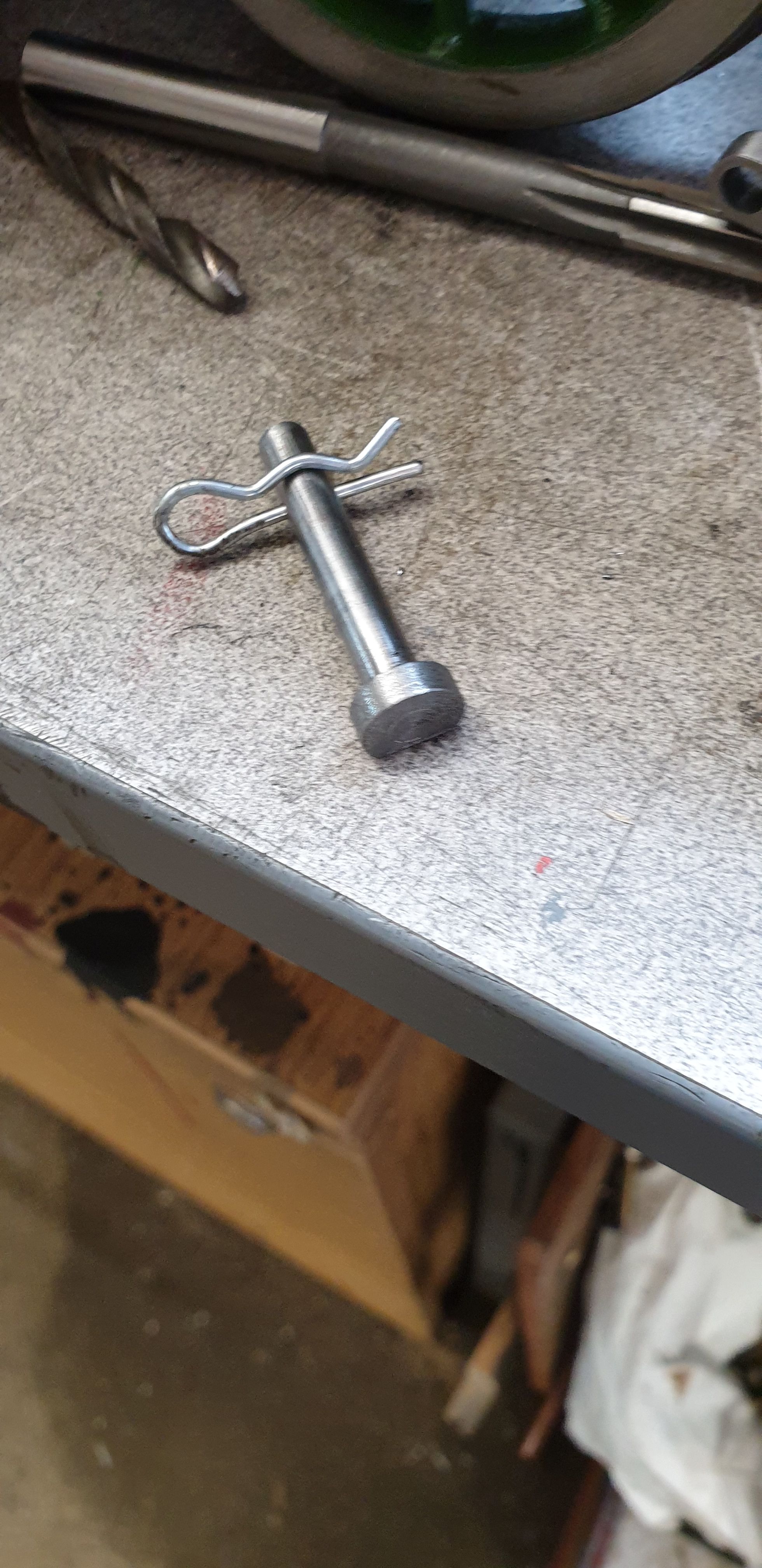
The next job was to make a new pin to fit the 6 mm ID, I have modified this too thanks to a tip received. I have machined a flat face on one side to stop the pin from spinning, as can be seen I have also drilled the hole for an 'R' clip. I have done this at 90 degrees to the flat edge, the reason for this will be seen in the picture after this one.
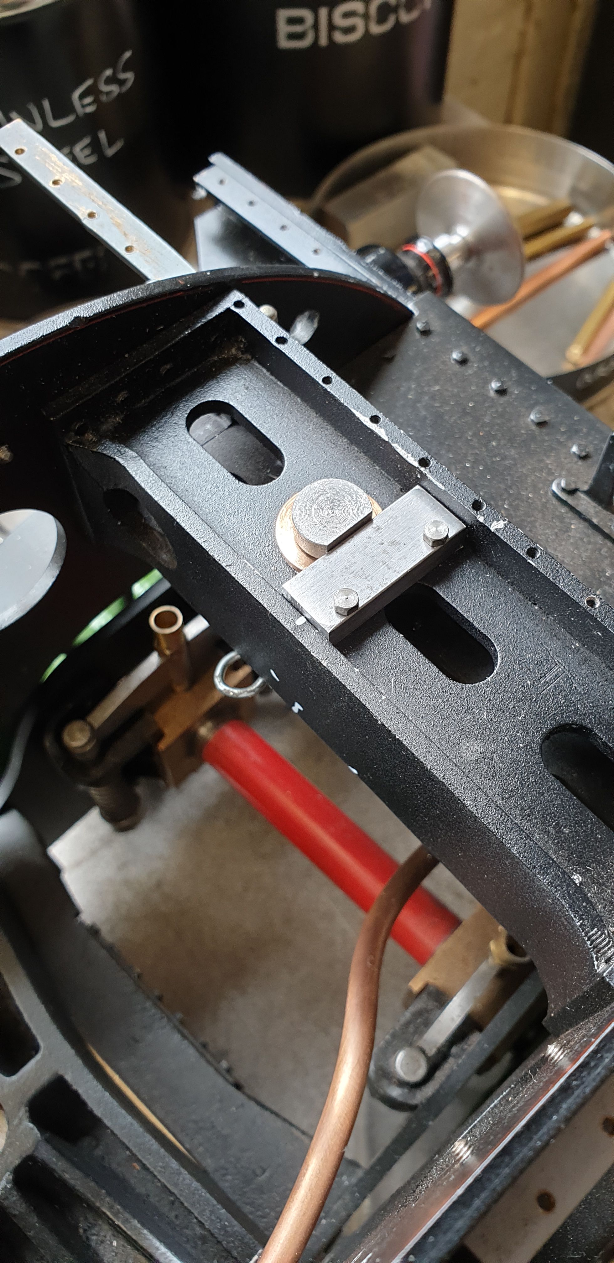
Another modification, this one to the 2:1 gear stay, I have added a location stop for the flat edge of the pin to sit against. You can see the 'R' clip poking its head out from below, it's not fully pushed home here, I've left it sticking out to show its orientation. I have made these parts to follow my plan of making everything very easy to access/maintain. I can easily reach the pin and the stop mounting screws (8BA) through the middle running board hatch and thus I think that if anything fails on the 2:1 gear it won't be a big issue to remove it in its entirety and fix any part that may require my attention. I have used an 'R' clip to help in this as a spit-pin would be more problematic and since this clip can not be seen it seems like a reasonable solution.
This left the 1:1 lever to deal with, here there's a little more work as I needed to machine a step for the flange to sit in as there is no space between this and the 2:1 lever fulcrum point. These are 5/32 ID and 8 mm OD, the flange comes out at just over 9 mm. The bearings are 1/8th wide which gave a little space between the two after machining the step for the flange.
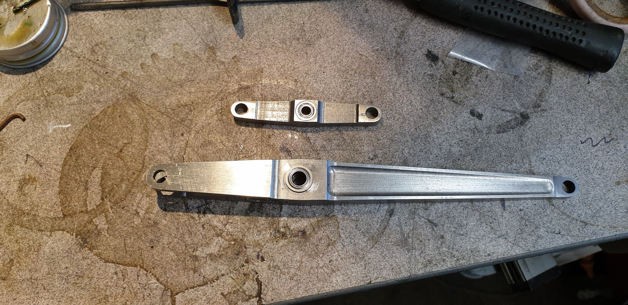
Last picture for this entry, here's both lever's side by side with their bearings now fitted, they are semi cured, I left them at this point to give them time to fully cure overnight.
Things are getting close to being finished on the 2:1 gear now, in the next update I will make the pins/bronze bushes and give the various parts a final polish/file ready for assembly.