

Valve connecting links
These are another one of those parts which require a number of setups and a little thought in machining them, this is how I have tackled them.
First job was to cut up 3 lengths of 5/8 x 3/8 gauge plate, 1 longer than the other two and then machine them down closer to the required size. I cut these over-length allowing for the CTS distances of 3 31/32 for the middle cylinder and 27/32 for the two outside cylinders. The dimensions are 3/8 by 5/16, I machined the 3/8 to size but left the 5/16 a little over-size as 5/16 is the RAD dimension.
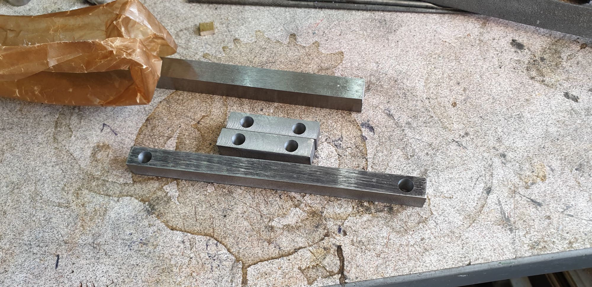
The first picture shows the 3 links roughed out and drilled/reamed to 7/32, the stock material is behind, next time I'll look for something closer to size to save time.
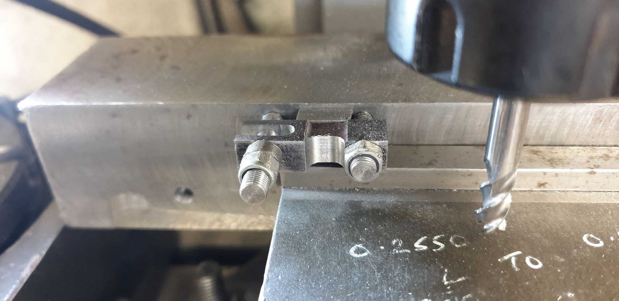
Next I chain drilled and machined the slots open to 3/16, holding each link in the machine vice to do this. I then drilled more holes into my lump of steel (jig) to mount the links, I drilled all 3 CTS so that I can zero one end and use it for all 3 links to keep them the same. I did the long link first, the first job was to reduce the middle section from 5/16 down to 1/4, I have left the center oversize on both axis for extra strength. I did this first due to Don's warning about fluting both sides and also from other comments that I have picked up about the required strength of this particular part to ensure accurate timing at speed. After doing the first side the positions were noted and the other side was then machined on the back edge.
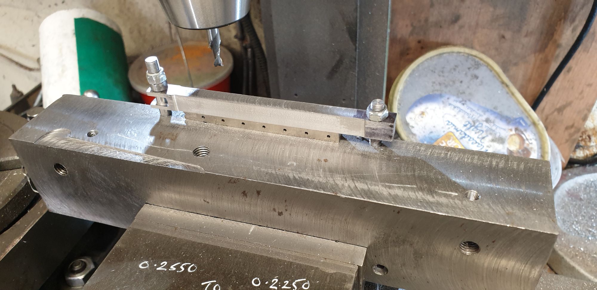
I then did the same to the two small links, depth of the recess is the same but ,of course, much shorter. I left the left hand stud in the jig and moved the right hand one to the other hole drilled/tapped for the shorter links.
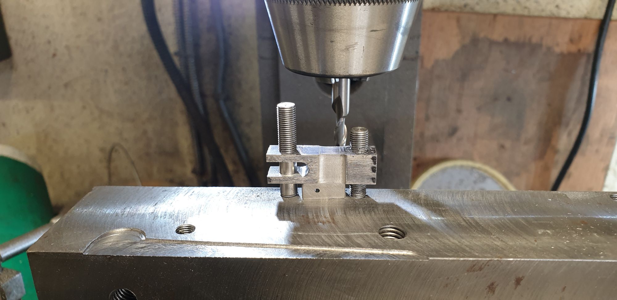
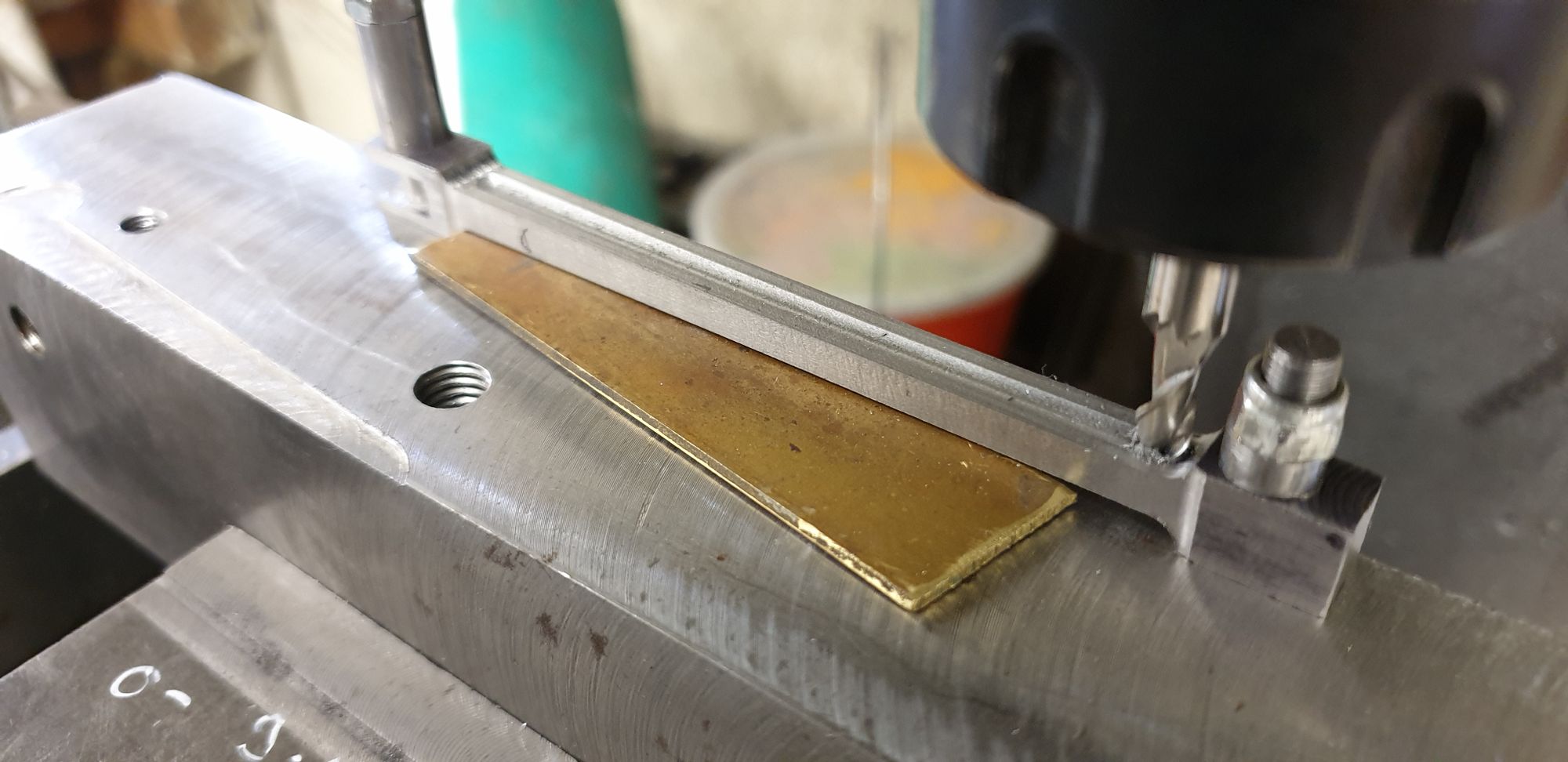
It was then the turn of the top/bottom faces, first job was to flip the jig into its upright position, the jig was drilled offset to make this very easy. These faces are reduced much further that the sides, again, I have left extra meat on the middle link to ensure the extra rigidity that this part warrants. Here I have already machined one face and flipped it other to do the opposite face, packing was used to ensure the cutter had pressure when machining. You may note the white marker pen notes, these were to remind me of what I did for each session, I usually make pencil notes on the drawing but find this much easier to keep track off what I'm doing easily.
With the middle cylinder link done I then did the same to the two outside links, this was very short but also much deeper than for the longer link.
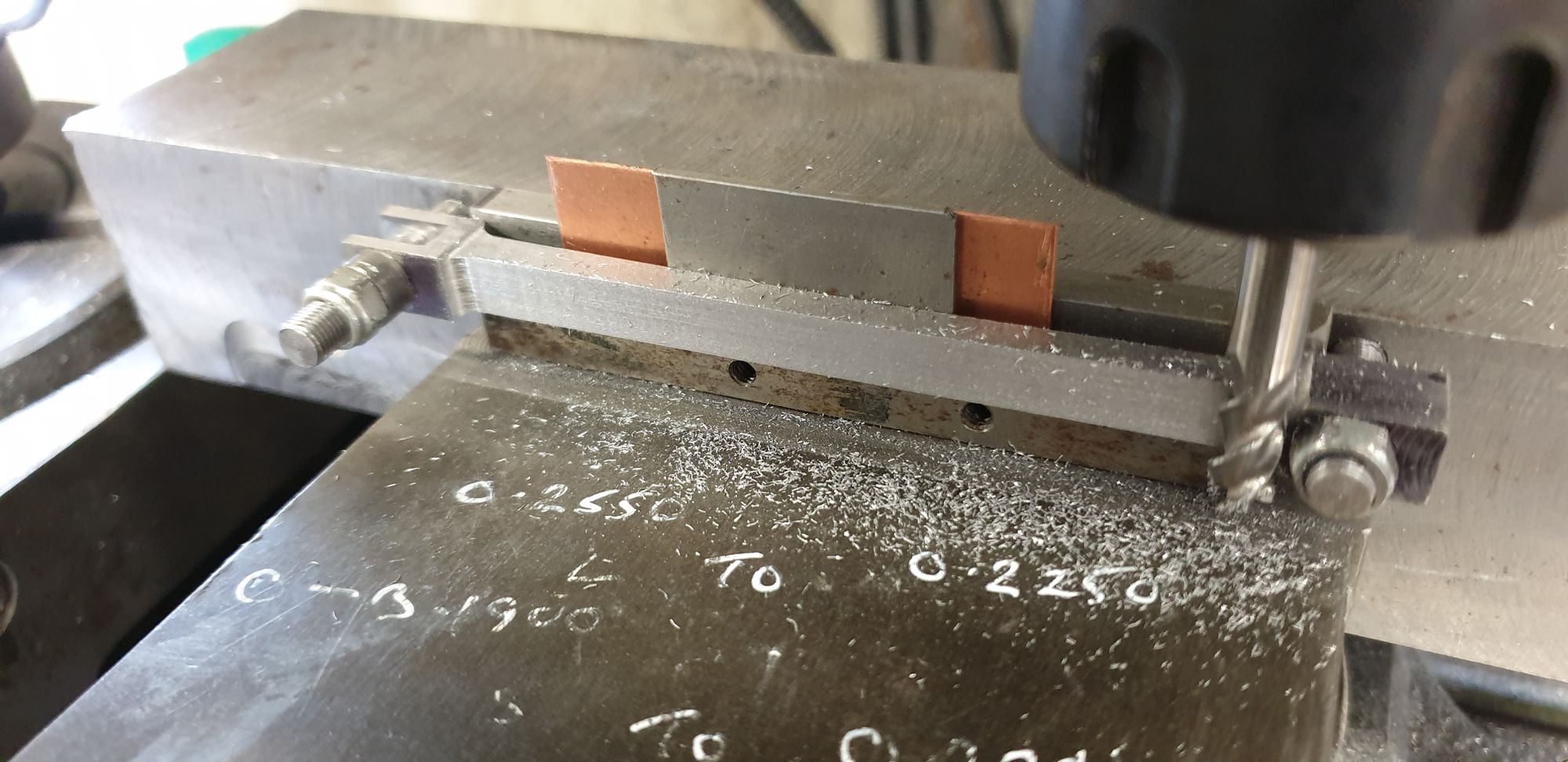
The jig was then up righted and the fluting was machined along the long link only, no flute on the two smaller links. Now Don stated that the link may be too flimsy if fluted both sides as per prototype, I hate bare rods unless that's how they are supposed to be. Because of Don's warning this is why I have beefed up the middle section of the long link, I have cut flutes on both sides but these are much shallower and narrower than the prototype, I decided that I can life with this but not bare metal. No one will ever see it but hey, I know that I spent the time to give some representation of fluting...:) I still need to reduce the tail end, (right hand tab in this picture) to 3/16 for it to fit into the valve cross-heads, I haven't done it yet as I wanted to have a solid level base to machine the flute on.
Next update I'll hopefully finish the links and the pins and have an assembled 2:1 conjugated lever. I will also describe a change to plan as I'm now fitting ball bearings for the 2:1 fulcrum pin and the 1:1 equaliser lever pin, just like the prototype.