
Onto the final machining operations for the 2:1 lever, I'll make the bronze bearings in one batch once I have made the 1:1 lever and the 3 connecting links as except for the fulcrum pin they all share the same bearing specs.
Before moving on to the fluting I first needed to open up the section of the slot to allow the connecting rod knuckle to fit. Don states to open this up leaving 0.070 metal either side, he says it looks thin but is strong enough for the job in hand. I have changed this a little and left 0.080 of steel either side, I'll adjust the size of the connecting rod knuckle to suit.
With the basic shape now profiled as per drawing i then turned my attention to the fluting. Before doing so I must point out a change from Don's drawing, if you look back at the drawing, Don shows an angled face from the fulcrum up to the fork prong's, this is also mirrored on the inside of the slot. I looked at this and although machining the outside would be easy enough, filling the slot to match would be a bit of a chore, not to mention the whole part would have less strength. I therefore have chosen to omit this small angled face. Ok, so the flute, I have set the lever up on the large lump of steel which was used for the coupling rods as it is heavy and very rigid, perfect for this particular job. I plotted the lever holes (drilled/tapped) parallel along the jig and turned up a bush to fit the fulcrum to accept an 8 mm bolt. For the two ends I have used some 7/32 silver steel which I threaded either end to complete the 3 mounting points.
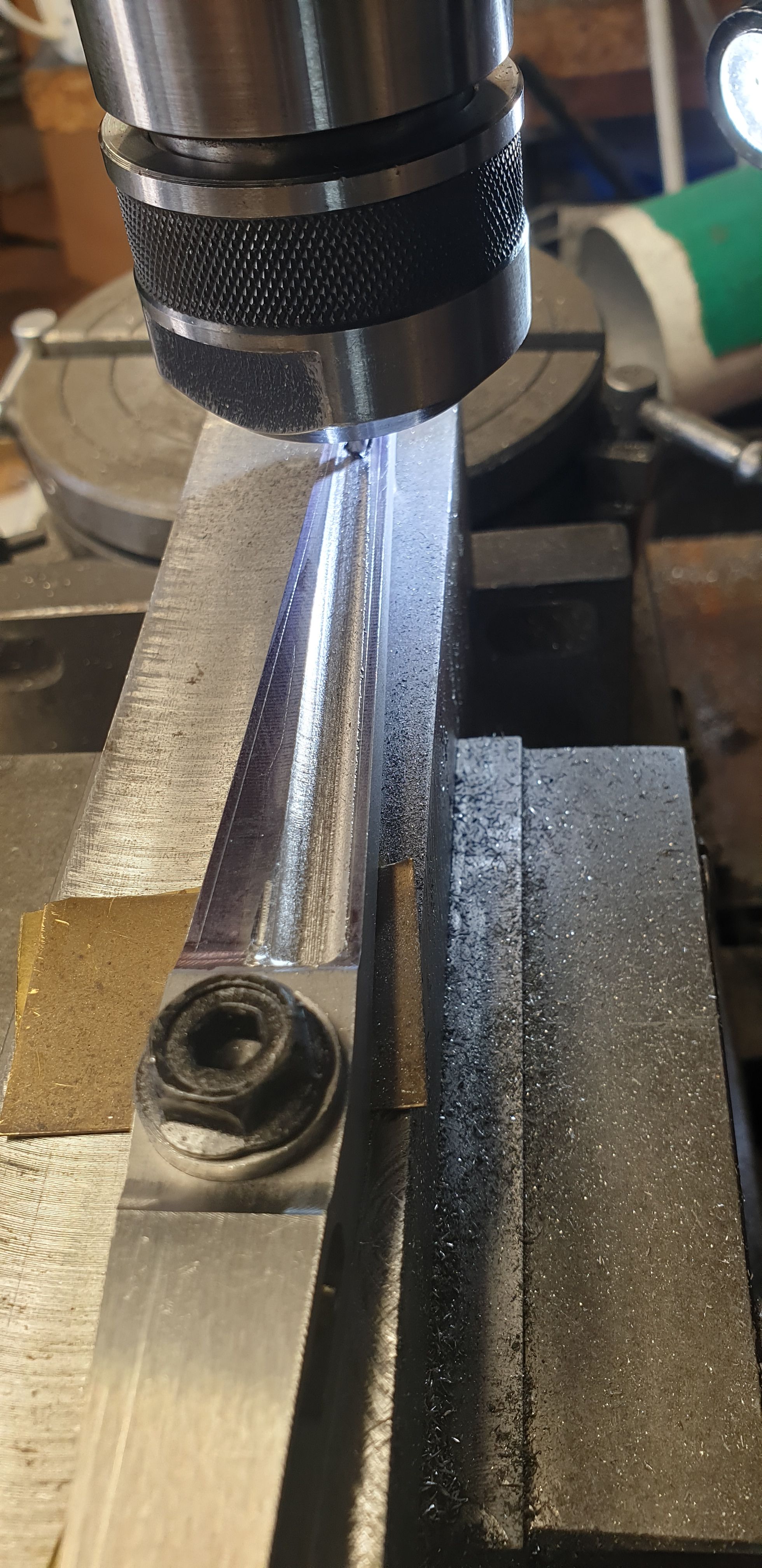
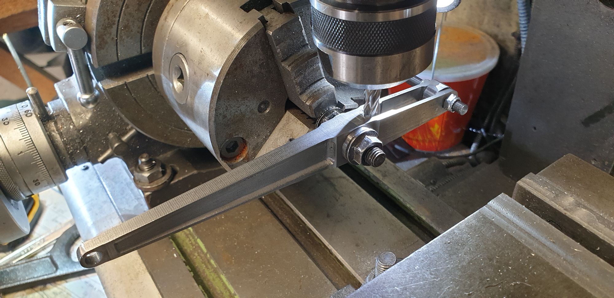
The first picture shows that I have begun to machine the flute, I have chosen to use a 3/16 ball nose cutter and for extra safety I am using the auto-lock chuck to hold it. I clocked the angle off the edge for this first stage, I also have ascribed a line down each side as a visual guide. You can see that the cut isn't following the line, well actually the cutter is but due to the angled surface that I'm machining and the fact that I'm using a ball nose cutter it of course tails off towards the thinner section. when starting to machine this part I worked from a short distance from the widest end and cut up close to the fulcrum, doing this meant I avoided any 'plunge milling'. I continued to do this on the one 'Y' setting until I had both reached either end and also was down to the required depth at the fulcrum of 1/8th. Once at this depth most following operations were done with 'Z' locked, just requiring the one time to lift a little to reverse the job in the vice for the opposite angle, this helps greatly in avoiding machining lines in the flute.
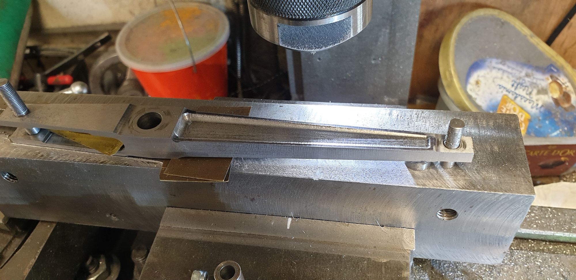
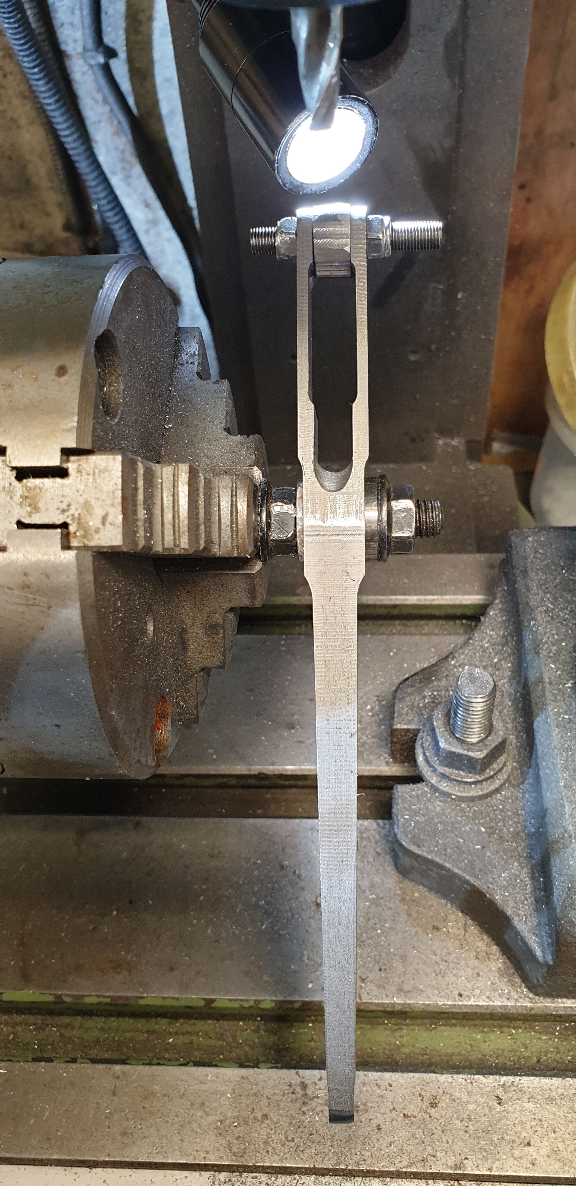
Once I had reached the stage shown above I then adjusted the angle so that it followed the required line, an easy thing to do when using a swivel vice. I completed the machining on the first side and with the angle now set, turned the part over and machined the other side being confident that the finished cut would match the ascribed line. This was the only time that I lifted 'Z' a short distance, yes I know that the DRO should put me back where it belongs but that doesn't always work if the cutter digs a little, better safe than sorry is my approach. The last machining operation for the flute was to reset the job parallel and machine the two ends. The thinner end needs to be rounded off, I'll do that by hand later. Here's the flute for the top side.
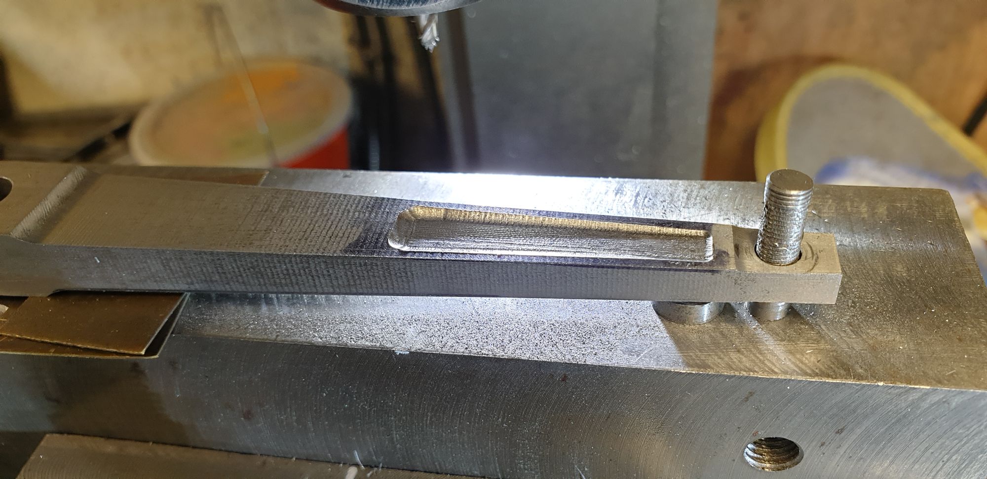
For the underside I have only machined the area which can be seen from under the loco, well life's short enough, I have plenty of things that can be seen to take up what's left of it...:)
Now I had the two tricky bits to do, actually one of which Don says can't be done machining wise, I disagree although since Don wrote his words describing everything on this model to be machined just using a Myford lathe perhaps he has a point although I think it should pose any real concern? I tip my hat to anyone who manages to build this model fully just using a Myford?
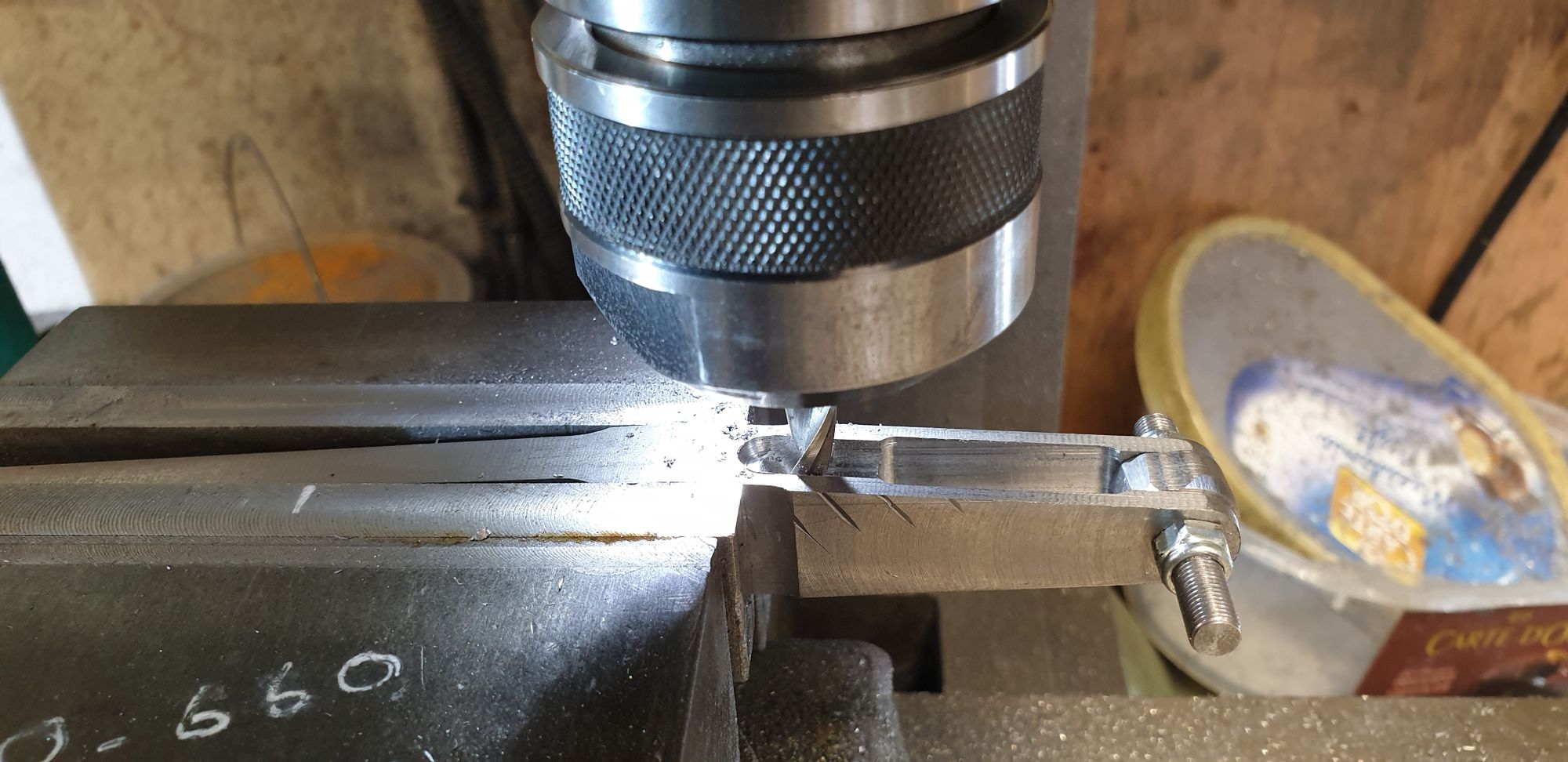
OK, so the first part is to continue the slot rad around the fulcrum, using a rotary table makes this pretty straightforward. When I say tricky I'm not referring to the machining itself, more the fact that if anything goes wrong at this stage, that's one hell of a lot of work to have too repeat.
Here we see it side on, the slot is tapering as I couldn't get close with the auto-lock chuck but it's not an issue as the next job will take care of this.
The last job is what IIRC Don describes as a kick back rad and why he says it can't be machined. The slot you may recall is 9/32 wide and your's truly just happens to have a 9/32 ball nose cutter which makes this job very easy when held in the machine vice, the final part involving a little filing.
I have taken the picture from this side to show a mistake that I made early on, in fact it was the first profiling operation when I cut the 3/16th tab for the narrow end. I hadn't fully tightened the vice which resulted in the cutter pulling the job through the vice jaws and leaving these gouges along one flank. All other signs have since been machined away as the profile took shape just leaving these 4 lines as a reminder to me not to be so forgetful next time. In my defence, to date I have very little in the scrap bin, one warped tender sole plate from getting it too hot and the trailing wheel crank-pin caps, which although are fully serviceable the threads felt a little loose and so I made two more with tapered threads, I don't think that's at all bad for 11 years work. Naturally I chose this side as the underside.....:)
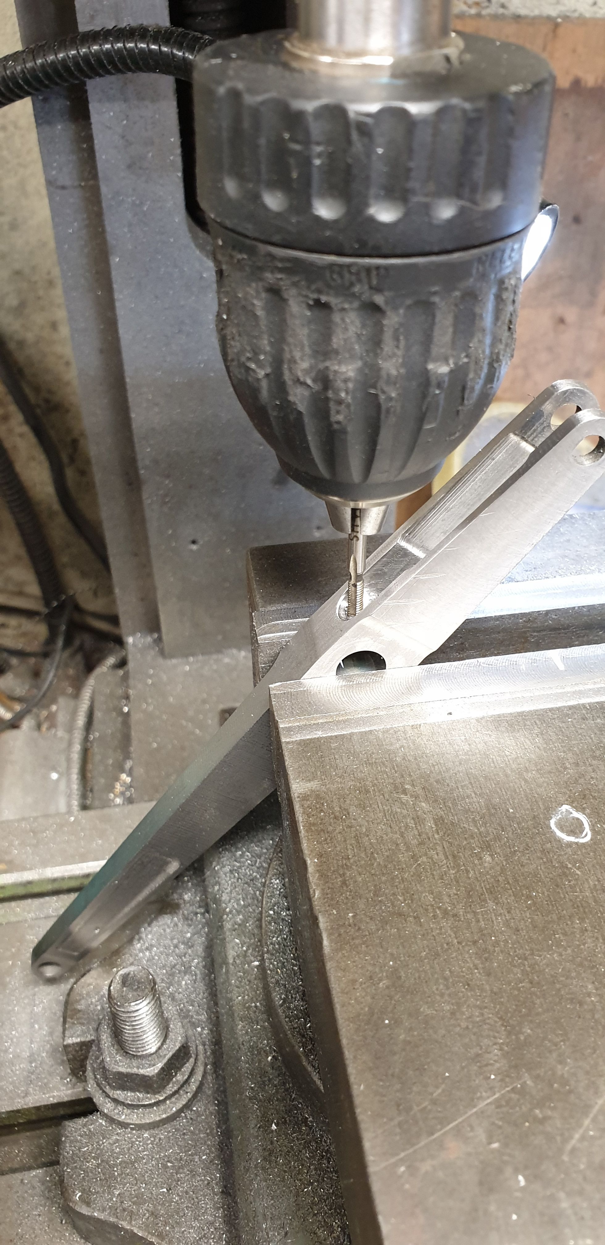
The last job to do was to drill/tap 6 BA the oiling point for the fulcrum bearing, as with full size this is accessible via the small hinged front door. Perhaps this opening is why the 2:1 fulcrum bearing had maintenance issues during the early years of the class. At first there was no door just an oval opening which must have allowed a lot of ash to get in, this was then covered with a small hinged door which is what my model has for the late 30's. Later there was a complete redesign and the small oval opening was changed to a wider rectangular slot which had a sliding hatch, this is how FS is today.
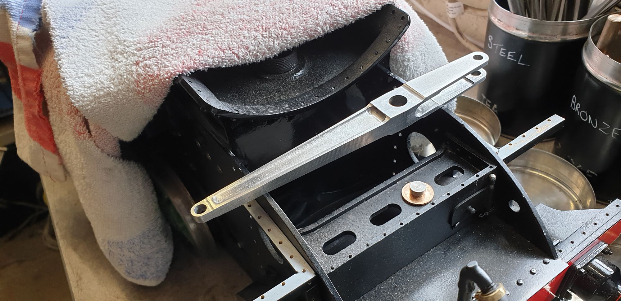
The final picture is to show the finished article, all bar the bearings of course. I spent a couple of hours removing the sharp edges and machining marks using files and sanding pads to get it looking as close to full size as possible, mind you most of this will be hidden from view, still, I will know even if no one else can see it that I made the extra effort...:)

Next will be the 1:1 lever and the 3 connecting rods