
I have now cut the axle keyways and as long as they are correct ( pretty confident of this) then I guess you could say that that's the quartering taken care off, well it is as long as I broach the wheel bores exactly along the centre line between axle and crank pin that is.
So a little description of how I tackled this utilising both the advice given by fellow model engineers and what was practical with the components built so far, IE axles already cut to size.
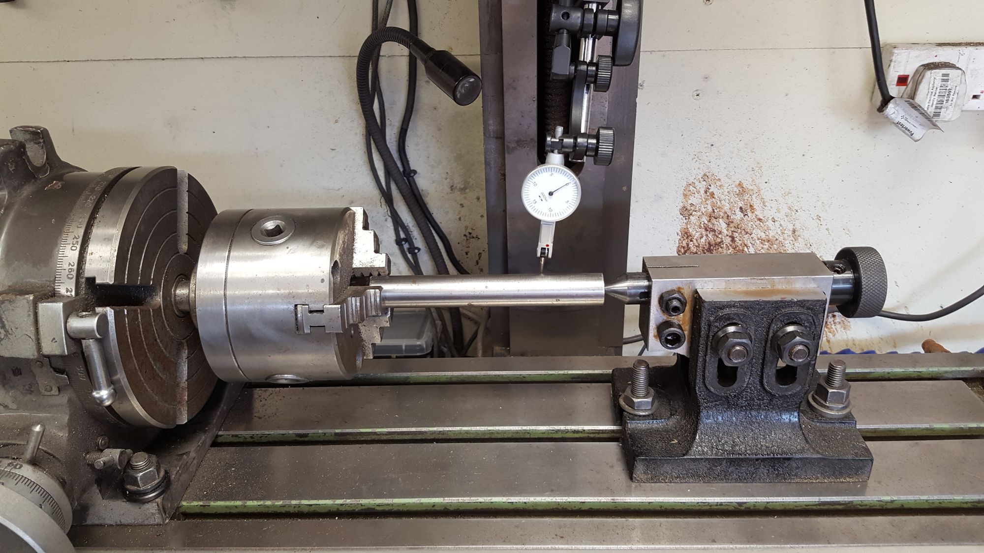
Before describing the first picture a little preparation was needed, naturally, the rotary table and tailstock were clocked so that the axle was both parallel and horizontal to the X axis, I took a lot of care here. I also gave the position of the chuck jaws a little pre-thought and adjusted the chuck in the table so that when I cut the left-hand keyway I would be machining between jaws.
Ok, so we start with the R/H keyway, ( just to remind people, the axles were machined to size some time ago) the method employed was to set the table at '0', turn clockwise to 113 degrees and cut the first keyway of which the start is shown here. The size is a 3/16 cut and 95 thou deep, I did a little reading before arriving at this depth, 95 thou being what Tubal Cain advises. On further reading, checking info for imperial English cuts it's dimensioned at 3/32 or 93.7 thou (half 3/16) from the flat, IE after removing the radius, so 95 thou from the rad seems good enough to me. I did the cut slowly in 20 thou segments to a length of .700, this is over the wheel thickness but should mean the the key stops at the end radius and thus fully engaged with the wheel, there isn't any room between wheel and axlebox to have any sticking out.
Now to the tricky part, only tricky as I had followed Don's words and already cut the axles to length, not very practical for cutting keyways but then Don describes doing the quartering in the more recognised practice of using a jig. I prefer using the rotary table which in my mind is more accurate, having seen Eddie's fine builds on his fine K3 and H1) I could see the merits of doing it this way.
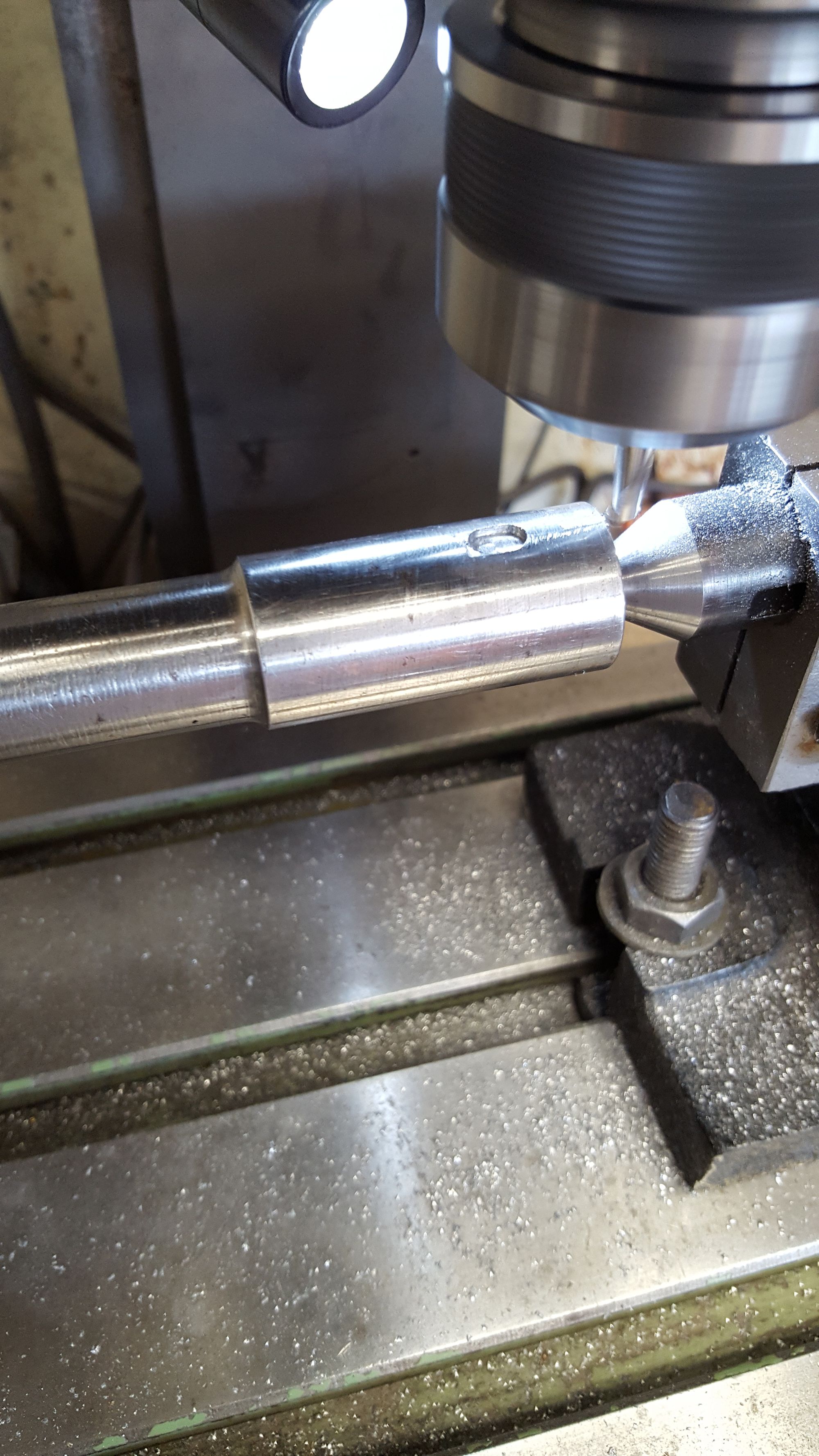
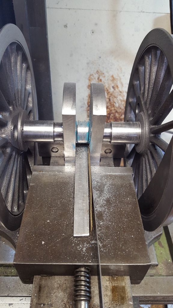
Picture, shows a start having been made on the L/H keyway, the axle was clocked a further 120 degrees clockwise before cutting. Not wanting to start with a plunge cut I took the cutter 'off centre' and came in from one side having first set the DRO at zero for Y axis centre. Once I had machined back to the centre line I resumed cutting the keyway slot for as much as the chuck allowed, for now, I only machined down to 50 thou using small plunge cuts in the middle of the slot. hope that makes sense. The pencil line is just to keep within the .700 length required. I'll come back to finishing these.
Next was to cut the central keyway for locating the crank webs, of course, this is not required on the leading/trailing axles. The table which was at 233 degrees for the L/H cut is moved on (still clockwise) a further 127 degrees to 360. The slot is made across the entire central section (to be removed later) so that both webs will be held exactly in line with each other.
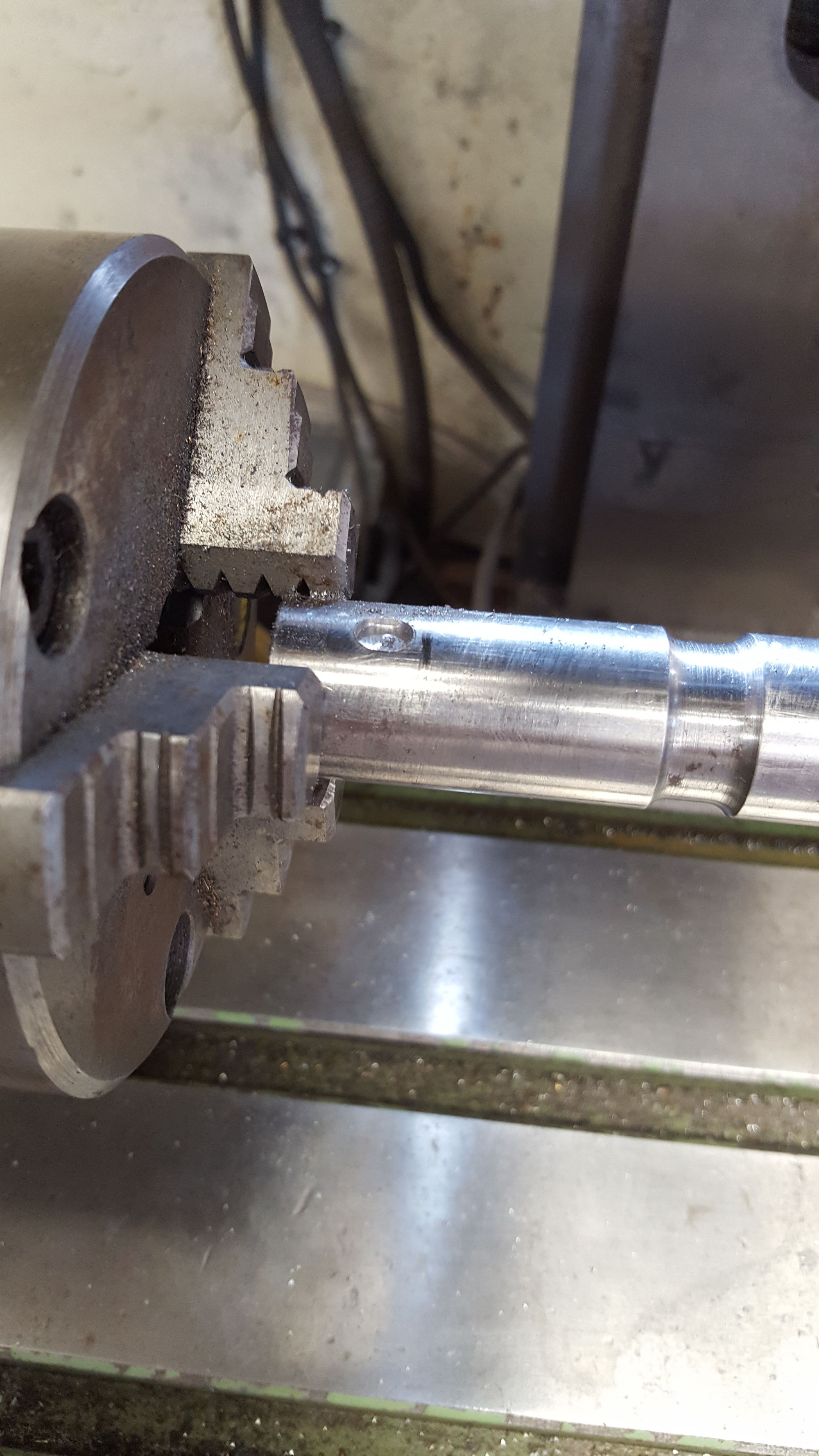
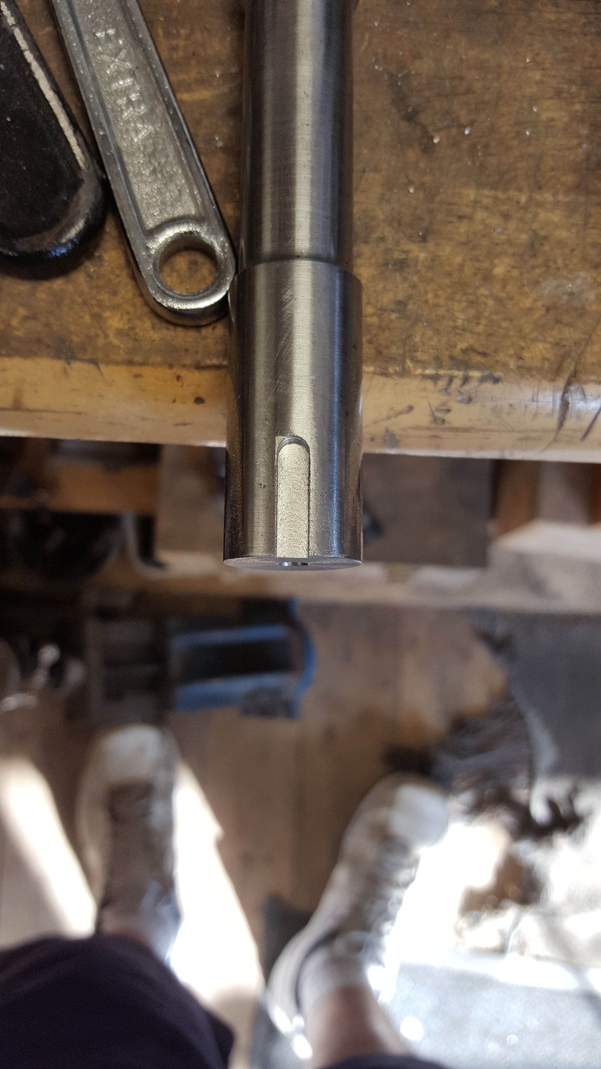
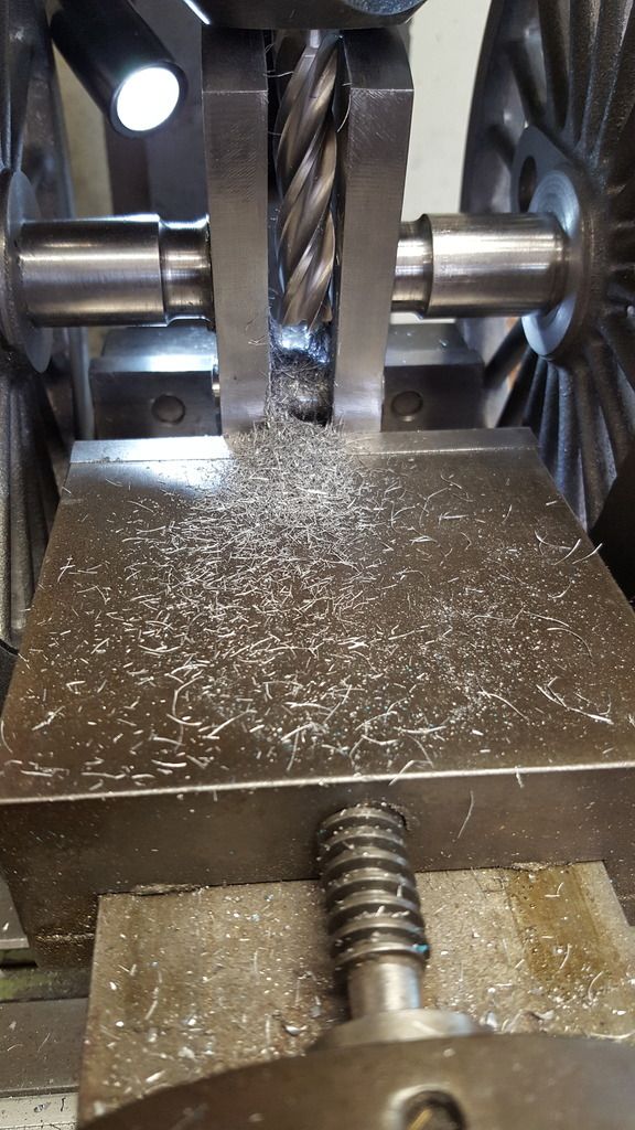
Ok so after all 3 axles were to this stage I needed to reverse the axles in the chuck for finishing off the L/H keyway. I was a little concerned about this but actually it worked out well, I first set the rotary table at '0', locked it and then played around with getting the R/H cut back on TDC, this turned out to be a lot easier than I expected. Method employed was to have the axle loose in the chuck and twist it to match the cutter when lowered by hand with the quill disengaged. I found with a little pressure of cutter into slot the axle would more or less self-align, carefully tightened the chuck and then checked for free rotation within the slot, first by hand and then under power. After being happy that all looked good I re-engaged the quill, set 'Z' axis ready for machining the slot to 95 thou. I then continued the clockwise motion and moved the dial 240 degrees to see if it matched the small slot already cut, I'm very happy to say that it did. Not the ideal way of doing these but all that I could think off with what I had to hand. Picture shows beginning of cut..
And then to show how well the slots matched up..the flat edge seen on the left is where I first machined in from the edge to avoid an initial plunge action which could have made the cutter run out.
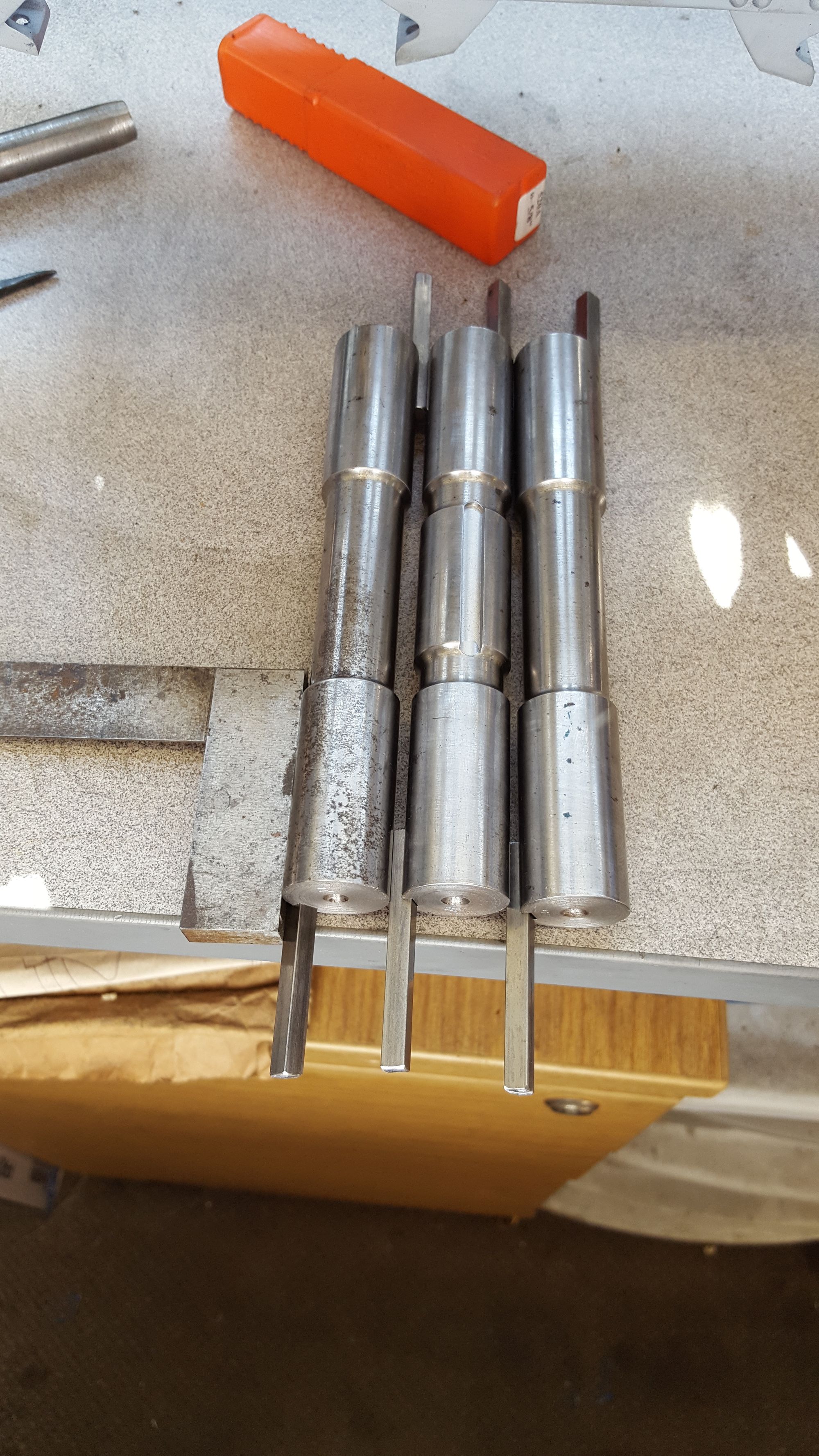
Final picture (R/H side)to show all keyways have been cut, the axles aren't exactly lined up but as close as I could get them whilst trying to show the crank axle's central keyway, keys put in place to show their relative positions.
I then made a start on the crank, only the holes so far but since these are critical I will post my progress now with plenty of pictures to show how I've tackled this job so far.
First I cut up 3 blanks, two for the webs with the third (slightly smaller to save material)to be used as a jig for broaching, the material thickness required is 7/16 , I only had 1/2" EN8 in stock so have used that. I did get a little ahead of myself here, I forgot to machine the blanks down to 7/16 before starting, no problem I'll do it later before shaping but it would have saved me some time if I'd remembered...lol
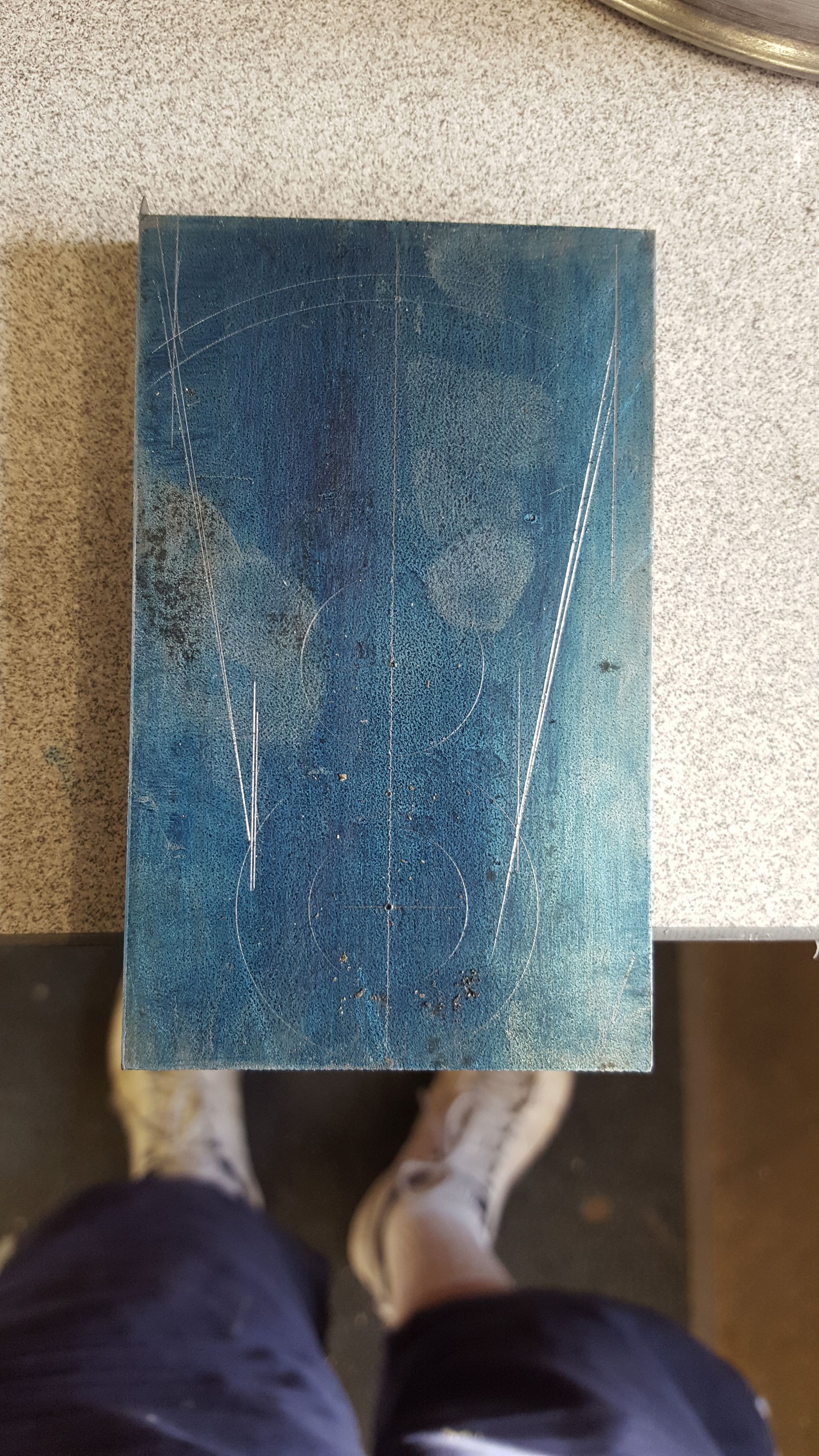
First picture shows one blank blued and marked out roughly just to give me a visual of what's going on, I mismeasured the large arc which was then redrawn hence why it looks a bit of a mess, the crank centre's are there but only as a guide, for this very important measurement I'll let the DRO do the talking.
So on to setting up, I had a couple of things to consider, squareness to the x axis and to keep the job off the mill bed, to do this I used my trusty right-angled steel section that has been drilled to fit the T slots, this was placed at 90 on two short lengths of 1/2 square MS long enough to support both the right-angle and the crank blanks. With the right-angle lightly tightened down and with a large section of steel on the other side of the blanks I used a large engineers square to get everything as required, once happy, the right-angle was fully tightened. The 3 blanks were glued together first with a spot of Loctite 638 in each corner and left overnight to cure.
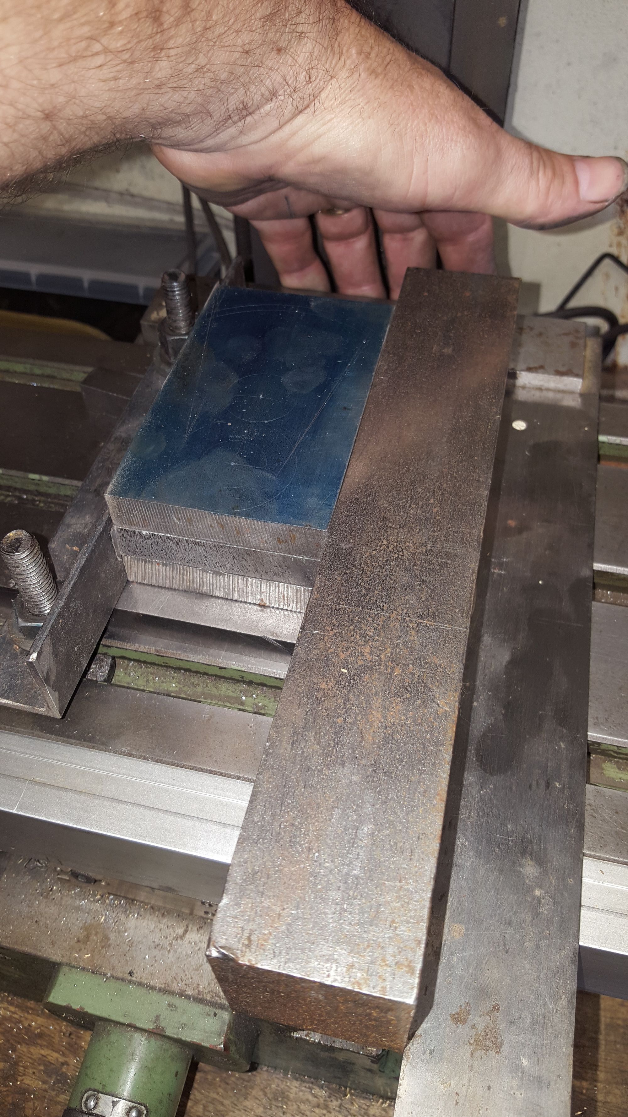
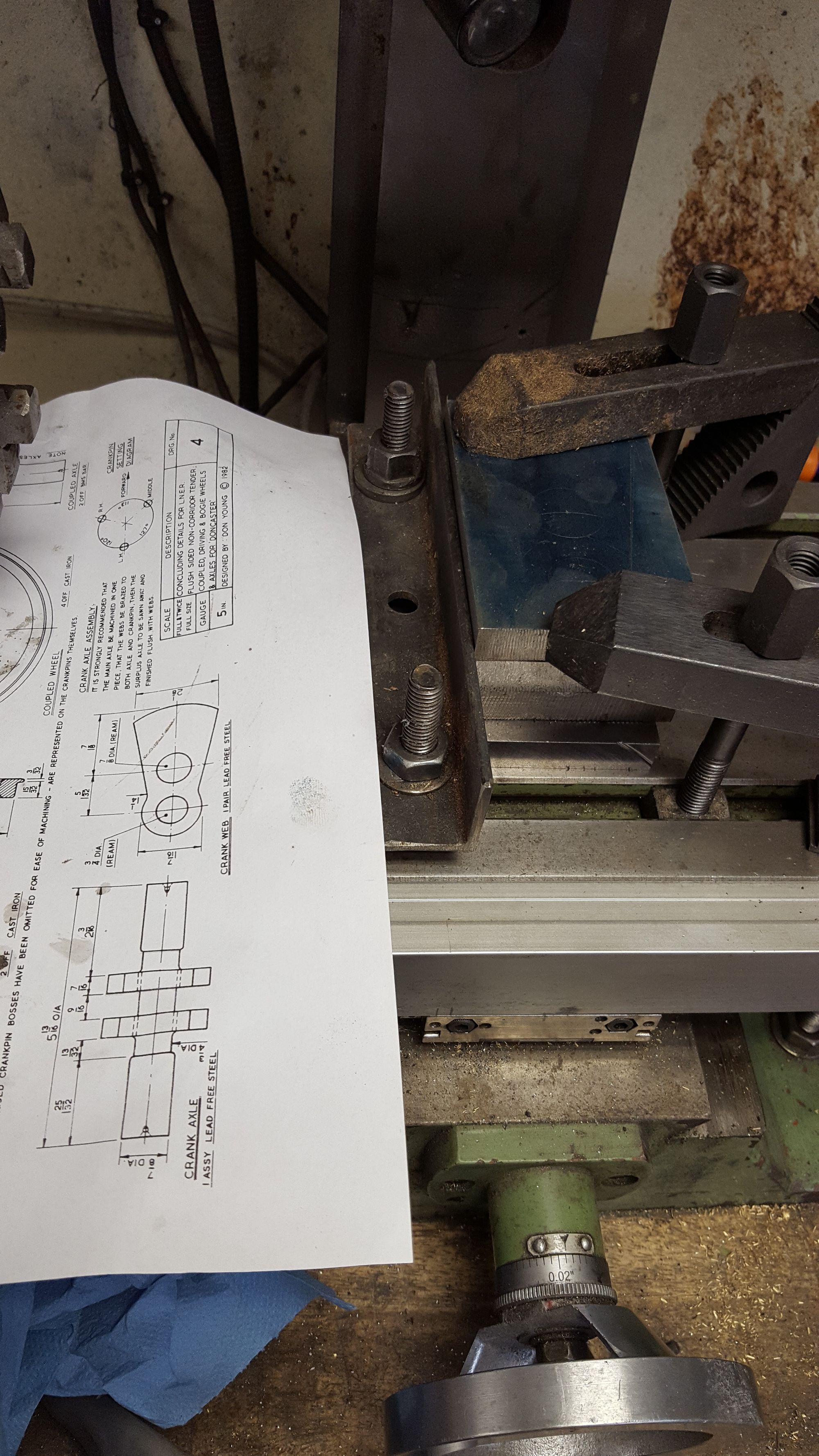
Next picture shows the blanks held down tightly with clamps and a printed drawing of the crank nearby for reference.
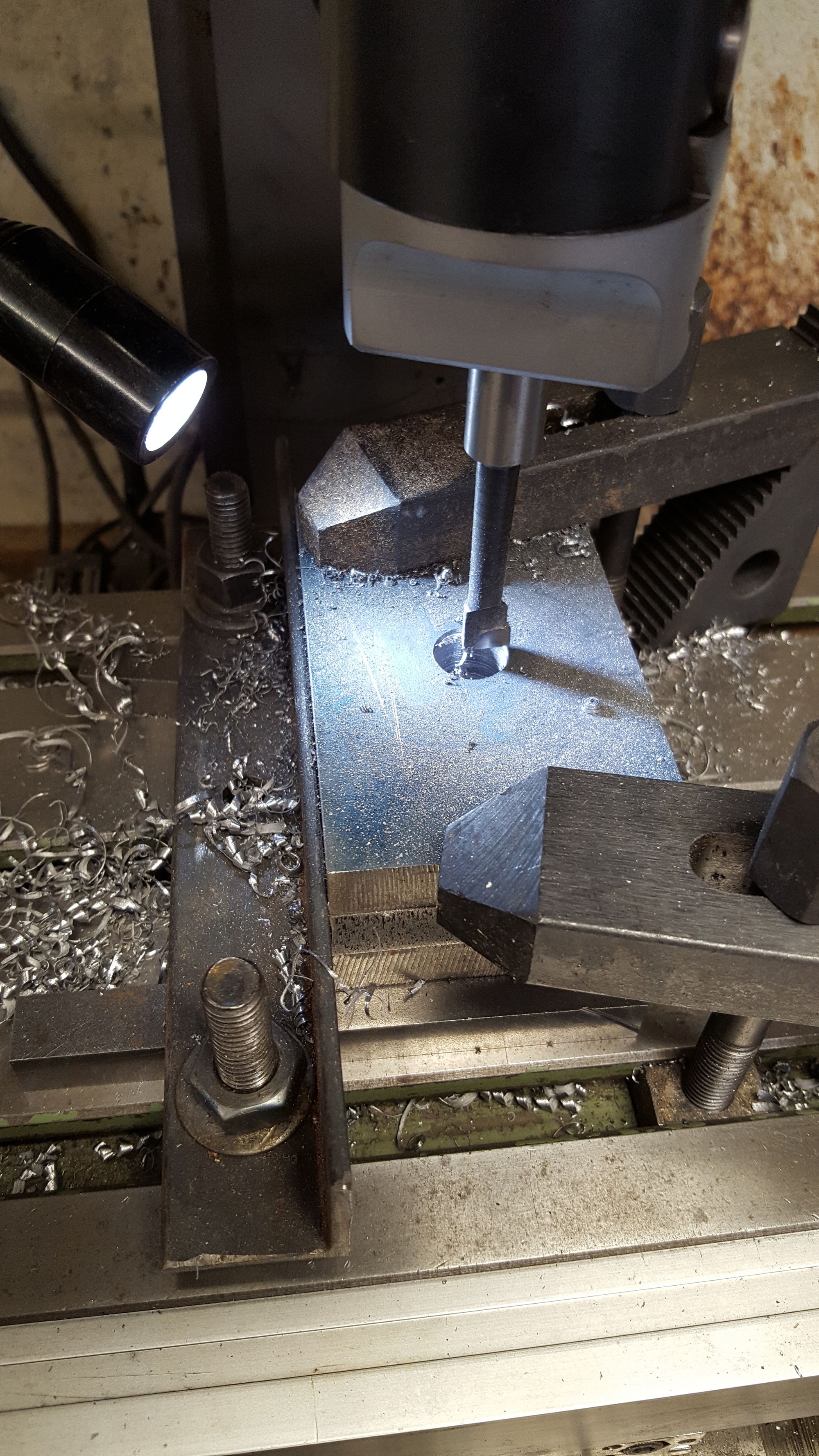
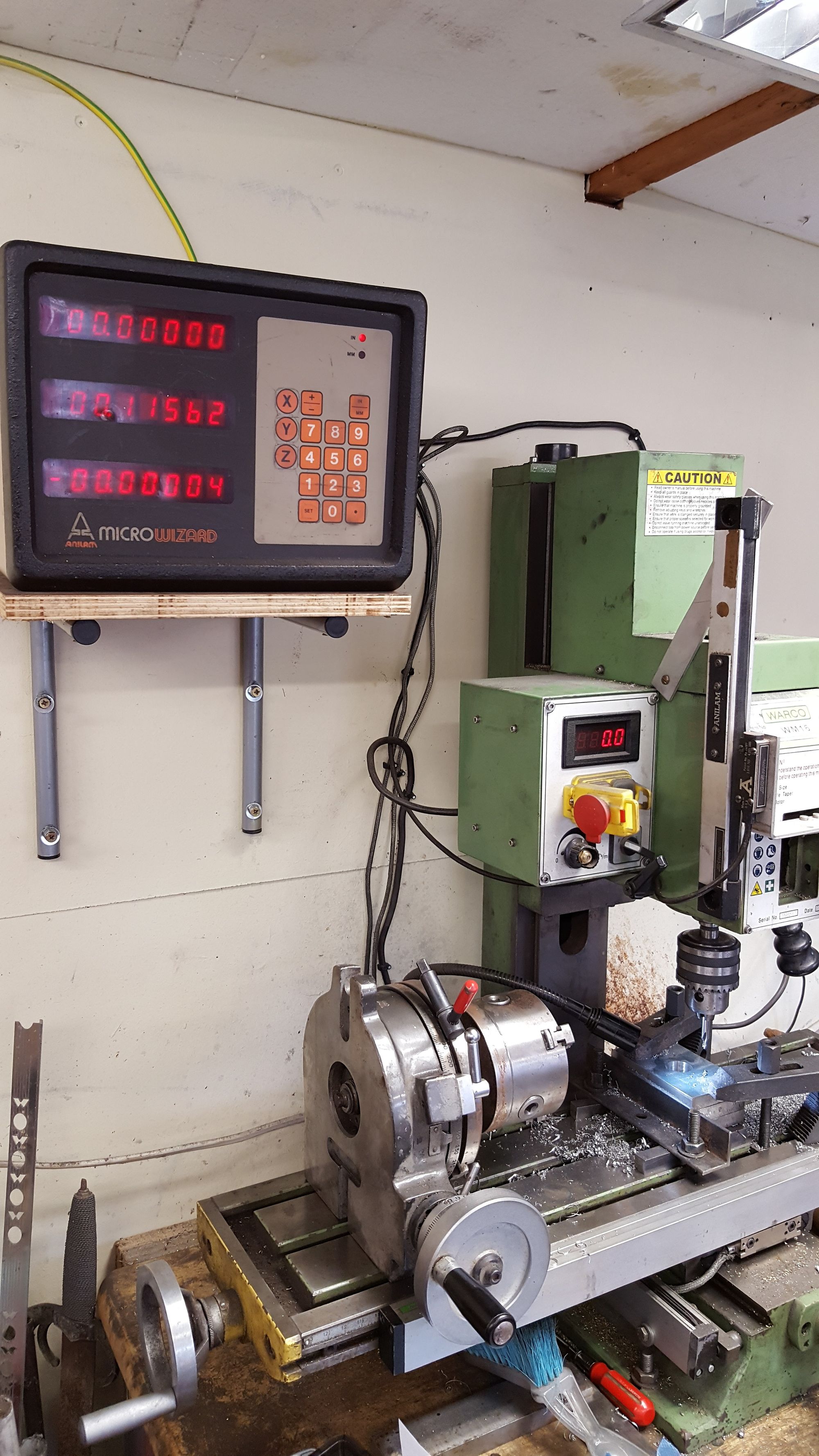
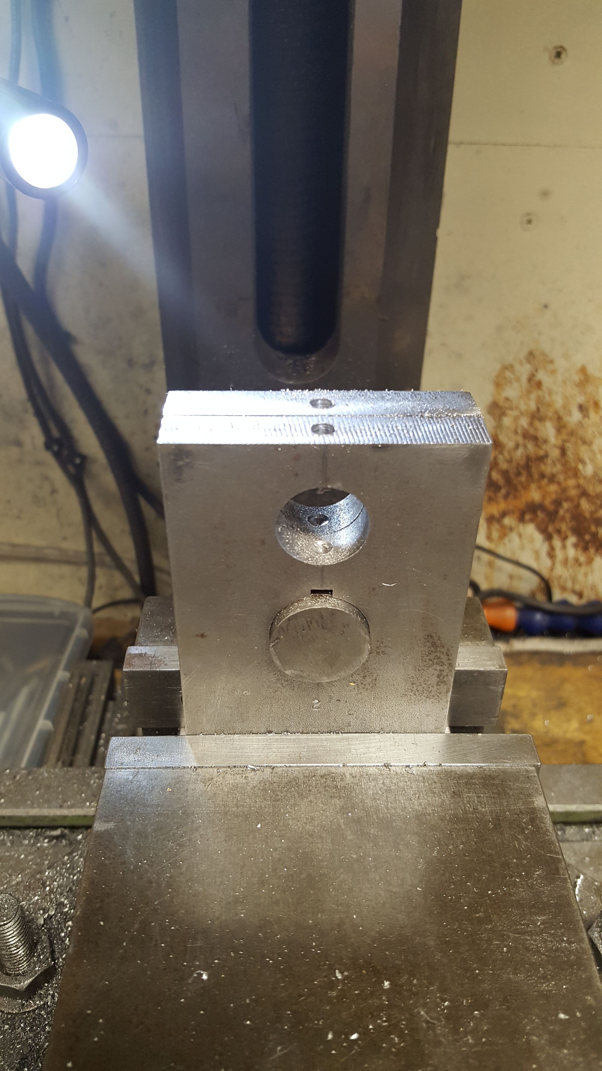
The crank webs require two different sized holes to be bored, on at 7/8th which is the one in line with the axle and the throw is 3/4", the critical distance between being 1 5/32 or 1.1562. Using the marked centre of the 7/8 bore I zero'd both X and Y axis and began step drilling up to around 490 thou, from that point onwards I used the boring head as can be seen here.
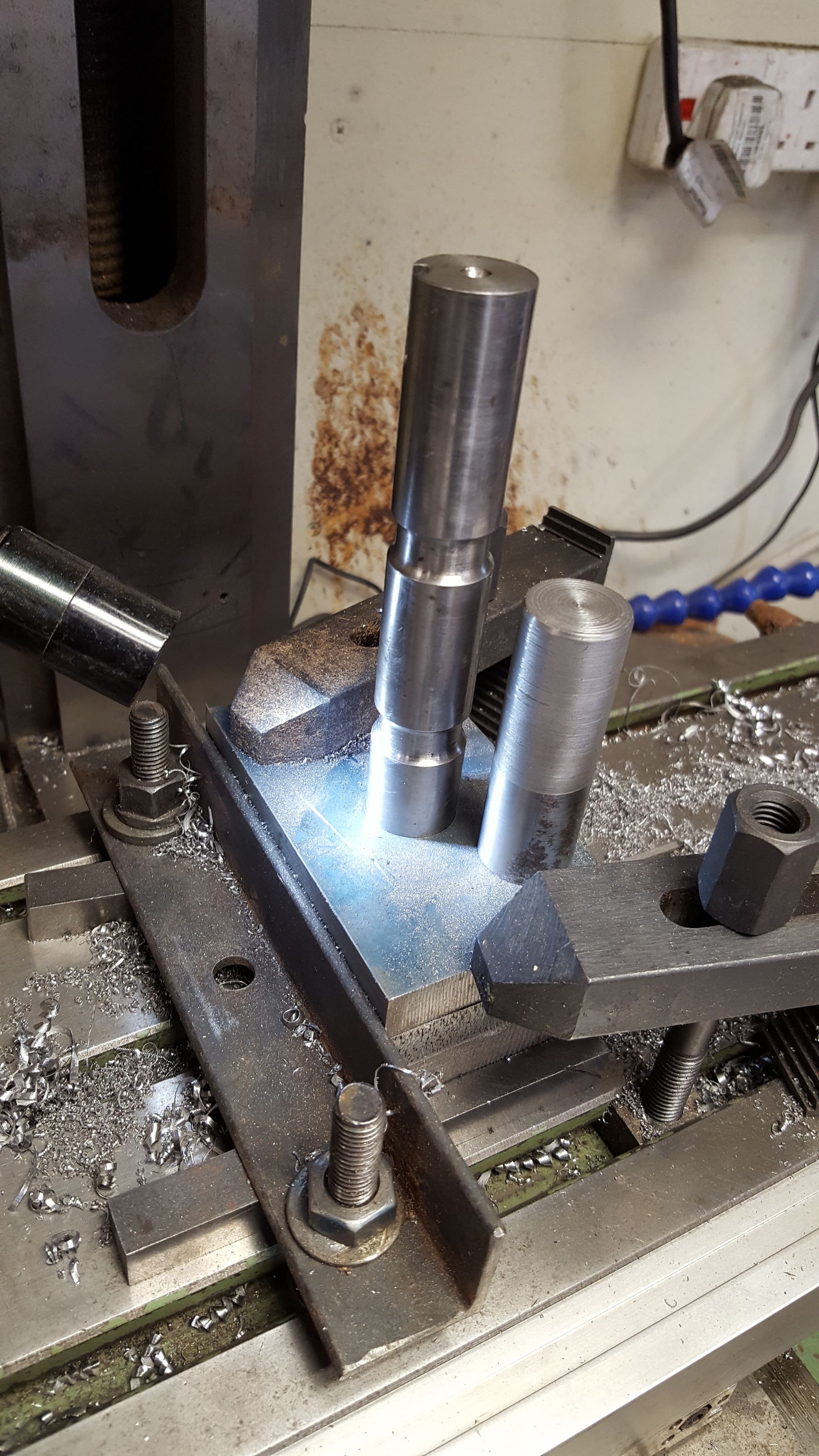
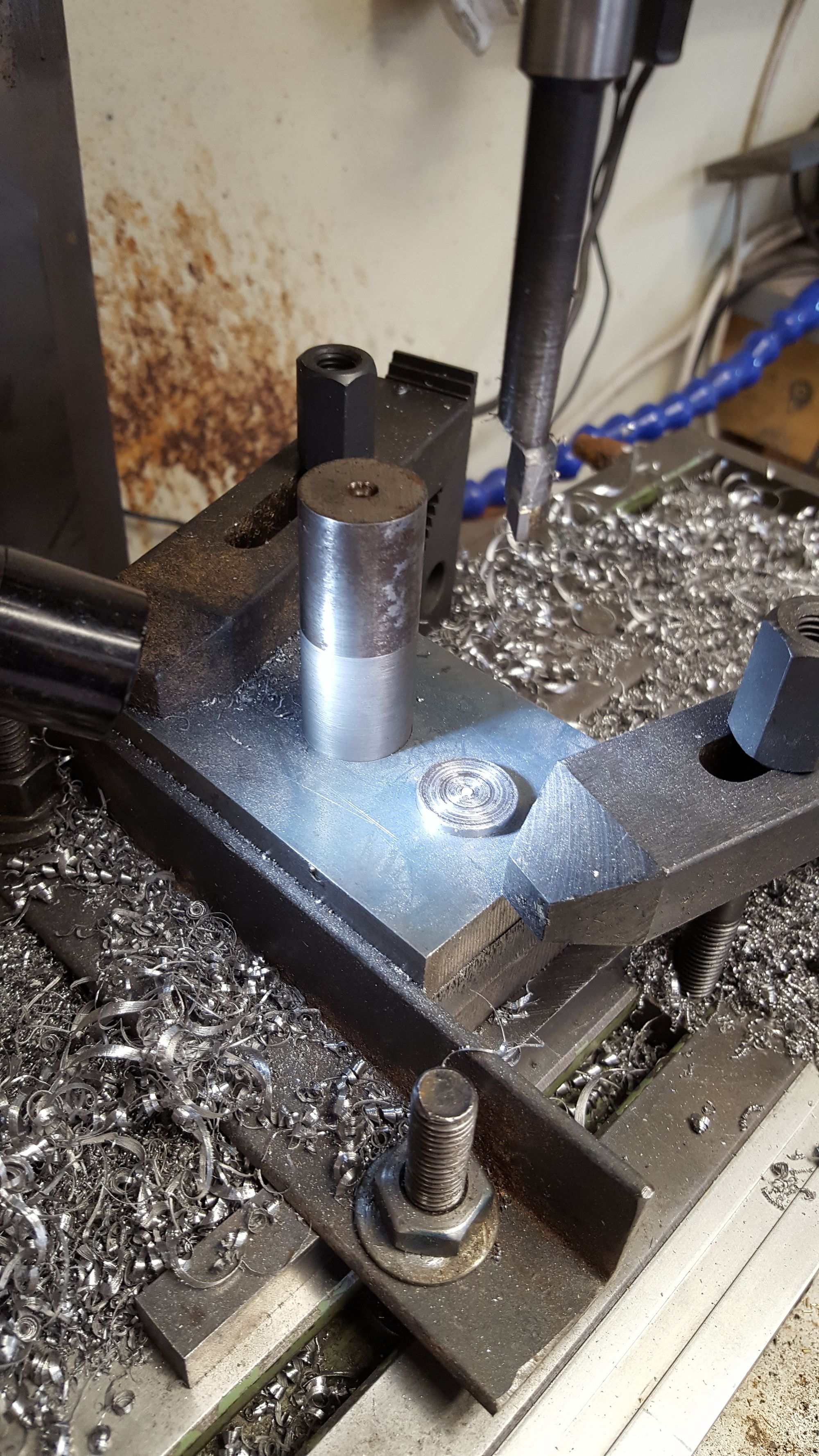
Before completing this first hole I turned up a plug slightly under the required size for the axle and chamfered the tip to use as a guide as to how far I was away from completion, I also did the same for the 3/4 throw pin to use next. Picture shows the 7/8 bore finished with the plug and the axle placed in it, something I regretted later as it took a bit of effort to remove the thing, at least I know the fit is good....
Y axis was then unlocked and moved 1.1562 ready for the 3/4 hole.
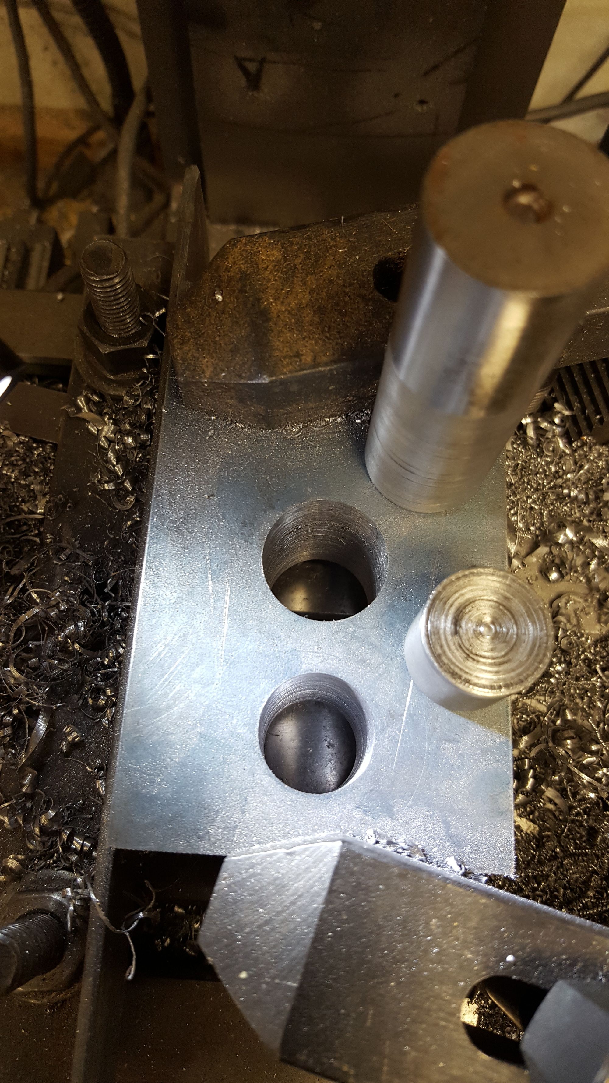
Second hole now finished with both plugs shown in situ, the holes are just shy of their required sizes, even though I plan to use loctite I wanted them a very close fit, not a press fit but they will require a little persuasion to locate fully.
And so the all important crank throw is done, I just need to get exactly the same with the crankpins to match....
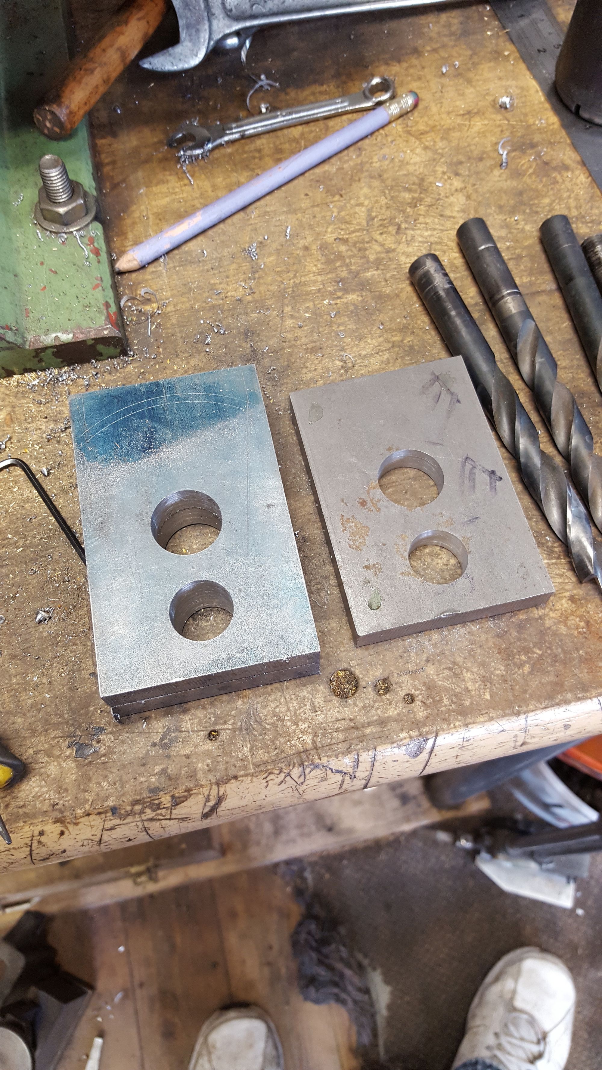
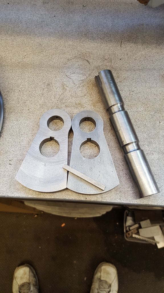
Last picture for this day shows the webs split from the jig plate requiring just a light tap on the jig plate with a hammer. The wheel crankpins are two different sizes, 9/16 for main drivers and 7/16 for the coupled wheels, I had considered doing them all 9/16 but will stick to the drawing. So I need to turn up two plugs to fit the 3/4 with spigots representing both sizes, these will be used to locate the jig to each wheel when broaching the keyways. It's all very well getting the axles quartered accurately but of no use at all if the broach's aren't all perfectly in line with the bore/crankpin holes.
I left the webs for now and moved on to the wheel crankpin holes.
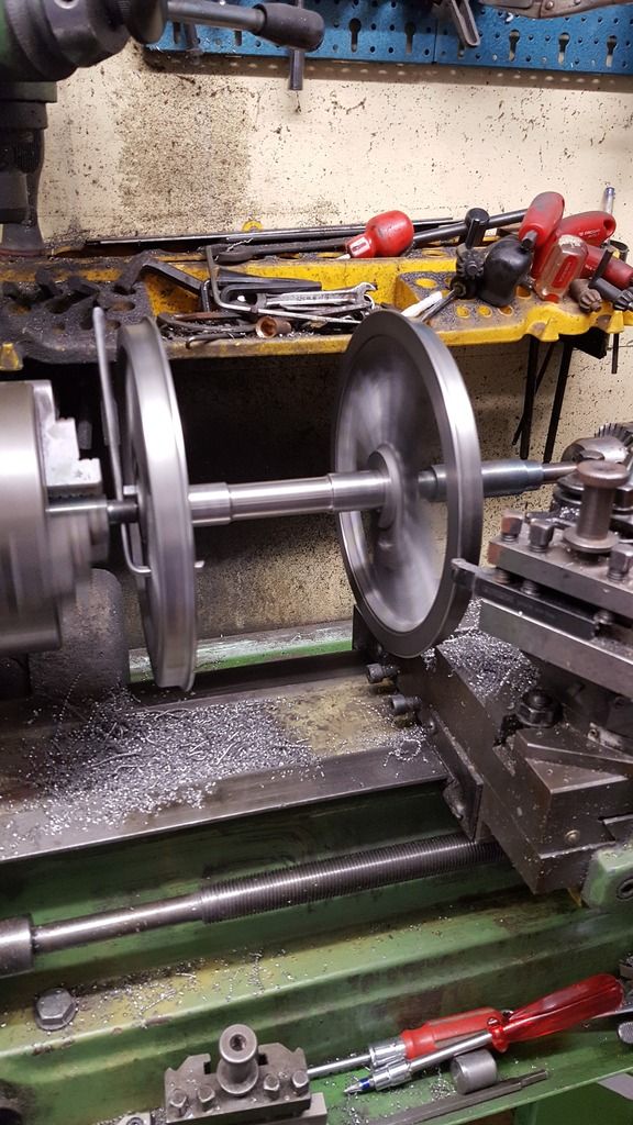
Back to the main wheels, in this case, machining the 9/16 crankpin holes for the main drivers. After a little thought on how best to hold the wheels so that each one could be set quickly and would be identical, I decided to use the faceplate that had been used previously for machining the wheels on the lathe. I also made use of the plug made for machining the 7/8 bore in the crank webs, just requiring the machining of one end to a spigot that fits the centre of the faceplate. Once these components had been assembled and fixed down to the mill bed and with the first driver in place I set 'dead centre' of the plug (now spigot) using the 'wobbler'. The spigot is a very tight fit in the wheel bore needing a bit of drifting to get the wheel on, this good fit should help with the accuracy while doing the crankpins, although it was tight the wheel could still be turned, if a little stiff.
First picture shows how the setup looks, the wheel is sitting on two lengths of 1/2 sq bar and was checked that it was sitting level.
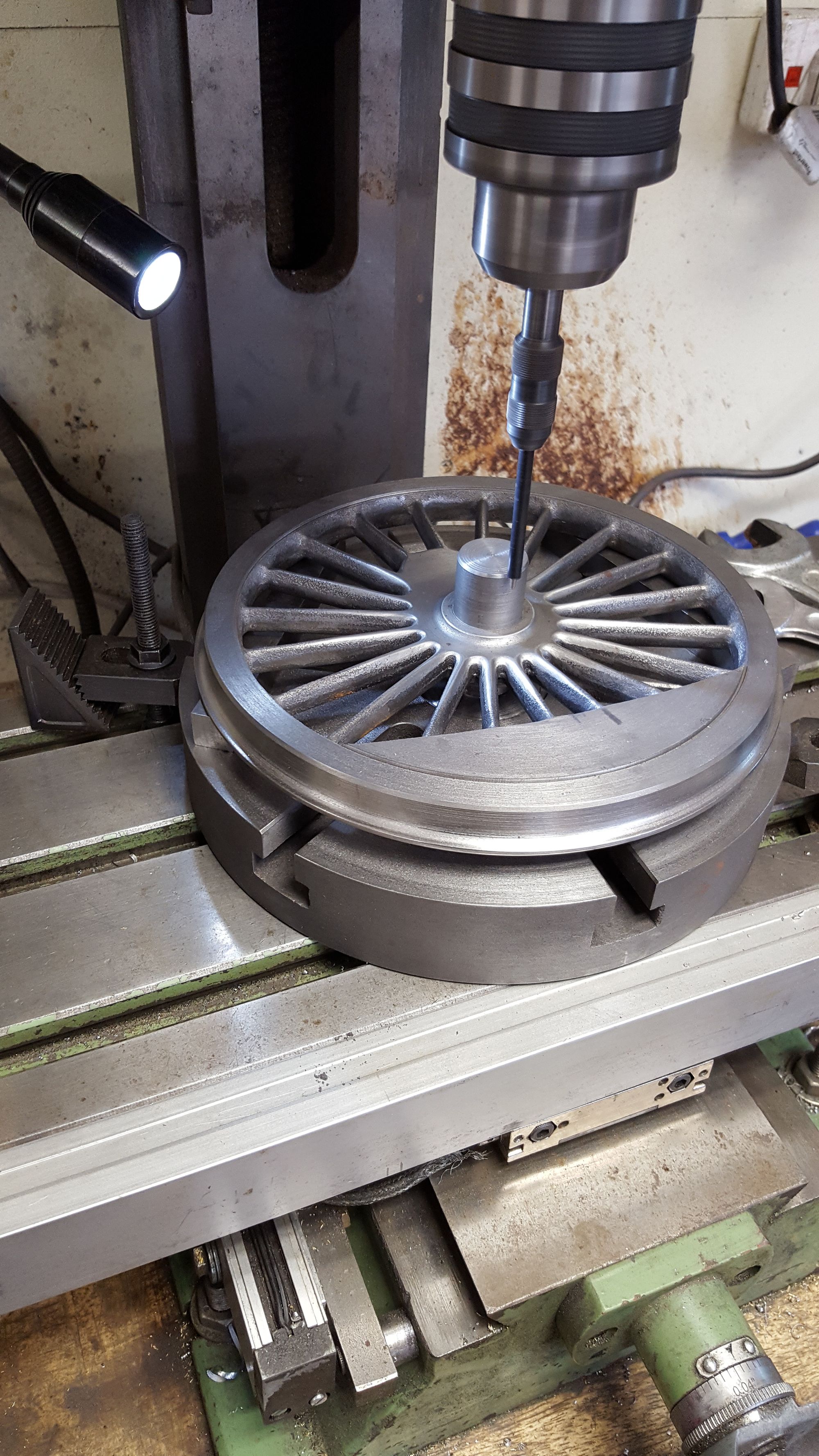
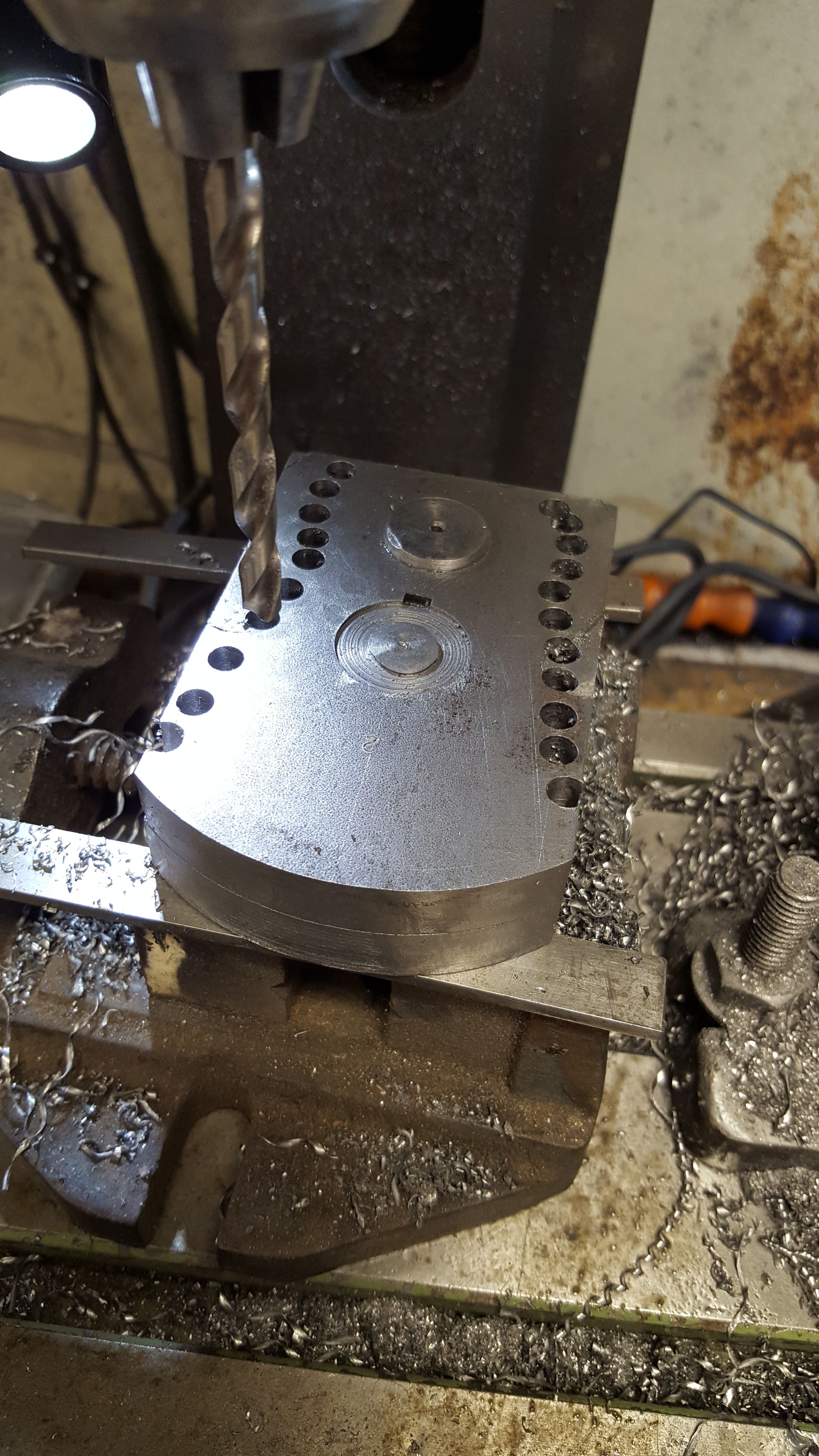
With dead centre set and before setting the drill to 1.1562 for doing the 9/16 crankpin I put a piece of round bar in the chuck, moved the head in to the spokes at their widest section and lowered down between the two centre spokes then bringing the bar back until it was touching the spokes both sides. This gave me my clocked position for the wheel on the spigot and was then clamped down. I only did this for the first wheel, then making a note of how the spokes looked in relation to the faceplate 'T's as I didn't want to keep moving the head once set to drill the crankpin bores. I did look at a few pictures of 4472's wheels before deciding on lining up with these spokes just to check that that is how they actually are, you can see in some that although the crankpin is lined up between these spokes the centre boss isn't always dead centre. so the spokes are what I have used for my datum.
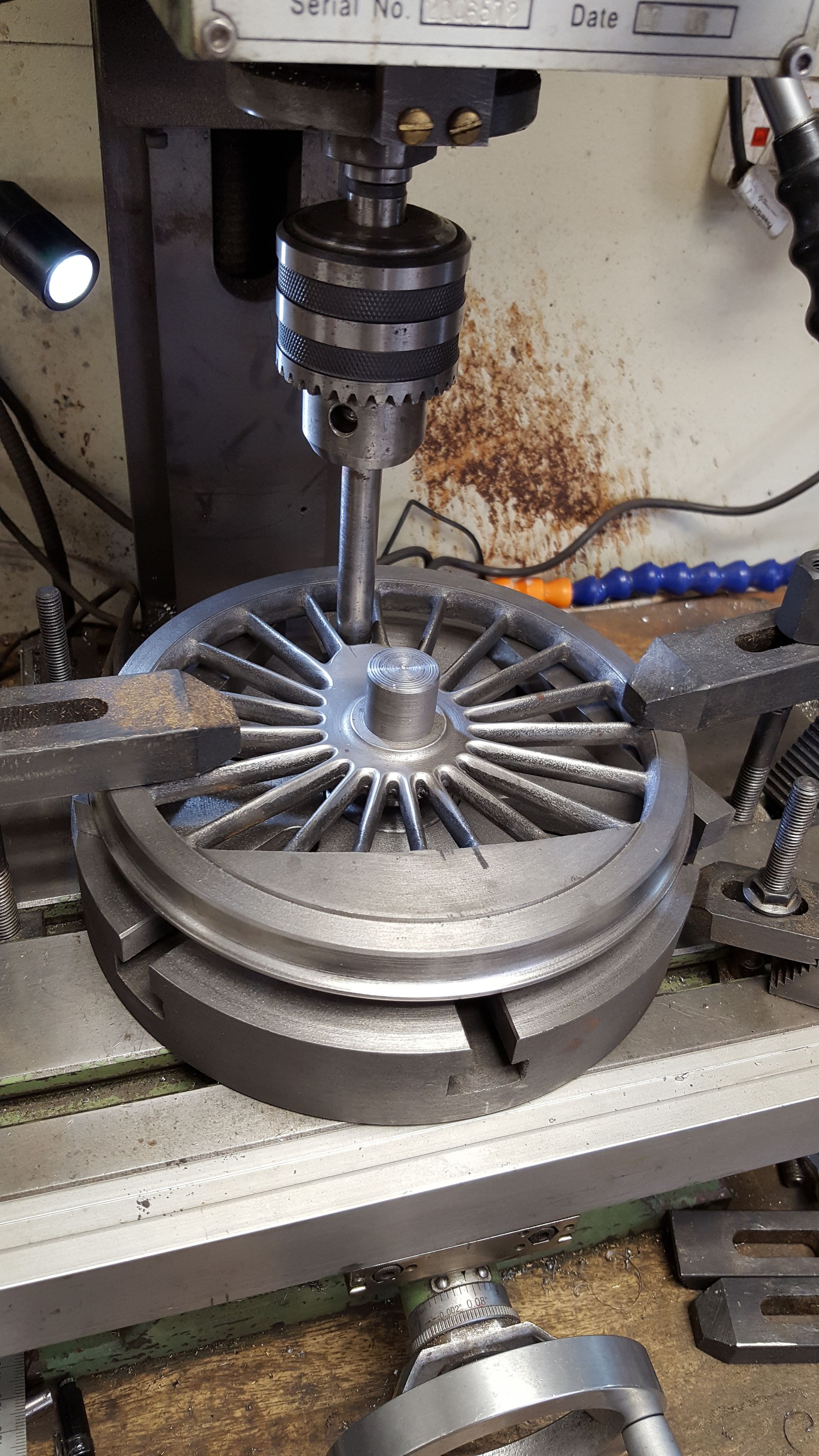
Next, the head was set at the required 1.1562 from dead centre and the drilling the began, centre drill, 5 step drills with the final cuts being done with the boring head.
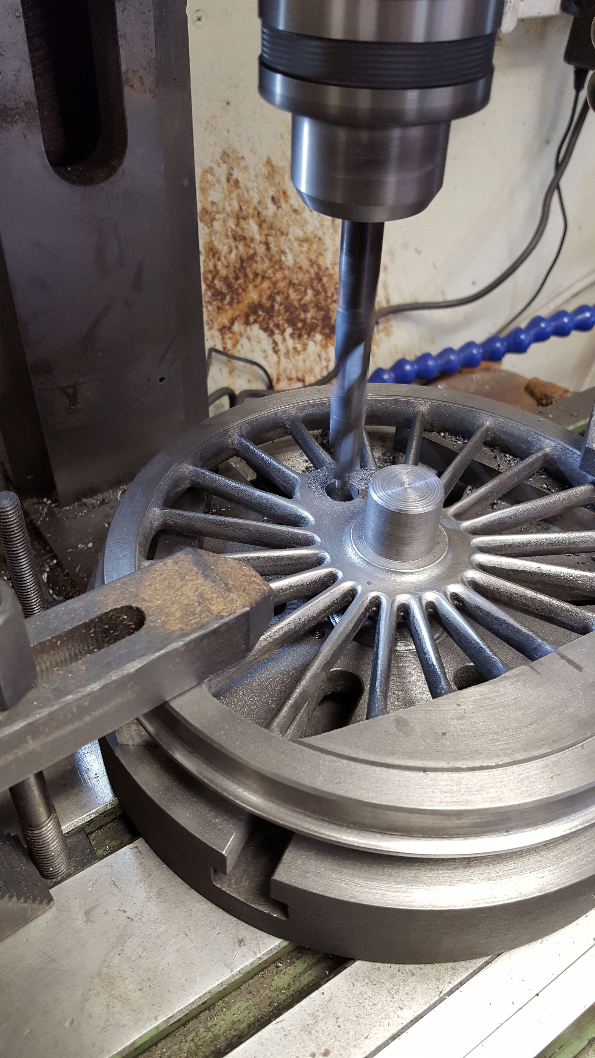
Hole was then finished with the reamer...
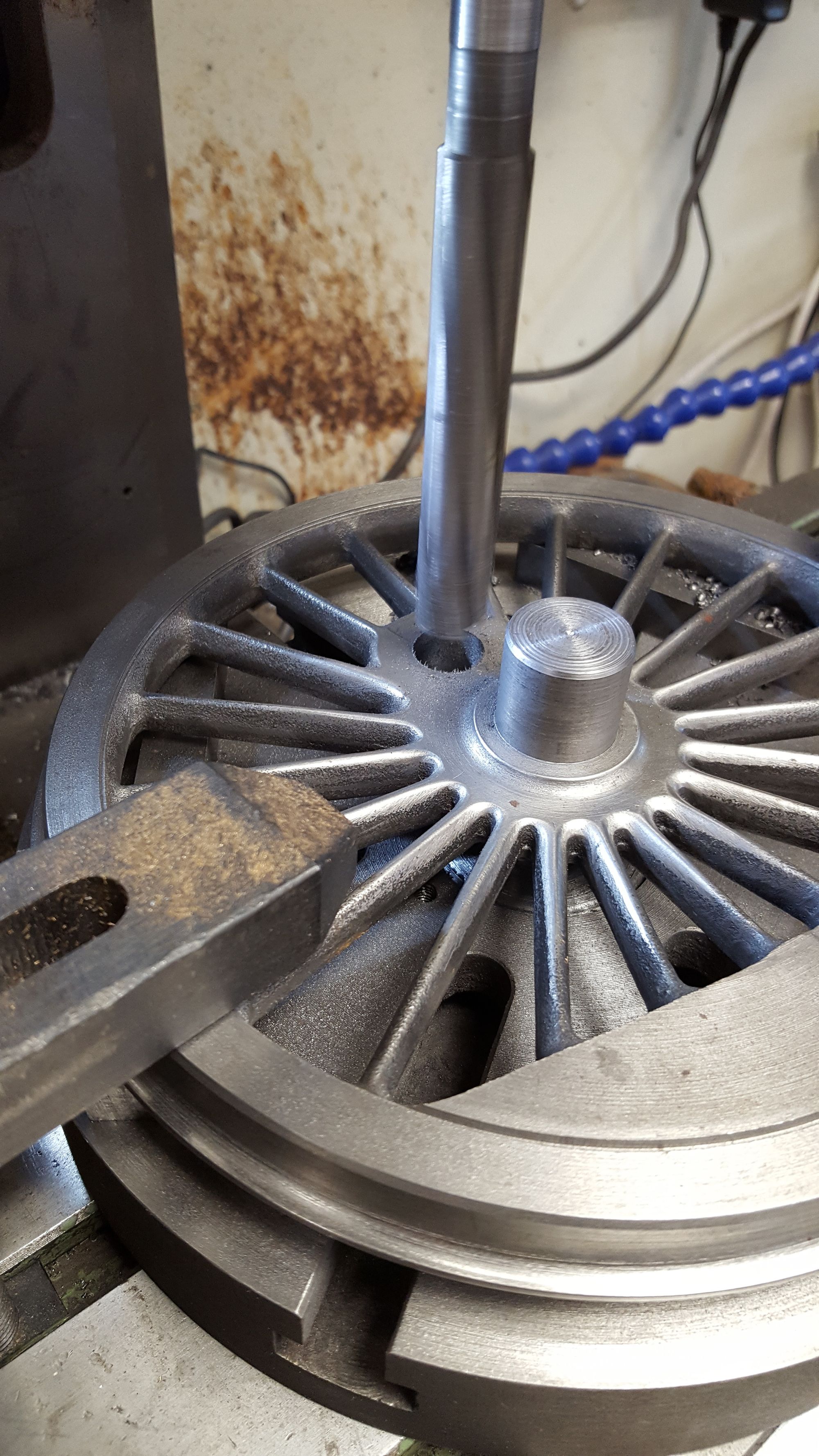
And so the two main drivers are done,...
Today was one of those days when after achieving what you had planned for the day you feel happy with the outcome, a definite case of 'sit back and relax' Now I haven't finished the wheels just yet but I only have one operation left to do and that's broaching them ready for fitting permanently to the axles. I've not decided yet how to approach this, I want the broach to be exactly on the centre line of the axle and crankpin, the jig will ensure that all are the same but I need to be sure of that centre line location to maintain that famous Gresley 6 beats in an even pattern. I'll give this some thought over the next few days while shaping the crank webs.
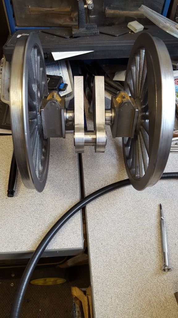
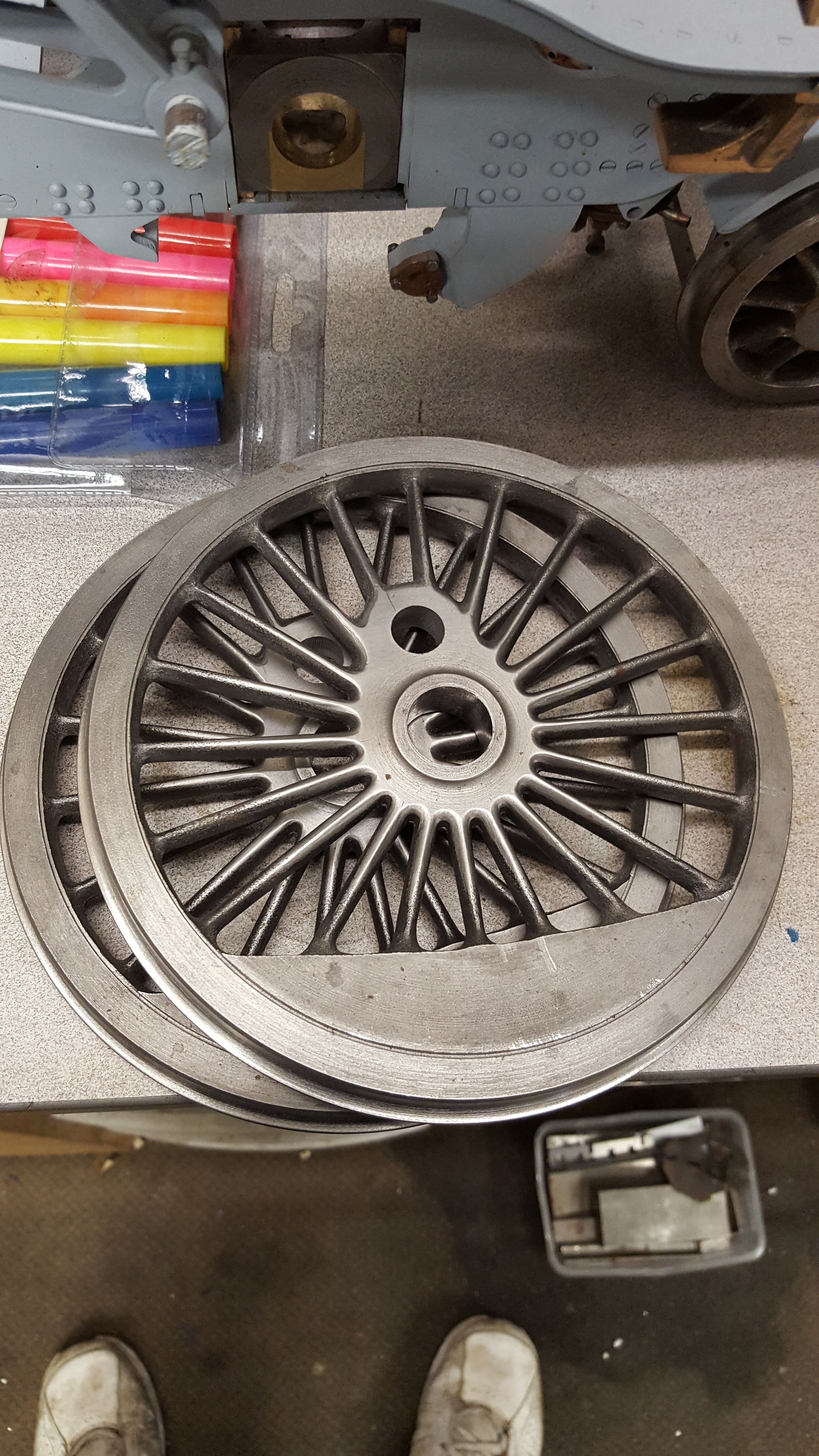
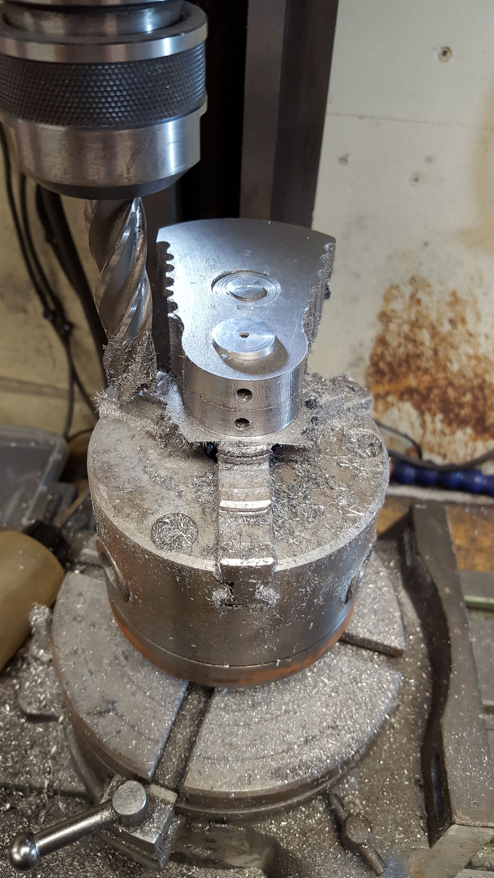
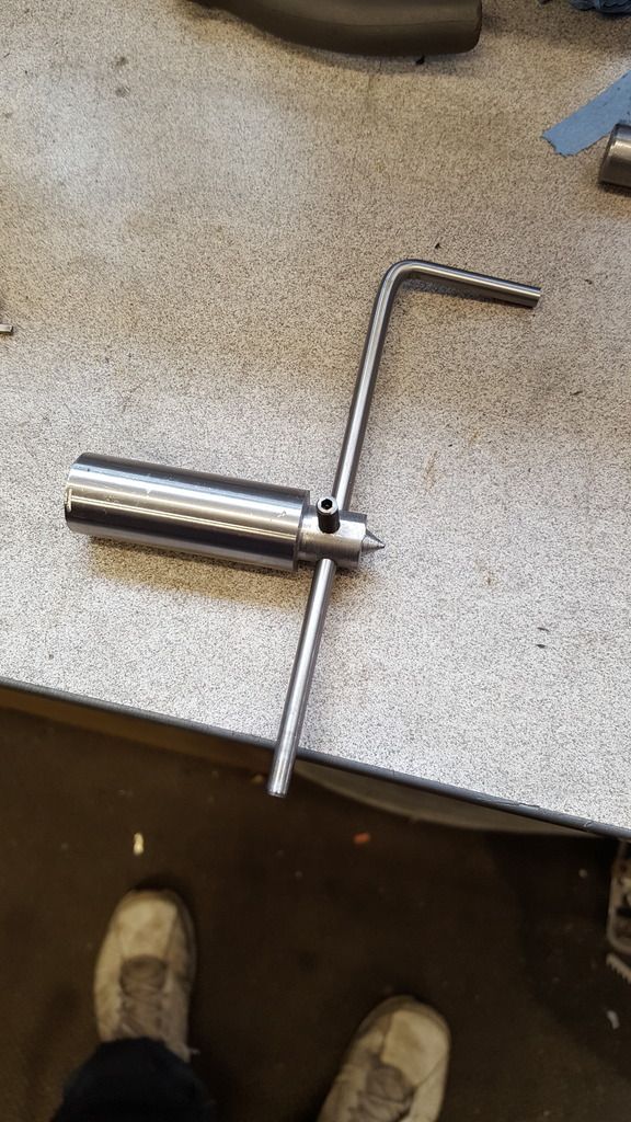
So after finishing drilling the crankpins it was time to check that all was well with what had been done over the last few days, it's great to have the DRO but you don't know the true reality of how well the various operations went until you can test them physically. Enter the crank Jig, yes this will be used for the broahing but it's also perfect for checking that the distance between axle to crankpin is correct. To do this I needed to turn up two plugs, one for the axle and the other (stepped) for the two crankpin sizes. Since the wheel bores are undersized to be a press fit on the axles I had to machine an extra very fine step in each plug.
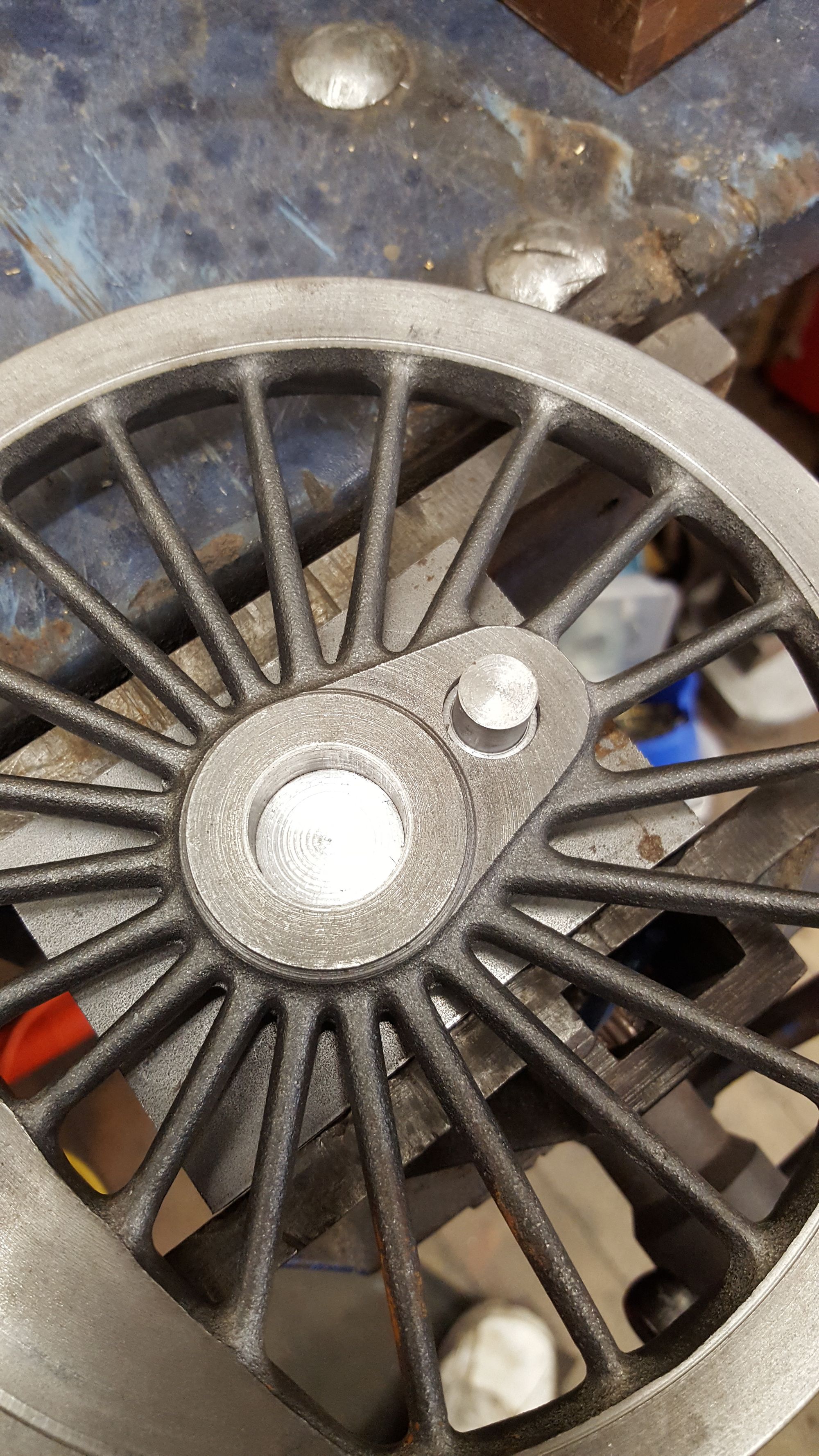
The first picture shows the jig being held in the vice with one of the main drivers fitted to check fit, note the step in the crank so that it can check the coupled wheels too.
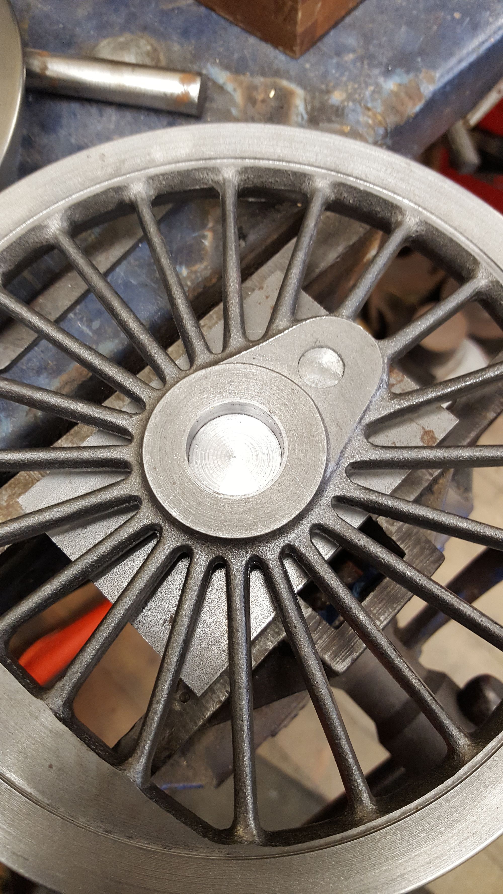
And now one of the coupled wheels, the fact that both types fit the jig perfectly and that the jig is identical to the crank has made me a very happy man, I can breathe easily for a while.
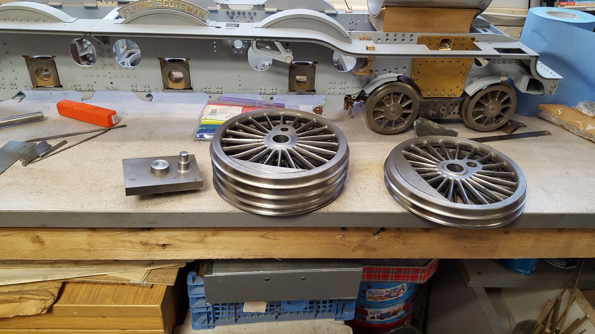
To finish, a picture of all 6 main wheels and the jig that proved they are good.
There's another thing that has made me happy today and that's the fixture of the bushes in the wheels, remember those?, these wheels have now been drift fitted countless times onto various plugs and there has been absolutely zero movement from any of the bushes and so that other possible worry, that had been festering in the back of my mind can now be put to rest......I may actually sleep easy tonight....
Broaching, I had hoped to include the broaching of the wheels in this update but will have to wait until I can borrow a larger fly press as mines too small in throat depth, it's also too small in height really too but I managed to get the crank webs done and thus the jig too, ready for doing the wheels. My son has arranged the use of such a press in a fabrication unit next door to his work, unfortunately, the owner is out on a job today but hopefully it won't be too long a wait.
Ok, so two pictures, first shows the jig/webs held together having already had the first pass of the broach awaiting final cut once the shim has been inserted. I took this relatively easy with short movements and plenty of cutting fluid
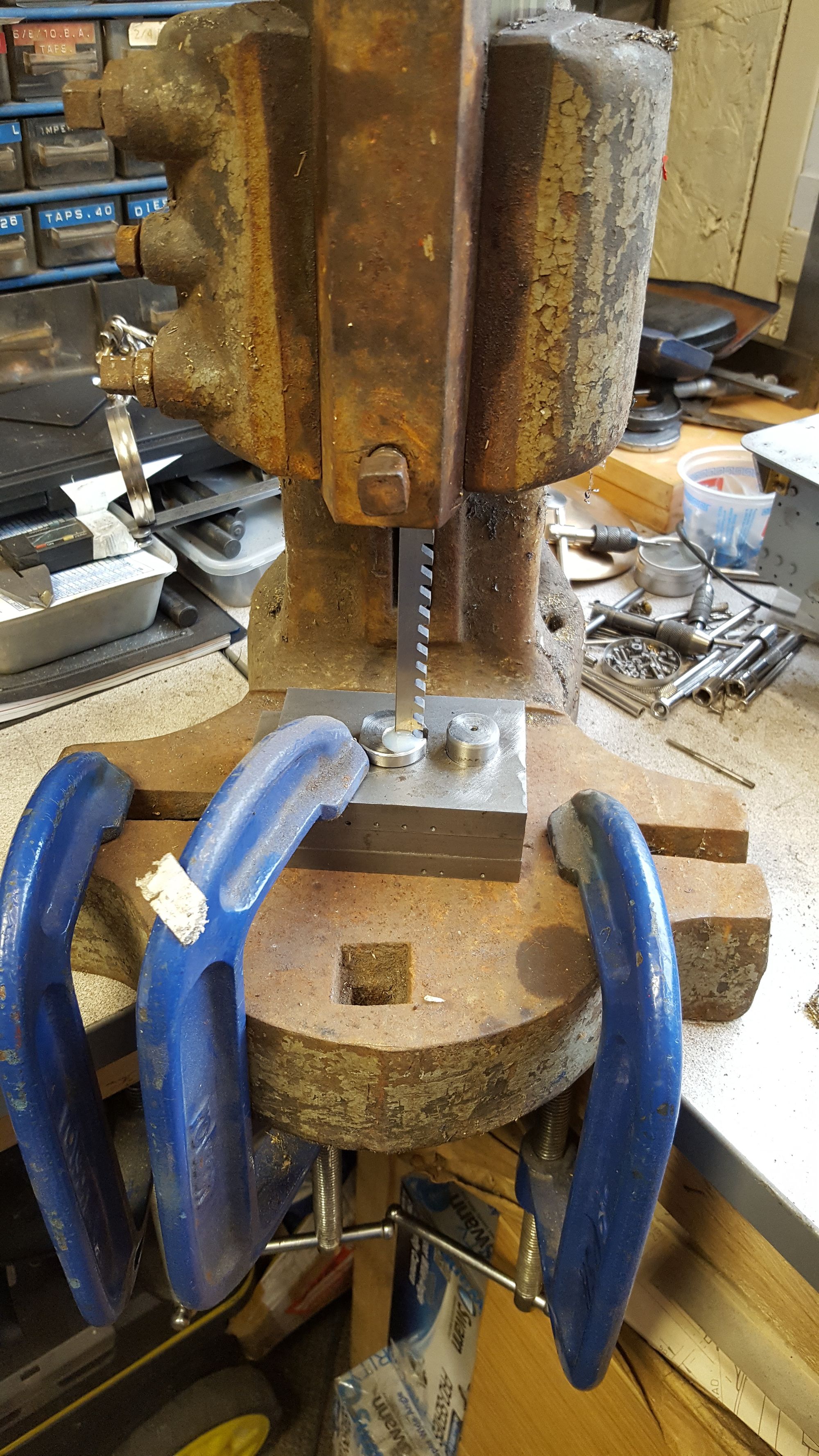
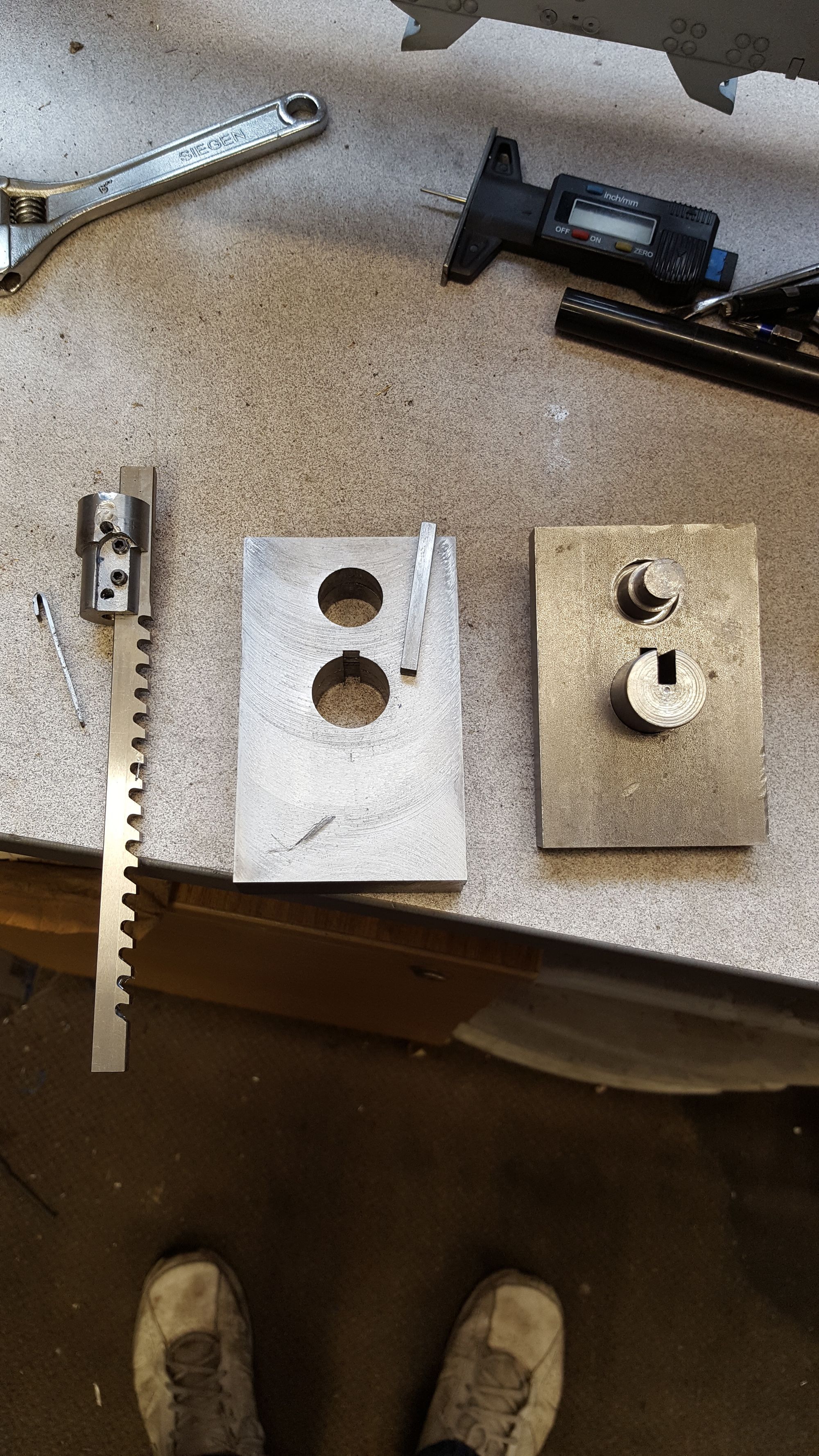
And the second picture showing the web blanks with their cut and also the bore jig which I have made ready for it's next use for doing the wheels, I made up the broach holding tool to fit my press, hopefully it will be of use on the borrowed press too, shim has been laid next to it just to show the components used. This is my first time with broaching so I'm happy to get it done, the wheels should be a bit easier being cast iron(+steel bush) instead of the tougher EN8. BTW the keyway size is 3/16.
Another good day today, well not that I have many bad days as such, but some involve a milestone moment and today is such a day.
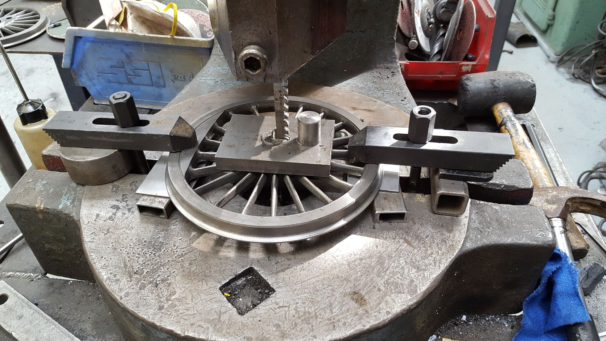
Whilst in the middle of machining the crank webs ( details after) my son called to say that the press was available for me to use, so I dropped everything, loaded the car and headed off. The press involved is a deep throat N0.4 fly press which was perfect for the job. It took a while to set up, made slight changes to the tool holder to fit and sorted out some steel + shim to set the wheels level with support on both the rim and boss. I only took one picture as I was aware of the time that I was taking in someone else's commercial workshop and wanted to get the job done as soon as possible while not rushing anything. This picture is of the second wheel and it's just had it's final cut ( as can be seen by the shim in situ).
And here we have all 6 drivers safely broached, I had one bush move a little, about 1mm, didn't effect the operation as I just tapped it back home. None have sprung which is good and testimony to the quality of the cold drawn steel tube chosen for the job. I will double check that all bushes are secure before fitting the wheels to axles although since they are a press fit I don't expect anything to move. The plan is to turn up some end caps to fit over the axle end that will stop the wheel being pushed on too far, a possibility due Don's design not having stepped wheel seats but not a problem if approached with this in mind. Also in the picture are the other parts required for assembly, all except two...the crank webs.
And so the crank webs, first job was to drill the holes for the pins , the 3/4 pin is a very tight press fit but I wanted to be extra sure and so will pin then too..belts and braces....pinned/key'd, pressed and bonded...think that should do it...
BTW I have slightly increased the diameter of the small radius to give a bit more meat to it due to the holes drilled, again, belts and braces .
Here I have machined the large radius and have now begun chain drilling the rest before hacksawing the excess material away.
Lastly, the small radius machined leaving just the straight angled cuts to finish, this is where I had got to when I left everything to broach the wheels, so no final picture for the crank webs yet, all being well I may get these done over the next few days.
Moving on with the crank I have now got to the assembly although there are still a couple of things to do to complete, I'll tell all at the end...
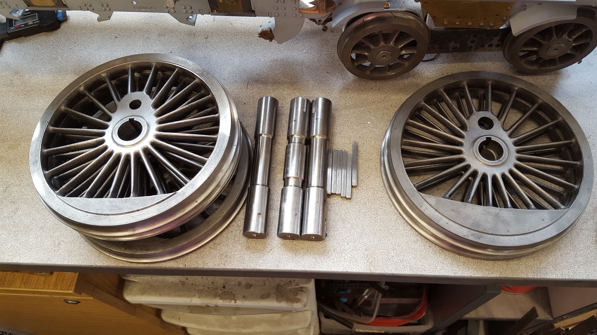
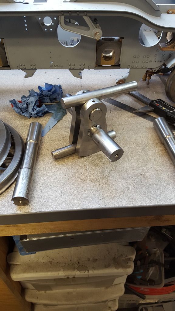
At last, I have all of the parts required to assemble the crank, if I have to make another of these one day I may be tempted to machine it all up from a solid lump, may be very wasteful but may actually be quicker, anyway it's done now and here are the parts to show...
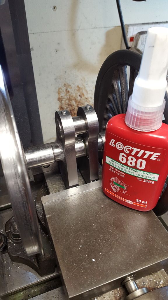
Now my method of assembly was this, I first joined the two webs with the 3/4" pin (overlength) and spaced them at 9/16 using some bar of that diameter( alas I don't own a set of slip gauges...yet) these parts are a press fit and I have used loctite 640 to ensure a solid joint. This gave me plenty of time to then fit the axle and key as it has a slow cure time. For the axle I have used Loctite 680 which cures in 10 mins. The reason for two different Loctite,s is because of the axle not being such a close fit as the crank pin, it's still a very good fight but needed to be more of a sliding fit than pressed so that I could get the two webs onto the axle after they had already been fitted to the pin, last thing I wanted was to put any undue stress on any of the joints before they had fully cured (24hr).
Picture shows the assembled crank and the two bars used to space the webs with their correct gap, the other thing that I needed to be aware of during assembly was to ensure that the webs were in the centre of the axle.
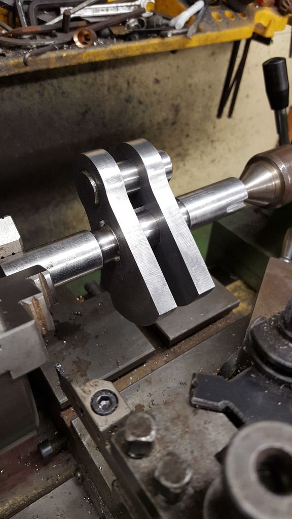
To check that all was as good as it looked I spun it up in the lathe. Once fully cured I will drill and pin the crank pin and machine off the excess pin length. the center axle section won't be removed until after the wheels have been pressed on.
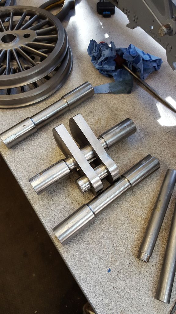
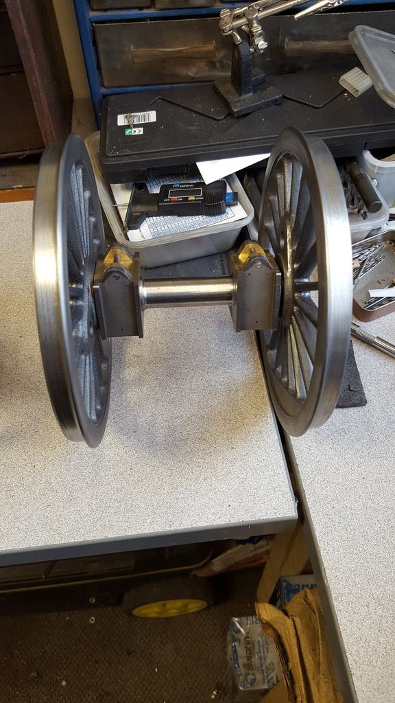
Last picture just to show the three axles together, the crank is quite a lump, tomorrow I'll finish the crank and prepare the key material ready for fitting the wheels which I hope to get done before the weekend...can't wait...
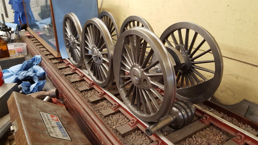
I took this picture last night...just couldn't resist it...I wasn't going to post it until I had finished machining the wheels between centre's...here is where I came across a problem, that being my lathe capacity...I have swing, length and just about enough depth, what I hadn't considered was reaching the assembly over the cross slide. Not possible using the live centre which would be my preferred choice, so I've had to put the thinking cap on which I'll cover in more detail later once I have finished...hopefully successfully....I have the method and am in the process of machining up two beefy dead centre's which right now are cooling after having their tips hardened...no dogs for this lathe either so that has been incorporated into one of the dead centre's.. oh the joys of model engineering....
The picture made me happy, though....
Here all 3 sets have been machined to overall diameter of 7.406 . The setup between centre's seems to be working well. Here's a taster of what I've been up to this morning....as well as finishing to diameter I have also finished the back radius at 3/32.
No i don't have a rolling chassis yet but I'm close, very close.
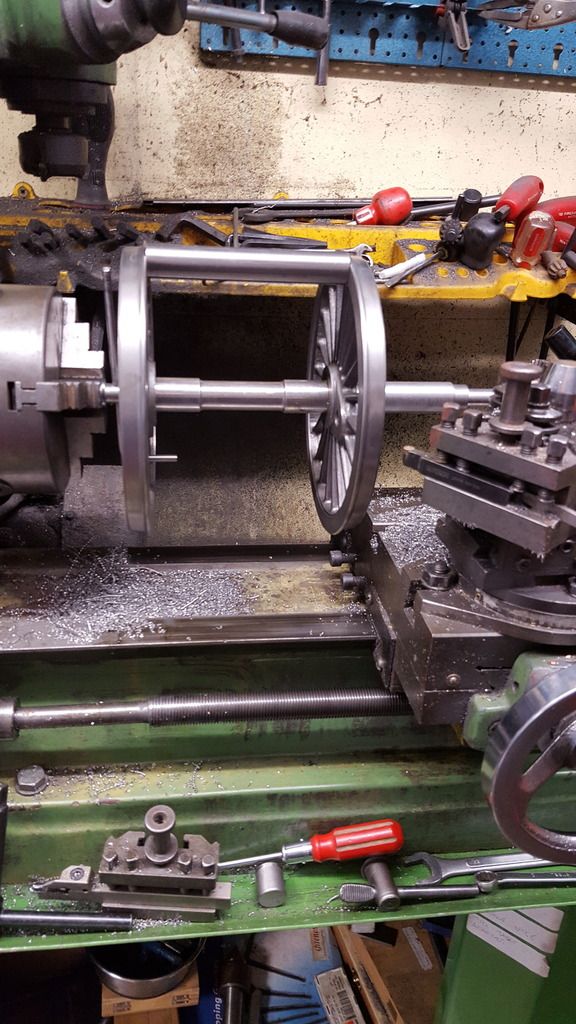
As mentioned last time I have had to turn up some 'dead centre's' so that I could machine the wheel assembly's which are too big to be able to use the live centre, it just doesn't have the reach. One centre was just plain turning and you'll be able to see it in the pictures but I also needed a way to turn the assembly (no dog's here) and so made one to include a dog for driving the wheels. Picture shows the shorter of the dead centre's with Dog that sit's in the chuck end. Material is 3/4" silver steel, the step is for clearance from the keys still sticking out of the wheels and the tip is angled to match the centre holes in the axles, 60 degrees IIRC. The step was cross drilled for some 3/16 silver steel and then another hole drilled at 90 degrees to that which was then tapped 2 BA with a grub screw to hold the bar in place for turning. hope that makes sense...picture was taken before the tip was hardened.
Each assembly was first checked for the correct 'back to back' dimension of 4 11/16 using a length of silver steel that I turned up for the job, as it turned out the crank assembly was a little tight which I'll take care of later by taking a couple of thou off the inner tyre face.
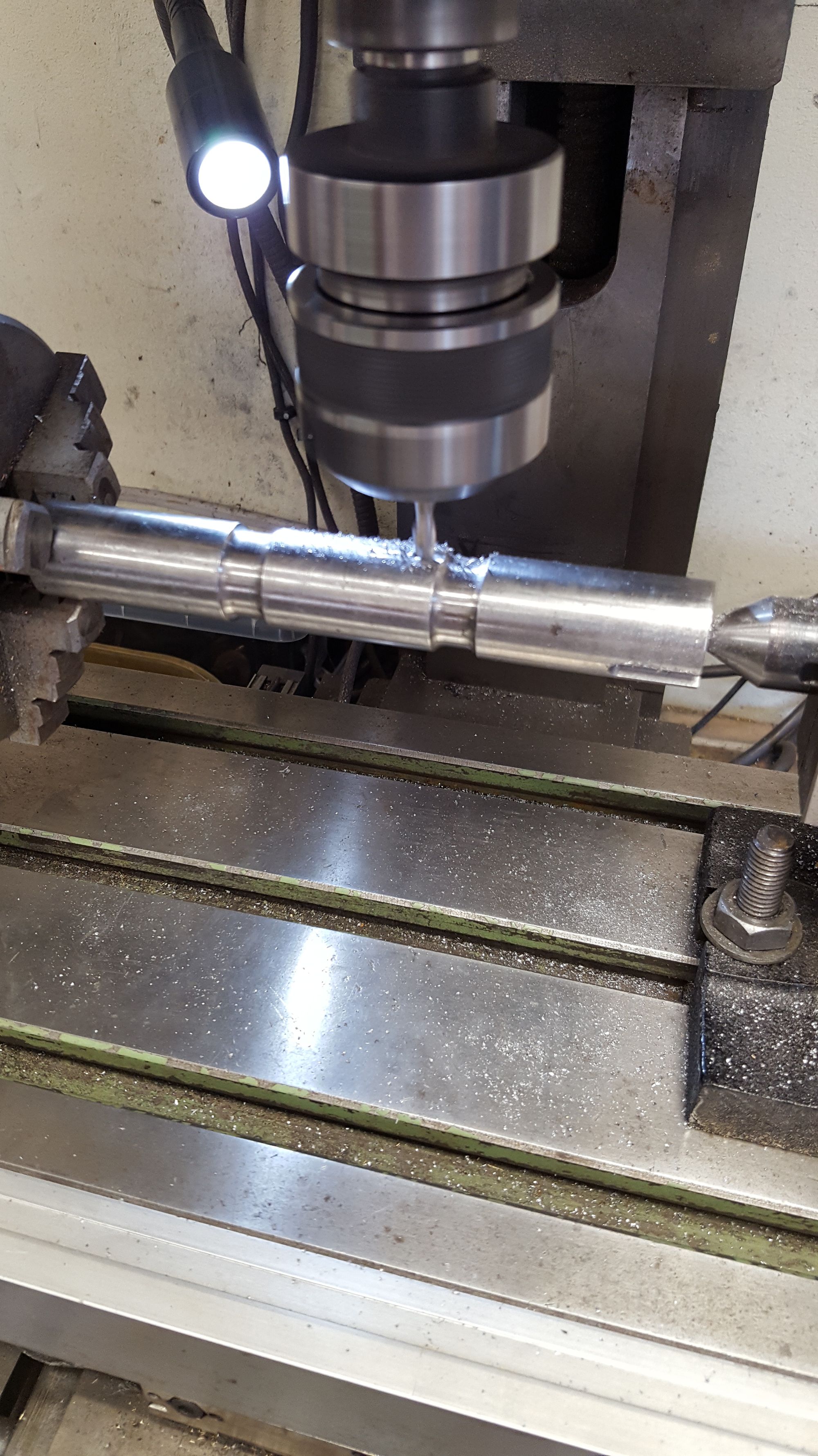
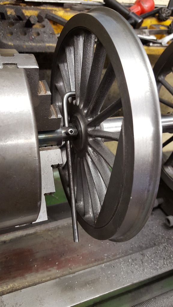
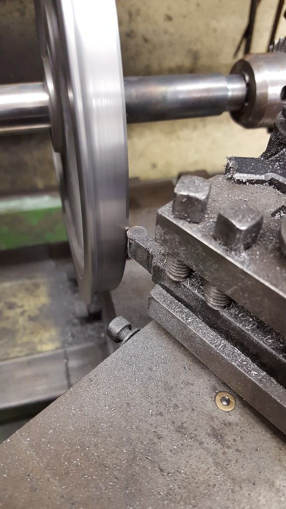
The next stages were pretty time consuming, the wheels had already been machined close to size just leaving a little material to true things now that they are fitted to the axles, in this next picture I'm doing the final cut for the flange diameter which is 7.406, I only needed to take a couple of thou off for this first stage of final machining. I did the rest in the following order, rear radius, tread, chamfer leaving just the removal of the protruding keys to deal with. For the tread I used a 6 mm profile insert set at 3 degrees on the topslide and finished the 3/32 rad root with a round file by hand. It's not easy measuring the root rad but I'm confident that it's at the correct size of 7.093, the important thing is that with all wheels being machined in turn at the same dial setting for each job they are all identical.

A close up showing the dog, note that there's no chamfer here even though I hand machined it before, this is because when I first machined the wheels I wrongly cut the tread at 2 degrees, only when re-checking the GL5 profile did I notice my error...no big deal as it just meant a little more material to take off, I could still do this in one cut which is what's important to ensure all wheels were the same.
Chamfer being recut at 30 degrees by 1/16" depth.
With all of the assemblies machined to size (crank not finished) I decided it was time for the axles to meet their split boxes, I'm very happy with the boxes, the keeps are very tight and yet the pins come out easily, i'd forgotten how good these things came out...picture shows leading axle ready for fitting.
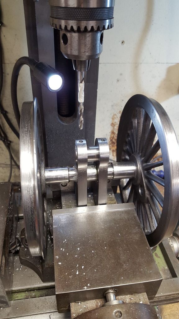
I then turned my attention back to the crank and fitted the pins to secure the 3/4 crank pin, these are probably a little overkill, especially when I consider that I machined the webs small radius while they were held just with the press fit of the 3/4 pin. The pin is now bonded too but in my minds eye this is the weak point of the whole crank assembly and I wanted to play safe, so two 3/16 silver steel pins that go straight through the pin into the other side were bonded in place, picture shows the crank held in the machine vice for drilling of the pin.
And here the pins have been fitted with the retainer used for reference.
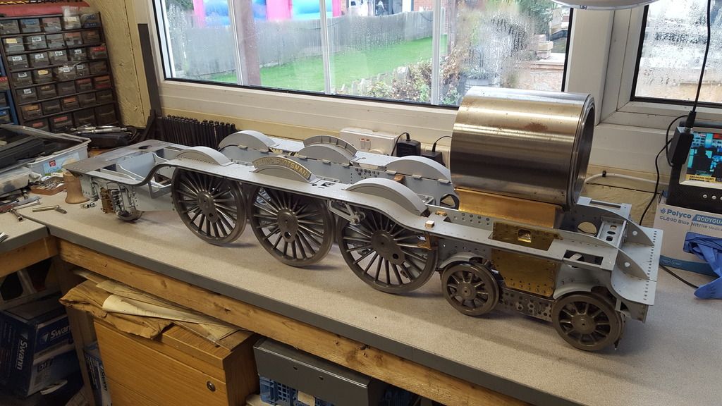
Ok, well today I reached that big milestone of having a full rolling chassis, well full as in all of the wheels fitted, still have a lot to do in regards to the springing/shock absorbers on the main drivers but it's very nice to see her standing on her own feet for the first time.
First job of the day was to finish the crank, although I was confident that it would be ok, I was still very apprehensive about removing the centre section of the axle, well after all it is the first crankshaft that I've built...
I decided to take it very easy and cut through the axle close to the webs, for this I held the assembly in the machine vice and used a strip of steel to protect the journal from any possible slip with the saw. Photo shows this, prior to this I did reset the assembly back on the lathe to remove a little from the back tyre face so that the gap was exactly 4 11/16, it was a little tight as mentioned earlier.
Next, I machined off the excess using a 12 mm long series cutter, this still didn't reach deep enough so I finished the last part with the trusty hand file.
And so we have the finished crank with it's axle boxes fitted to the journals ready for fitting to the chassis.

Here we have the three axles fitted ready for the big lift to turn it over, I had to get help for that one....

Finally, the loco is upright, this is at a weight now that's impossible for me to lift, I can lift one end but not both so need to give some thought to building a stand but I don't think I'll use a rotisserie type. These frames are very long and I'm not keen on having them hanging being suspended only at either end, guess I'll need to give this some thought.
NB: I took taken a short video of the chassis rolling, with no springing fitted to the main drivers yet I had to load the chassis down with weights to get the wheels to turn, some may remember that the cartazzi springs are possible too strong but had been left until more weight was on the chassis.
The video can be found in the 'Video's' section.