
So...Coupled Wheels
NB: I will state from the beginning that I had a 'whoops' moment with these, soon corrected, never say die is my way of living..:) more details down the page.
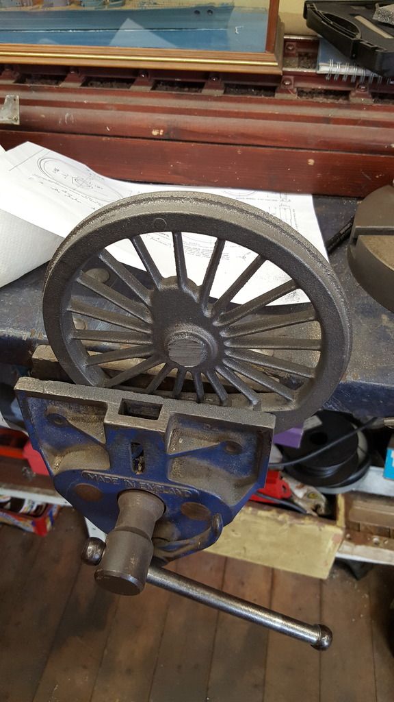
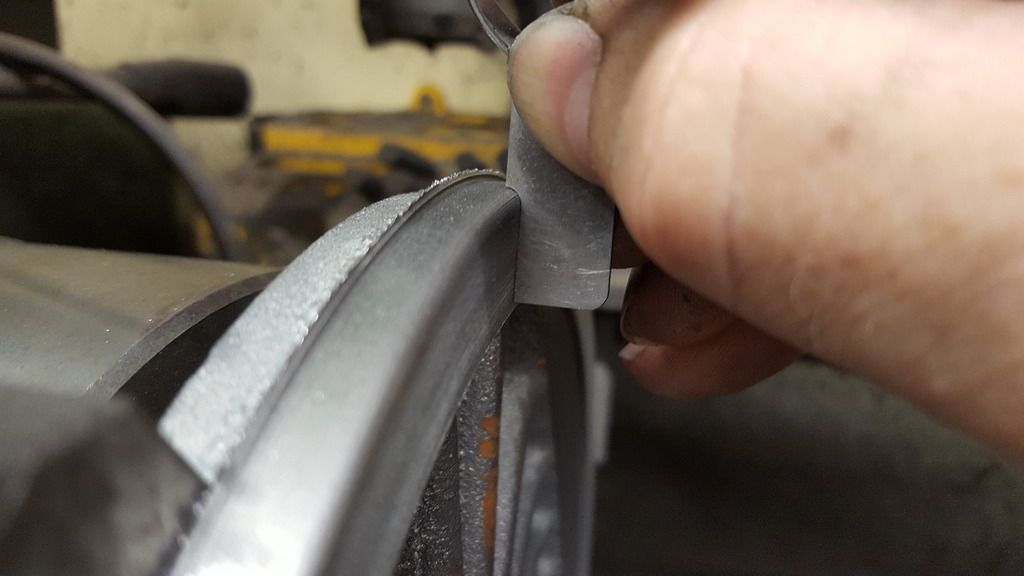
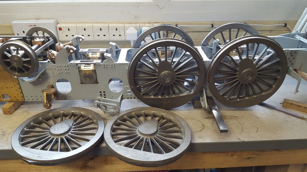
Don's castings are very good, very little flash and pretty concentric which is a good start. As those of you with experience in this field will know there's are a lot of things to take into account when machining wheels, more so with main drivers. I decided to first get rid of the excess metal in the flash and stubs, a hacksaw sorted this out as seen in the first picture.
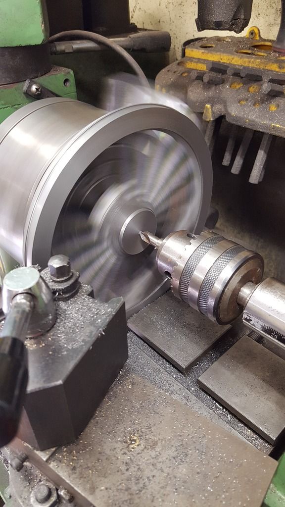
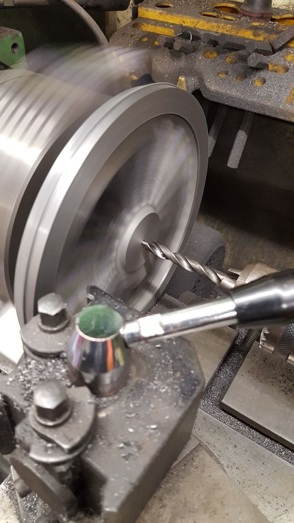
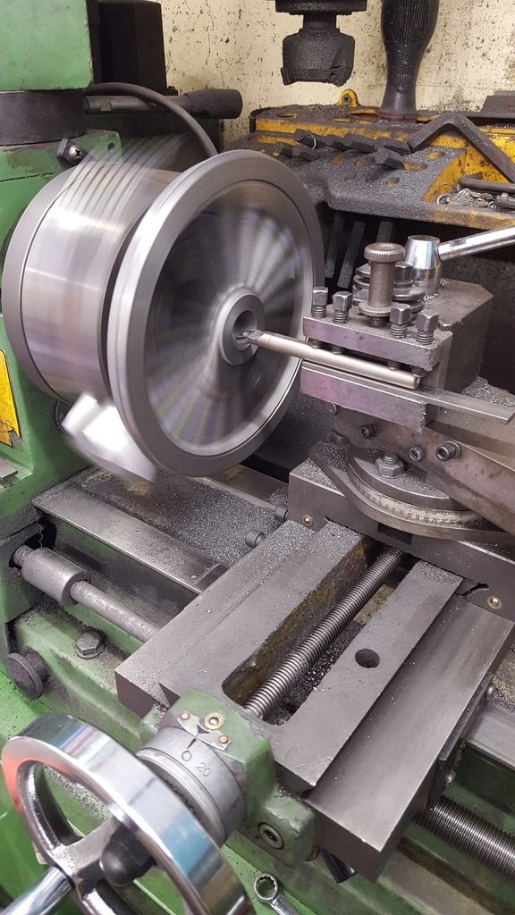
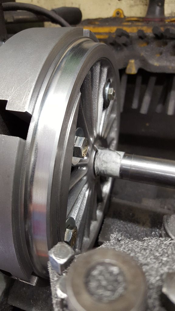
To help setup in the 4 jaw I used a scribe in the height gauge fixed to the topslide to get the wheel central which in this case is one of the main drivers, (these have larger weights than the leading and trailing drivers) checked for run out and also eye balled the front face to see if the casting looked concentric which it did. I studied the drawings and photos to get a good understanding of what I needed to do and in what sequence suited me best. With the wheel held securely in the 4 jaw (this took some time before I was happy) I carefully machined the rear of the tyre keeping an eye on what I needed for material thickness for the front. I have deliberately only taken a small amount off the back, reason being that on the prototype the spokes are very close in width to the rims, closer than it seems they will be on the model which makes sense as 5" gauge wheels are a little thicker than scale as I discovered on the front bogie. So I'm thinking of machining the fronts close to scale in as far as spoke edges being close to the rim recess and leaving the excess thickness at the rear which is not seen. I'm probably over thinking this and will make a final decision when I do the fronts, the wheel treads and hub bosses will of course, be correct no matter which I decide, hope that all makes sense. Picture shows the rear boss being centered and drilled ready for boring.
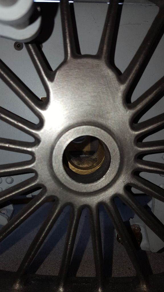
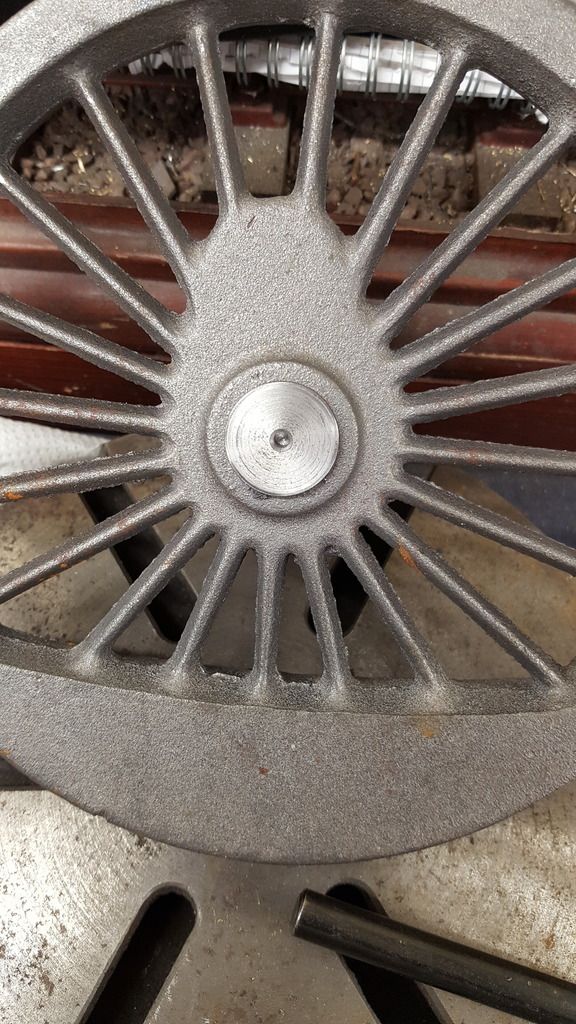
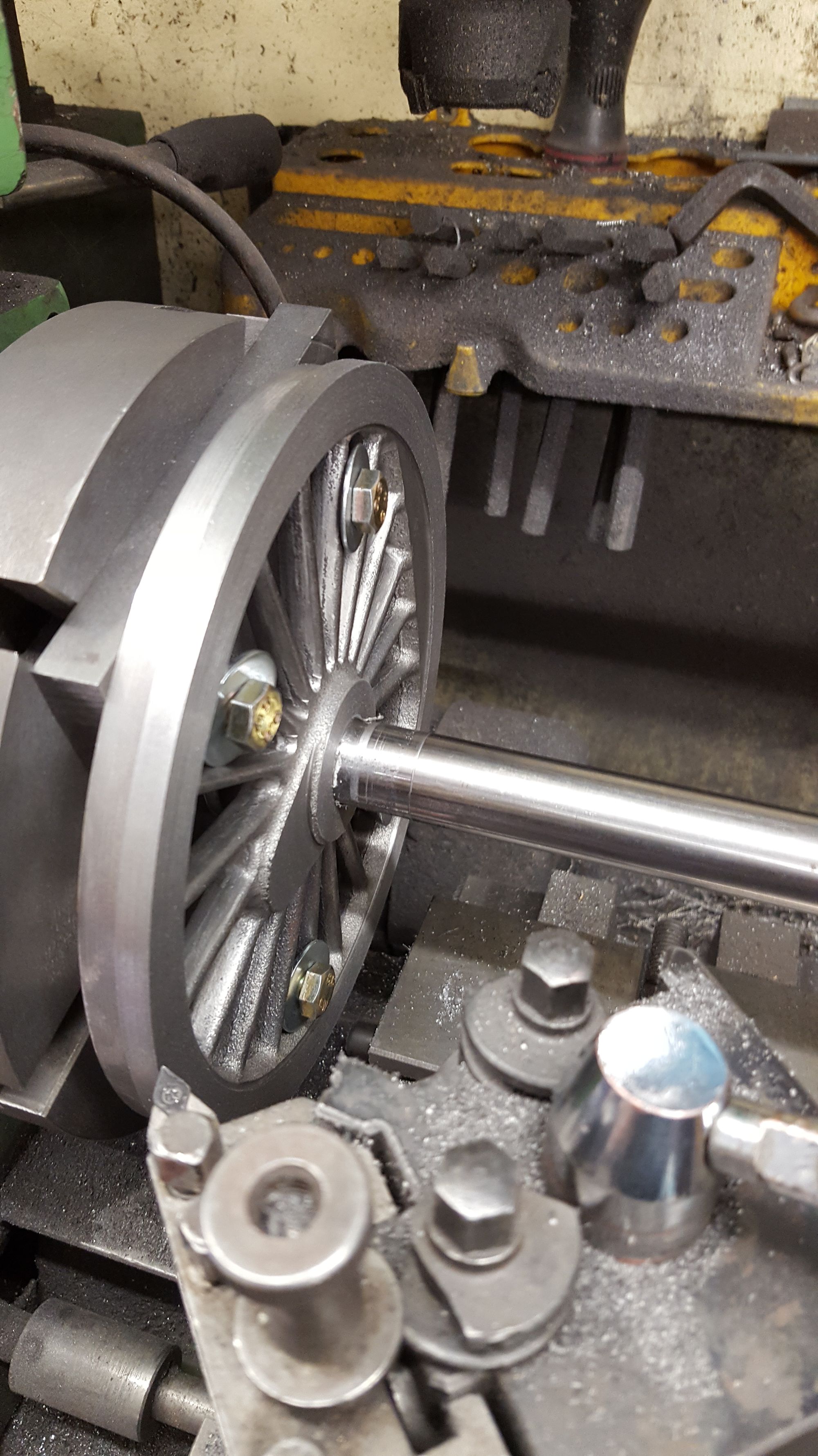
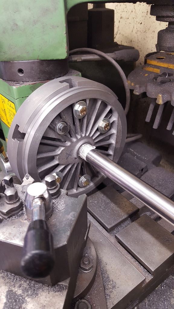
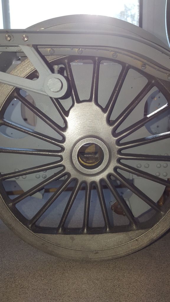
After a series of step drilling and then boring I have the bore at the required size, in this case, a fraction under 7/8th. The stub axle seen in the bore is 7/8th silver steel that has been polished on the lathe to bring it very slightly undersize, I wanted a good fit for wheel to axle but not too tight as I'll be keying/broaching/bonding wheels/axles together. The rear boss is 3/32 off the rear face of the tyre.
The wheel tread is oversize and will be taken care off once fitted to the backplate when I can do all 6 wheels with the one cut setting but for now I have made a start on the rear 3/32 rad, as per others this was done by hand.
With the rear finished for now, rear of balance weight and rim step cutting machined I removed the wheel from the chuck to check that the bore was central as it had looked, happy to report that all's good so far. Yes, I know that many bore from the front and I could have done likewise but when looking at the castings it was clear to see that the rear boss/rim was easier to line up on, plus Don stated to machine from the rear so that's good enough for me...
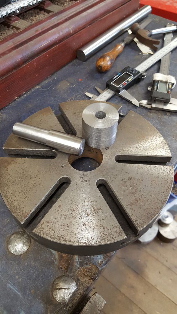
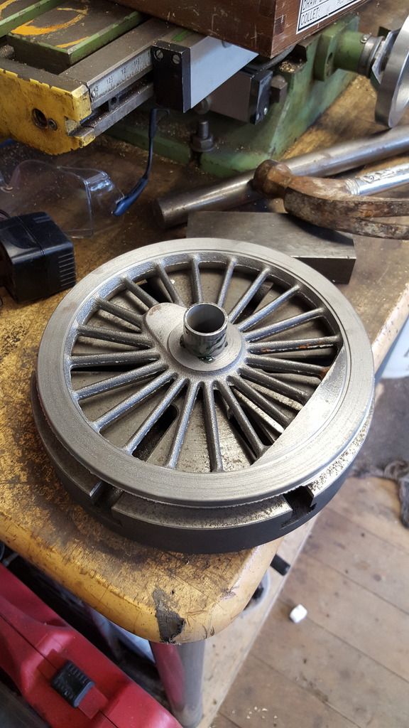
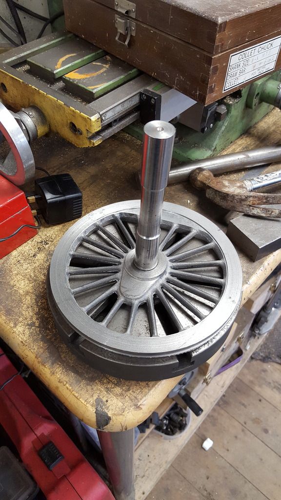
Ok, so a little explanation of how I plan to do the fronts (only done one rear so far so it will be a few days yet) The picture shows the backplate, a machined centre bush and the spigot already seen. My plan is to first fit the backplate, bore the center for the bush to fit tightly and then once fitted bore the bush to fit the spigot, final operation being a facing cut across the backplate. My reasoning being that this will give me the best chance with the equipment to hand of getting the wheels running true for final machining . The spigot has been centre drilled deeply so that I can clock it running true using the tailstock for each wheel. The backplate will be kept for future machining of other wheels or anything else that requires a mandrel of sorts as other sized spigots can be easily machined to fit the bush which BTW is large enough so that it sits flush against the backplate mounting and not get pushed through the spindle hole( no taper on this). Again I hope that all makes sense...
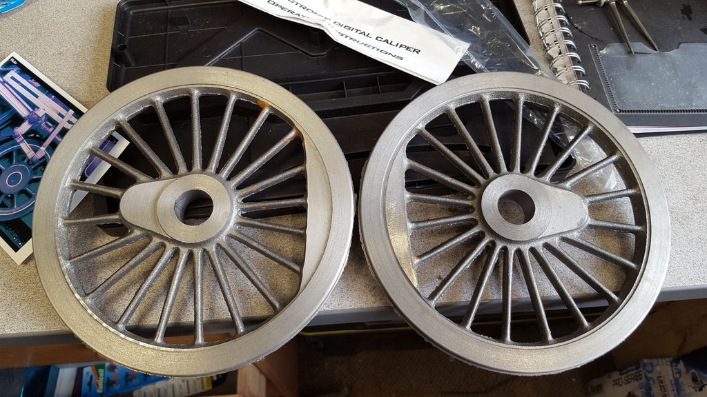
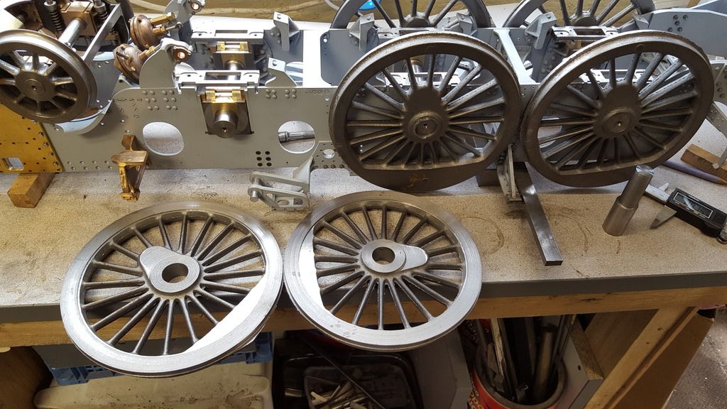
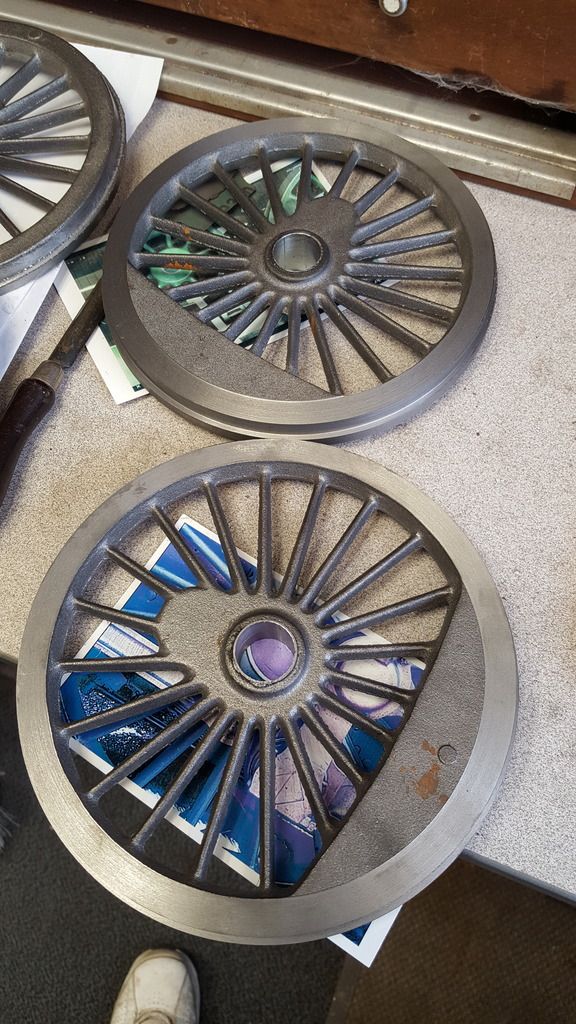
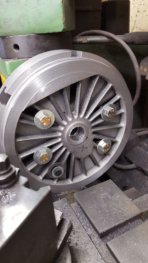
A little more progress today and a bit of a mystery too, I have now roughed out the backs of 4 wheels, the 2 main drivers and 2 of the coupled wheels, whilst machining the first coupled wheel I came across an unexpected fault/mystery. On these wheels, the backs of the wheel are at the same setting as the crank pin boss which then steps out 0.093 thou for the central boss. So while machining the wheel back I was a little surprised to find that the crank pin boss casting was set in a lot further than the wheel tread casting. So I had to remove more material than expected before being able to face the rear of the crank pin boss, so much so that it would entail removing some of the balance weight? I decided, for now, to just concentrate on getting the rear of the wheel tread and boss machined and not stepping in the balance weight which leaves a groove between the tread and weight on one wheel as shown in the next picture. The picture shows two coupled wheel backs for comparison to hopefully show what I'm talking about, the one on the right is the one that the casting has less depth in and thus the odd one out. For now, I have machined both down so that the wheel spokes are at the same depth from the rear of the crank pin boss, I will revisit these once on the backplate. Hope that all makes sense?
This is just me being true to form and not resisting the temptation to put the 4 wheels that have been machined so far on their respective axles...well it just had to be done...
Well today hasn't been such a good day but the bad needs to be shared just as much as the good, I'll explain but first a step back with a missing picture to show how I do things, Here is the first stage of boring, well actually the second after centre drilling but here's the first stepped drill, I used 4 steps up to 1/2" and then took about 20 thou off with each pass of the boring tool, just over 20 passes. Final cuts at slow feed and fine cut, I would check the size a number of times during this exercise.
Now to the bad part....I was doing the final cut on the final wheel and yes made the bore too big!...the annoying thing is I knew the cut felt wrong as it started cutting, I took a quick look at the dial which looked fine, what I had forgotten was the problem that I've had in the past where the dial had jammed and thus not registered the true value of the cut? ( one of the bad points on the Warco, the dials work their way loose) My own fault, I have been meaning to do something about this for a while, guess this has reminded me that it needs doing, more annoying is the fact that if I had got around to cutting down the spare glass scales that I have for the DRO and actually fitted the damn things this problem would have been null and void...lol
Anyway a picture to tell the story...wheel on the left is the bad one. What I will do is machine up a bush that has an OD small enough to allow the broaching operation to cut right through it but large enough to give plenty of strength to the bush, I have ordered some precision steel tube for this job, the bush will be bonded in.
NB: the above solution was my first thought, this was changed as explained soon.
NB: This set me back a few days but I had plenty more to do>
I won't do any more machining on the wheels as I'll need the 4 jaw to make the bore bigger for the bush and I don't want to fit the backplate only to have to remove it again until all relevant machining has been completed. So I have turned my attention to the flash around the spokes/boss, picture shows the difference , right hand side being that which has had some time with the files, I reckon an hour's filing per wheel, at least it will keep my mind off that last damn cut??...yeah right.....
Ok, on to my solution for the error in the last bore, I ordered a length of 24mm OD precision steel tube and decided rightly or wrongly to bush all of the wheels with this precision steel. First, I cleaned the lathe/cross slide and dials and also set up with a fresh new boring tool. I also took the decision to bush out all 6 wheels, rather than just the bad one. The reason being two-fold, first that I hate odd dimensions in the mix but also a change of plan for fixing wheels to axles. Quartering will still be registered by keyways but rather than a sliding fit to be bonded, I plan to use press fit with bonding too.
So, first picture shows the last wheel with final cut on it's second pass. I took much more care this time, with constant bore size checks, a few longitudinal cuts for loctite 638 and 1 thou undersize for a drift fit. Having done the first wheel it was easy/quick to use the same final setting for the rest.
Next job was to drift the bushes into each bore, as can be seen, each wheel was placed on the backplate, bush tapped in approx 1/16th, loctite smeared on both the bush and the inner bore and then driven home. As stated this is not any old steel tube, it's precision cut and very tough.
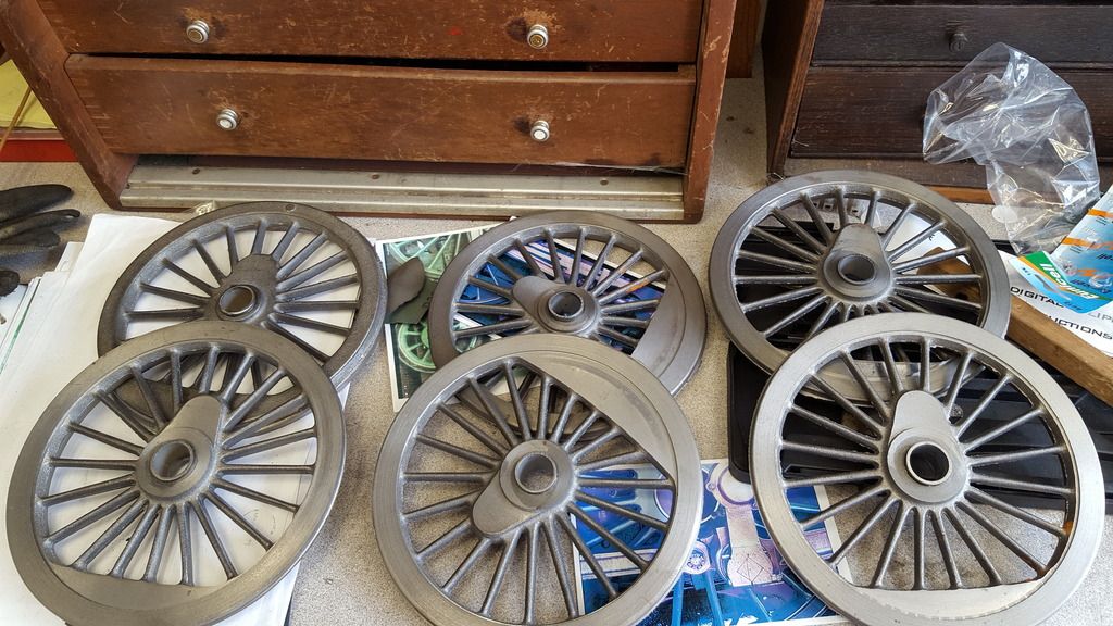
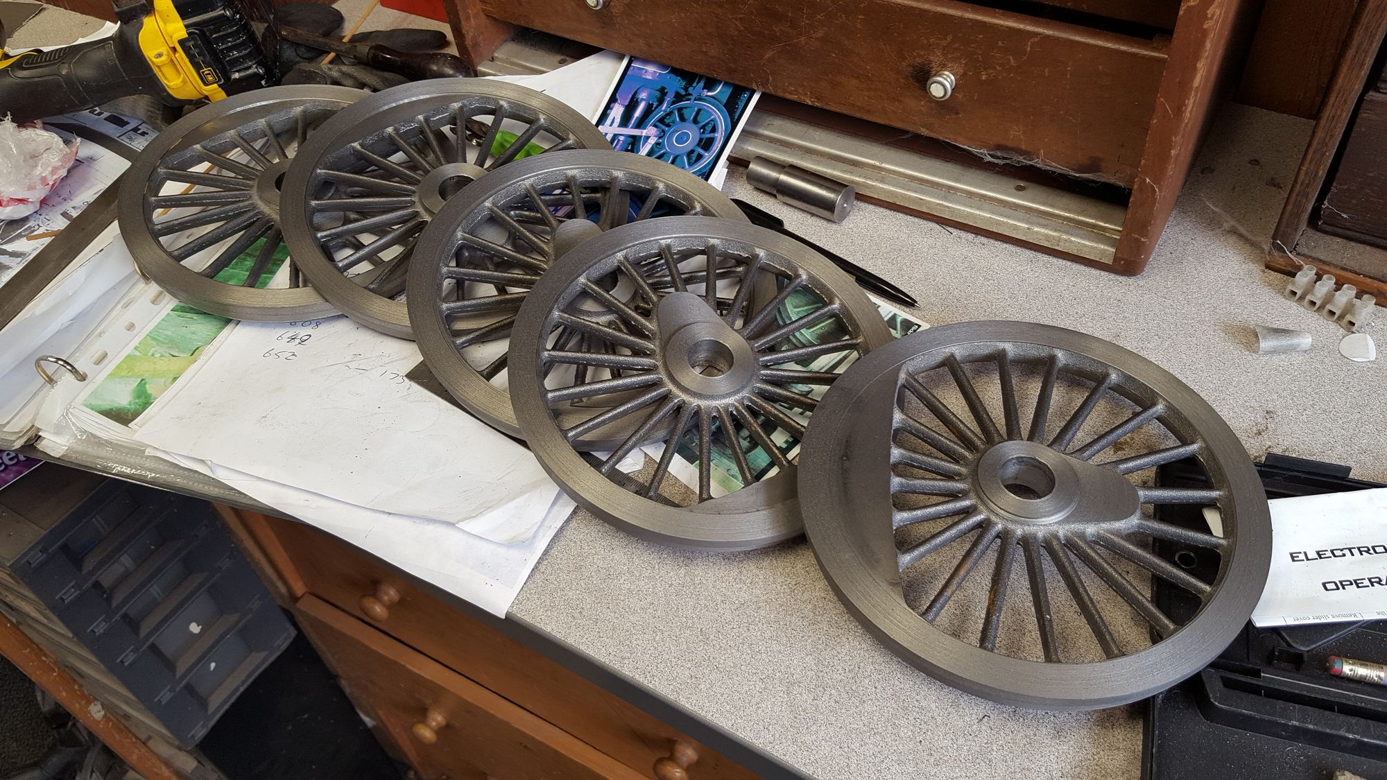
Lastly picture of all 6 wheels at this stage, next, I'll re-set each wheel in the 4 jaw and machine to final bore size, this time though, 1 thou undersize for a press fit to the axle. The bushes are overlength so that they more or less disappear after final machining...no one will know....well except you guys...
NB: Just to explain my way of thinking, the bushes are now fully bonded to the wheels, the wheels will be broached for the keyways, the broaching will cut through the bush into the wheel casting and thus the keyway acts as a stop removing any possible slipping of the bush, IE, no undue pressure on the Loctite bond itself, not that this should be a problem anyway as they are a drift fit too, just me making sure on no future issues.
Ok so moving on, after a 24hr cure time to give a good strength for bush to wheel, I have now bored out all 6 wheels for a press fit. I took as much care/time as possible clocking each wheel in the 4 jaw, rear face out ensuring that each wheel was both central and square to the lathe axis. This was a lengthy process having no machined surface to hold in the jaws but am happy with my efforts..
Even though all wheels were machined on the same final setting I still checked each one a number of times before making the final cut, last thing that I needed now was a repeat of last weeks error, no thank you. Once machined, each wheel bore was checked by drifting in the axle a short distance , this was really just for my peace of mind...
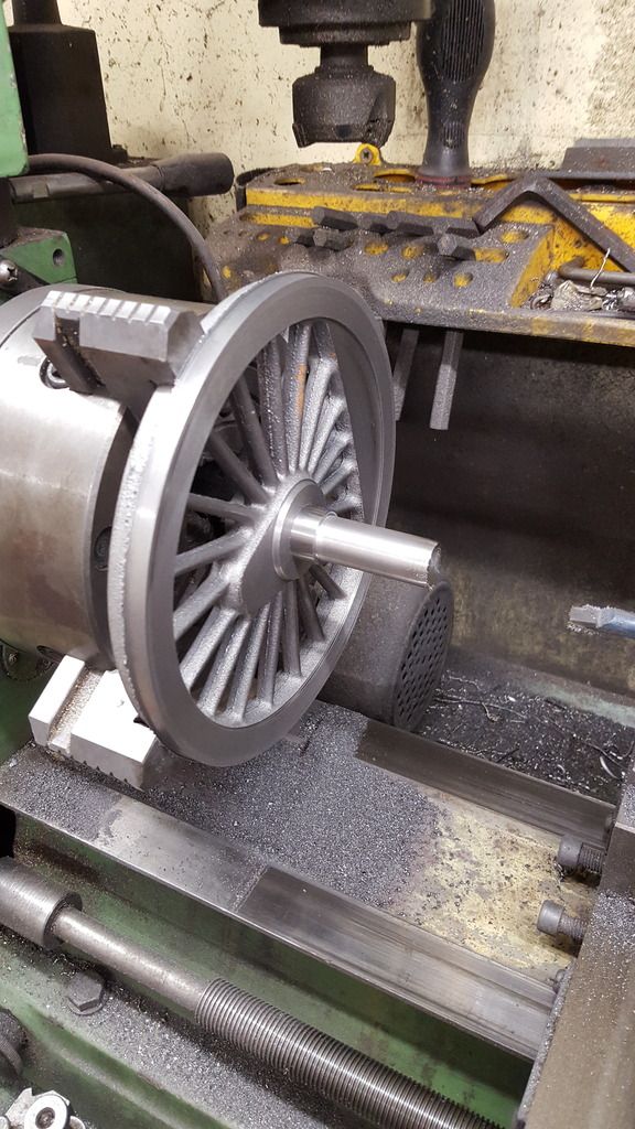
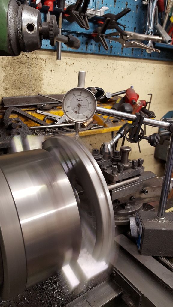
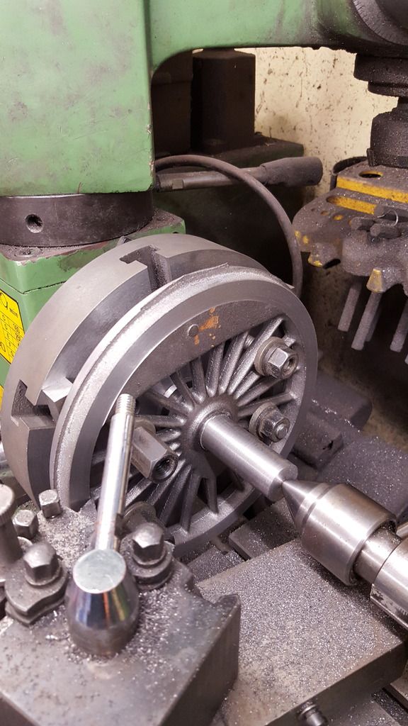
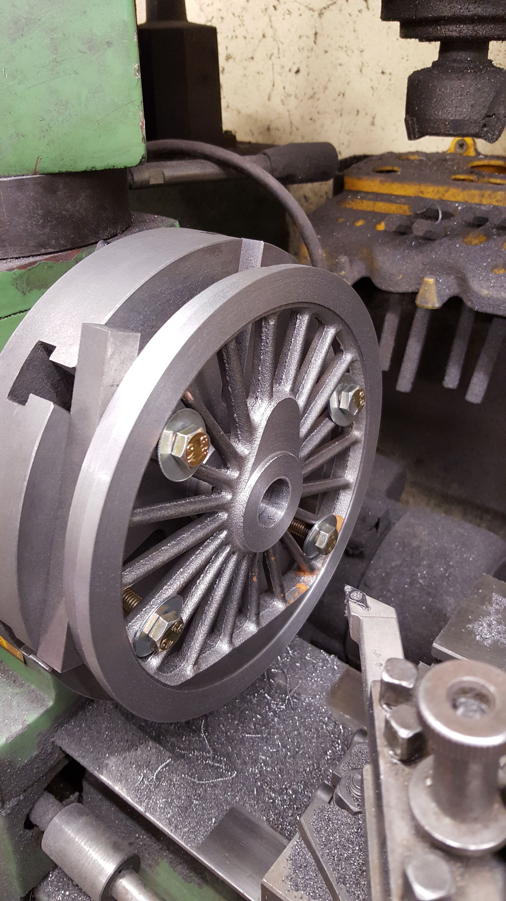
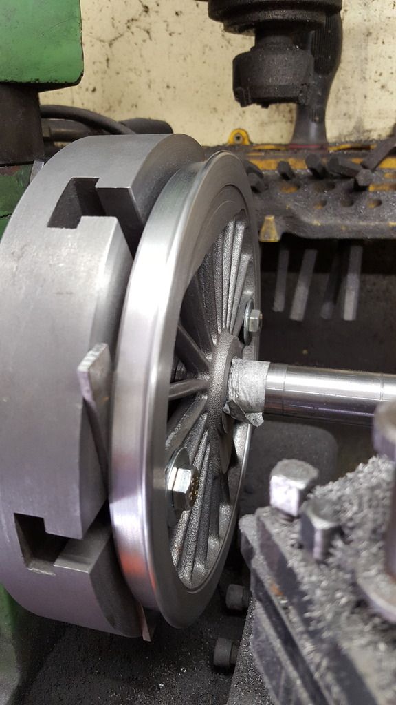
Having finished the machining of the backplate and spigot (sorry I forgot the picture, oh and I made a new spigot as I needed it longer for clearance ) I set up the first wheel to skim the front face ensuring it was parallel to rear and square to axis. Spigot is a good close fit to bore and a live center is used for added concentricity. Picture shows the first wheel (main driver) after having the tread face machined until it was flat so that when I return to final machining of the rear face I have two datums to line up with, front face and bore axis. Note that the balance weight sticks proud of the wheel tread, final size will be 1/16 proud . None of this can I do yet needing to finish the rear first but also the fact that the securing bolts are in the way.
I have two planned stages for dealing with this, first will be to do all the roughing out using the large 10 mm bolts and then finish the balance weight/boss machining with smaller 8 mm bolts, if I think I can get away with it I'll machine down the bolt heads for clearance, the spigot being removable makes facing the centre boss an easy affair. If this doesn't work I may have to do the final cuts back in the 4 jaw or perhaps when taking the very final cuts when fixed to axle between centres?..
BTW the wheel is set 1/2" off the backplate using bar stock cut to length to bridge between two mounting points of which there are 4, In the picture, one bar is sticking out too far, this was moved further in to allow machining of the outer flange diameter. Everything was checked for being securely held before machining began, you don't want a piece of steel bar flying out , a little dangerous to say the least.
This picture was to show the main drivers having had the tread face/diameter and flange diameter machined, well roughed out, still a long way from final size.
I managed a little time today to finish the rears except for the final cuts on the rim lip which I hope to make a start on tomorrow. These wheels at nearly 7 1/2" make life a little problematic at times for set ups, but things are moving along nicely.
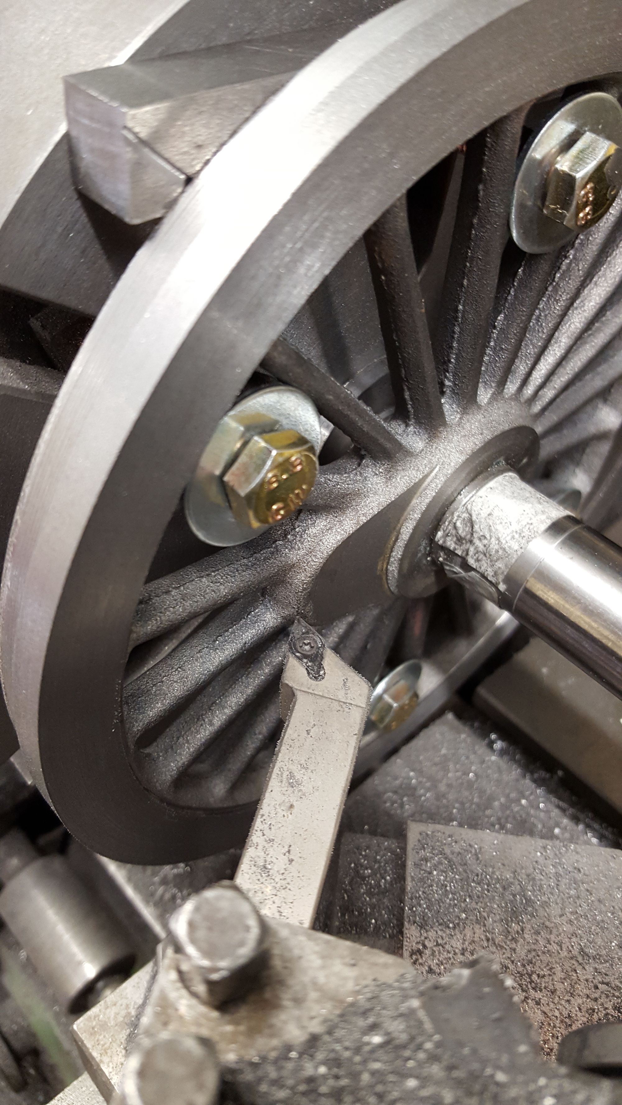
First picture to show what was involved for the tread rear face, crank pin boss and centre boss. As can be seen, I've changed to the smaller 8 mm bolts in place of the 10 mm studs/nuts to give more clearance, the method employed was to machine the tread, stop, move cutter past bolts and then machine the crank pin boss, I did this procedure until the thickness from front balance weight to rear tread was approx 0.630. Reason for this long winded affair was again, lack of trust on the dials, they are fine for accuracy in measurement but useless for repeat accuracy.
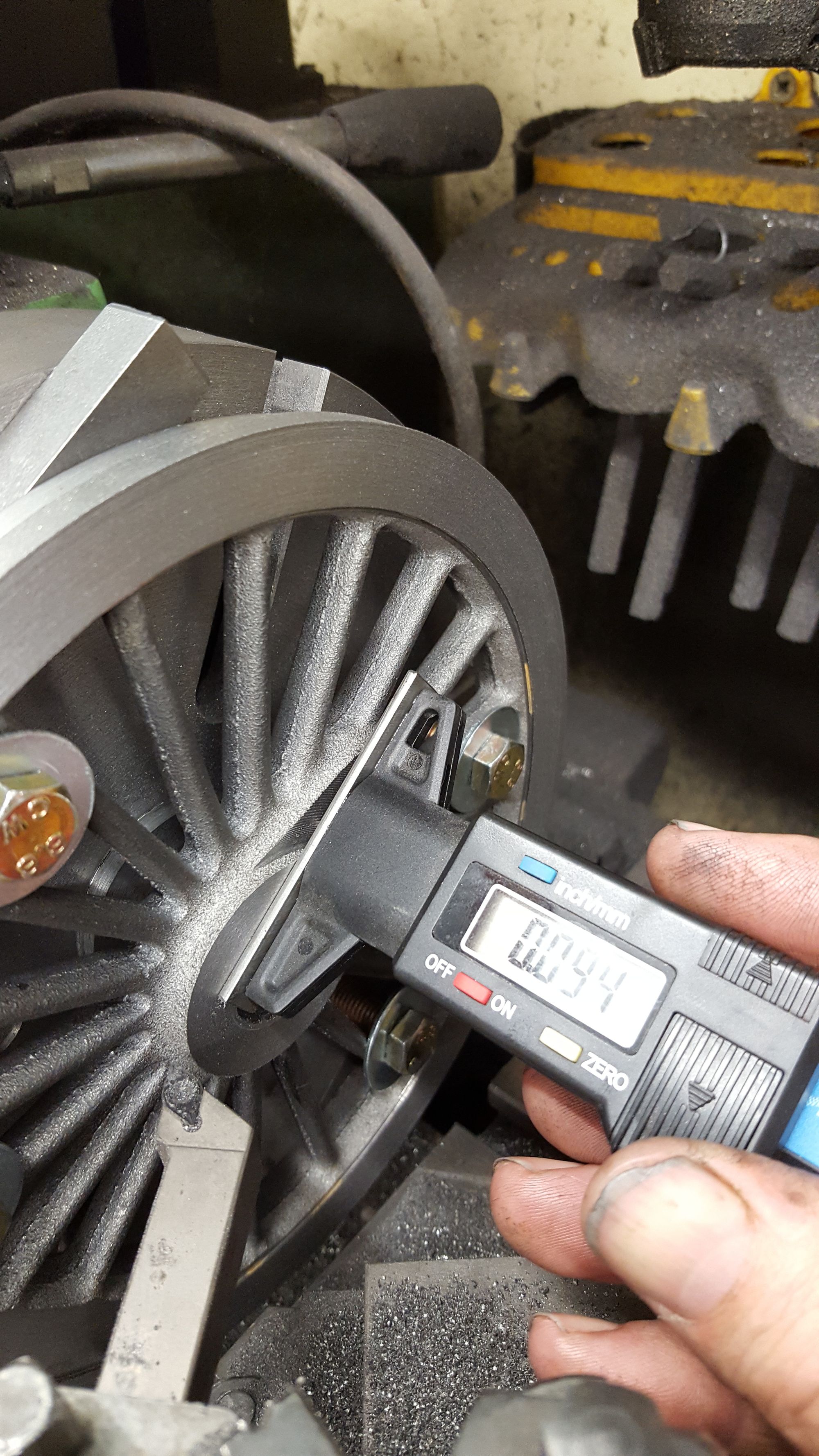
Next was to machine the centre boss to size, like most of the measurements on these wheels, this needs to be accurate to ensure no problems when motion mates with cylinders. With the spigot removed ( it just slides out) it was a straight forward job to machine away the protruding bush and then the boss down to a step of 0.94. The drawing states 3/32 which as you guys know is 0.9375, my gauge doesn't go to that resolution so I decided on 0.94, why use a depth gauge and not the dials? think that's obvious....
A word on the gauge, it's a very cheap affair but pretty accurate with a small modification employed , I've seen this done elsewhere before but can't remember who did it, my apologies for not giving credit where due. Anyway the mod just involves a short length of flat steel Loctited to the plastic base, this gives a nice solid flat face to measure from, I did a small test on a known step to check that the gauge measured the same from either side, which it did.
With the spigot re-positioned between centres I then tackled the flange diameter, I machined each flange to 7.412 leaving a single cut of 6 thou to achieve the final size of 7.406. as stated before this will be done between centres after the wheels have been pressed onto their respective axles.
And so we are at this stage, this is the sixth wheel left on the faceplate ready for the final two operations on the rear which is the inner rim step and rear radius of flange, I may need to grind up some tool steel for this.
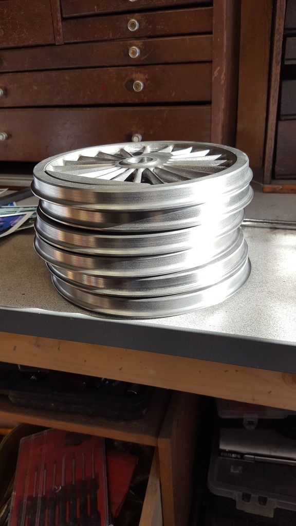
This picture shows the other 5 wheels ready for the next stage...getting there, slowly but surely...
With the rear's near finished (no radius yet) I could prepare the backplate ready for doing the fronts. Now that the rear boss was faced too size I machined out a recess from the spigot boss so that I could get the rear of the tyre's and crank boss flat against the faceplate giving me the best setup for getting the tread with hopefully no run-out. There are of course a number of ways of doing this, I chose this particular method mainly due to the large diameter of the wheels. Picture hopefully shows what I'm talking about for setup, the tread has been machined to size (depth).
With the spigot removed I could move on to facing the axle boss, something that I hadn't realised till now was the fact that the boss is at the same depth as the tread and not 1/16 proud as I had originally thought, it's the crank pin boss that's recessed by 1/16th. I haven't machined this boss yet, will leave that for later when I can do all at the same setting, it doesn't need much more than a skimming down.
Next, I moved on to the tread diameter, here I used a profile tool for the flange and machined to +50 thou for now, no taper yet and the root rad is slightly oversize, I'll get in closer when doing the taper and again leaving final machining for when fitted to the axle.
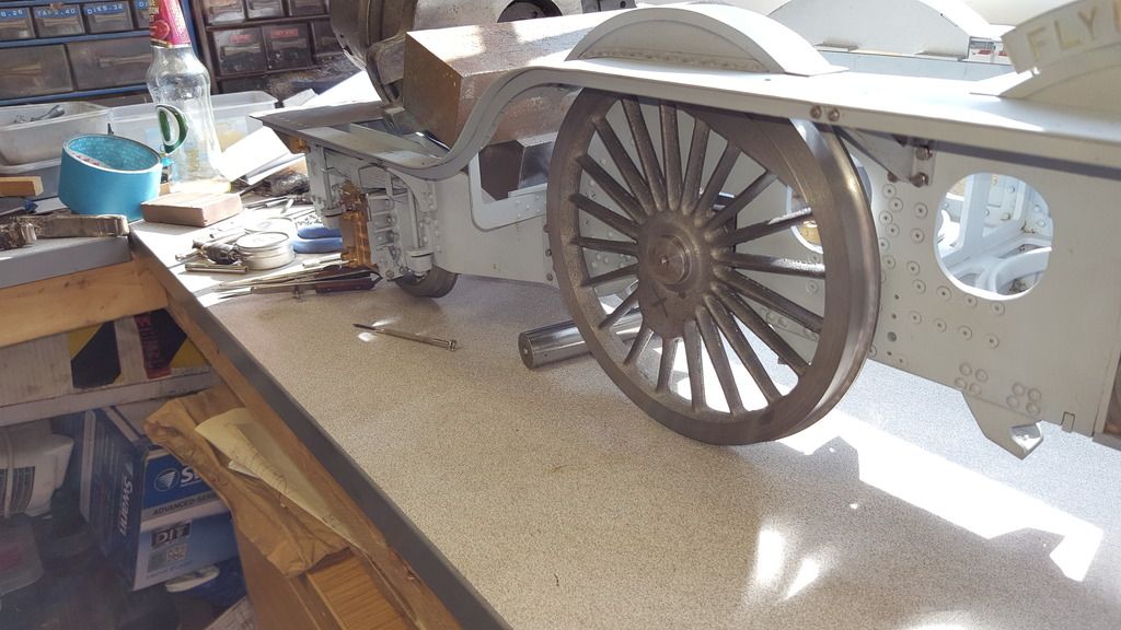
And so the first wheel placed in position ( well it had to be done..) on a suitably sized piece of BMS bar just to get a feel of how things are progressing. I have weighted the chassis down a little (about 60lb's) for this picture but it's presently riding a good bit higher than it will be when fully loaded, the good news is when pushing further down on the chassis to approx running height the wheel turns freely without binding on anything such as the splasher.
To catch up with where I am, in general, I now have all wheels to the same state, plus I have machined the crank pin boss and made a start on the rim lip recess. The lip recess is a little problematic due to the balance weight being included in the casting, perhaps it would be better to have this as a separate piece? I looked long and hard at various pictures before deciding what to do with this lip, the easy option would be to start the lip on the outer edge of the weight but that wouldn't look right to me, it probably is right as how else would they machine it if one casting which I think it is. I could be wrong but to my eye the lip looks a tad wider than the groove around the weight so using a ground up tool I machined a small square edged lip just touching the outer edge of the balance weight, this left a very, very small lip around the inner edge of the rim ( can just be seen in one of the following pictures) , this I will scrape off while on the faceplate and by hand to finish. I probably haven't explained this very well and as I said I could be wrong but hey if so such is life, it's so small it will probably never be noticed...mind you, you lot know now.....
I have also deviated from one of Don's measurement's, that being the 1/16th protrusion of the balance weight from wheel tread, this just looks wrong to my eye , too heavy, plus after it's painted will be thicker still so I took an executive decision and reduced it slightly.
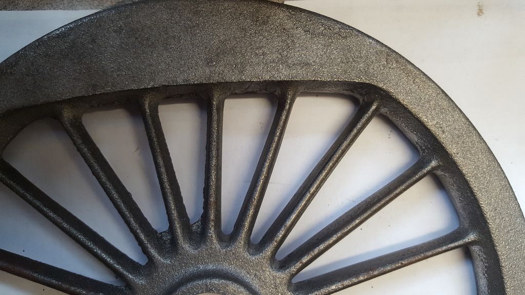
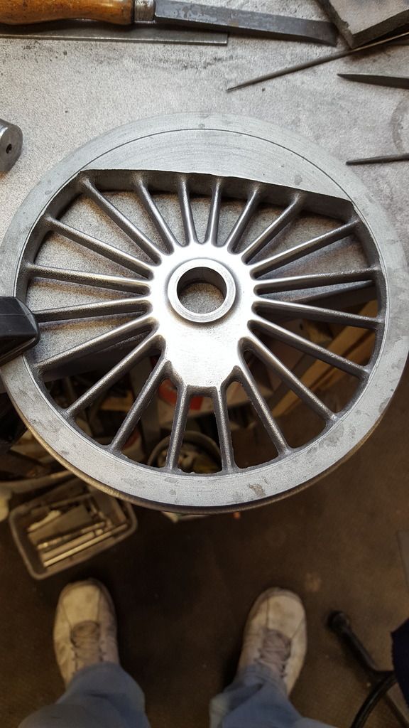
Now after doing all that, I decided to make a start on the filing which would leave just the final machining of the tread taper and rear radius to do before moving on to the crank pins. First picture shows one of the coupling wheels that has been filed around the spokes, I spent half a day on this as I wanted it to look good, IMHO the natural casting finish is too heavy scale wise to be left as cast. I was going to put the wheel on the spigot (as per usual) that I turned up to fit but some fool left it out in direct sunlight all day with obvious results...so here the wheel is just propped up for the photo.
A close up of the boss after filing and polishing...

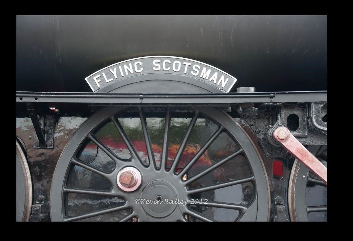
A picture of full size for comparison...this picture isn't mine, I found it online, but with the motion removed it makes comparisons easier..
NB: Now some will point out the the boss profile is wrong when compared to full-size, well it is and it isn't. Today, 4472 has A1 peppercorn wheels fitted which have a different crank boss profile, Don's castings match 4472's wheels as they should be.
For filing, I simply hold each wheel to the bench via a quick release clamp working my way around spoke by spoke, I still need to clean up the outer parts but that won't take long, just a simple matter of using some 3M sanding pads. This picture shows one of the main drivers close to being finished to this stage, just the 4 spokes along the bottom edge left to file down. I haven't scraped the lip yet either, will tackle that job next once all wheels are filed.
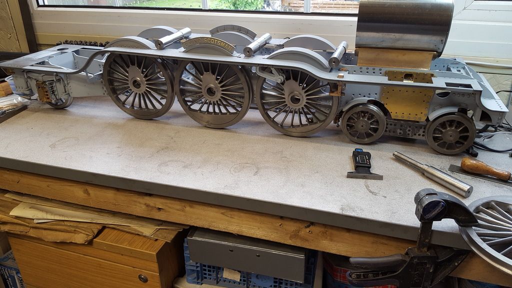
I have filed 3 wheels so far, couldn't resist lining them up with the chassis, she's actually starting to look like a locomotive now.
The plan is that before I tackle the crank pin bores I'll machine the keyways into the axles ( 113,127,120 degrees, once, that is I have it clear in my head exactly what goes where) and then do the wheels and crank webs all together using a jig (yet to make) to ensure wheels and crank webs are all identical.
I have to say that I'm looking forward to getting these wheels done, if for no other reason than that they are the last big cast iron components that I have to work on so no more dirty metal to deal with, the lathe will certainly have to be stripped down for a good clean once completed.
Final jobs now done to finish all of the turning operations for the main drivers which involved taper, chamfer and radius of flange.
First picture is for the 30 degree chamfer which ends 1/16th in from the front face, this actually was the second operation of the day, I have already machined the taper in this picture which follows the GL5 profile of 3 degrees. Both operations were done in one pass ensuring that all 6 are identical.
With the front face completed each wheel was turned around, packed out to clear balance weight and had the rear radius filed down by hand to it's final size of 0.93 radius.
Finally, here we have all 6 wheels ready for the next stage which will be drilling/reaming of the crank pin bores, IIRC 9/16th for the main drivers and 1/2" for the coupled wheels with the last job to do (other than general clean up before painting) being broaching for the keys.
So it's good to have the bulk of the turning now behind me, final turning will be when fixed to axles to remove the approx 4 thou left on the flange diameter and around 10 thou on the route radius of the taper, these again will be easy to do in a single pass with the axle held between center's.