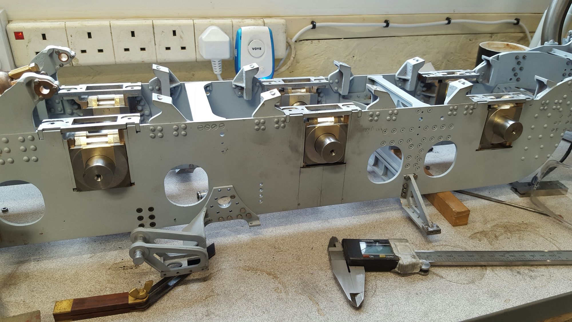
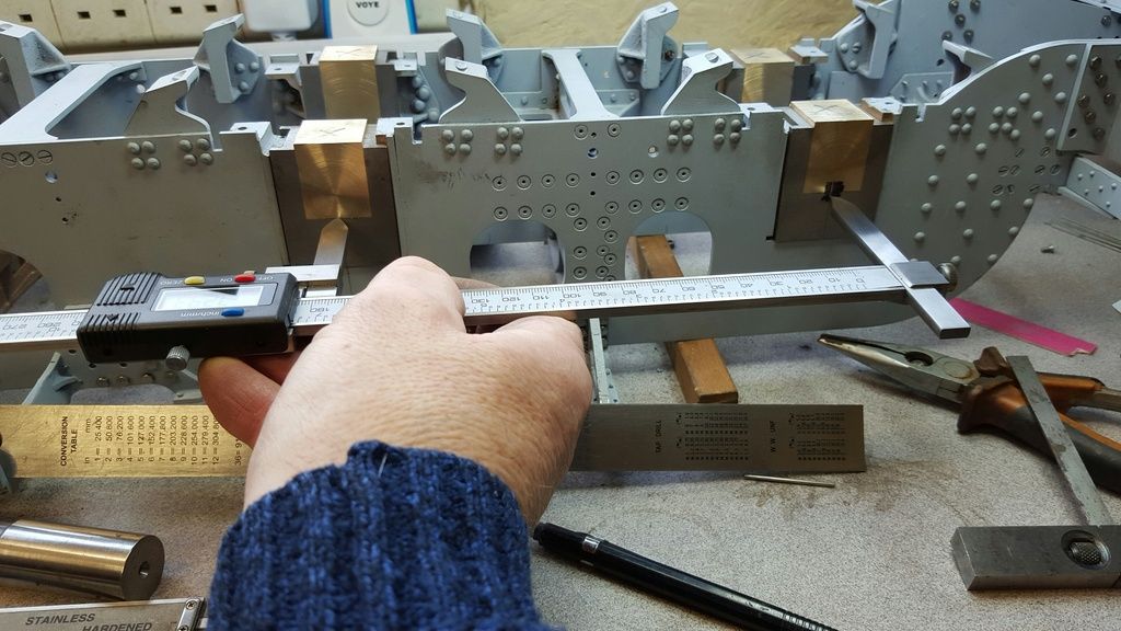
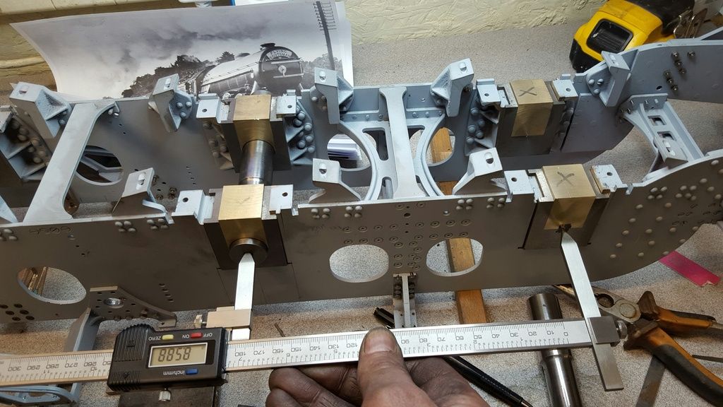
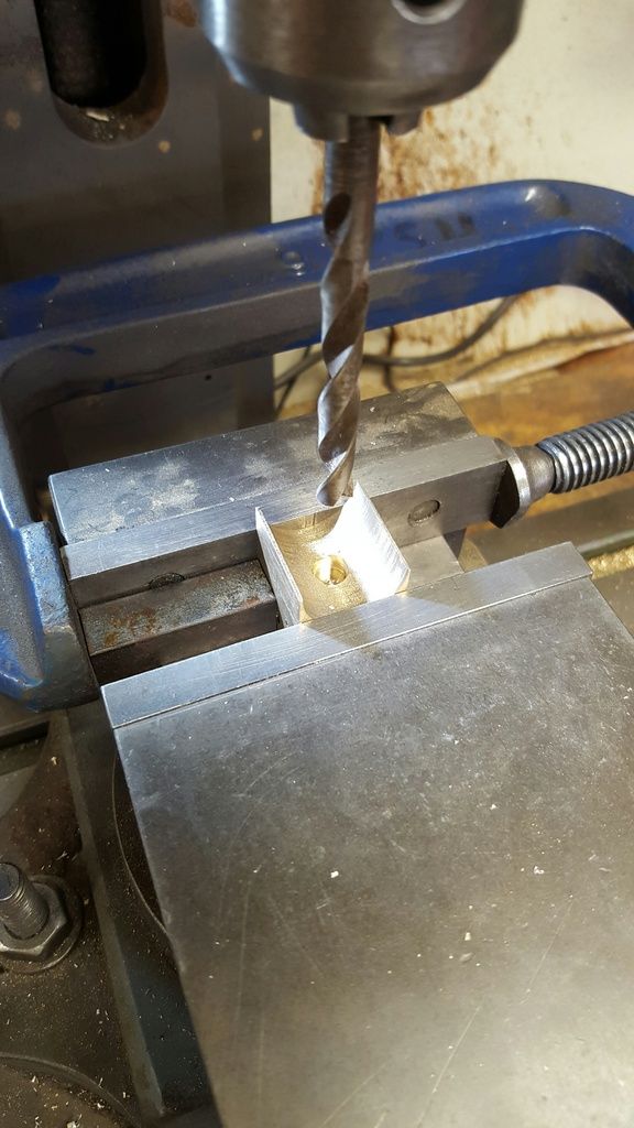
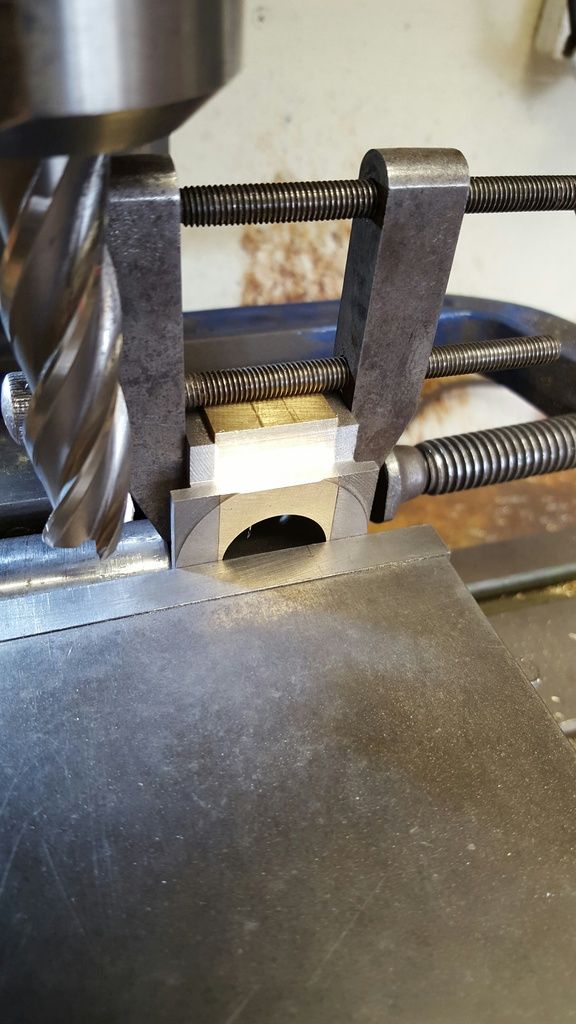
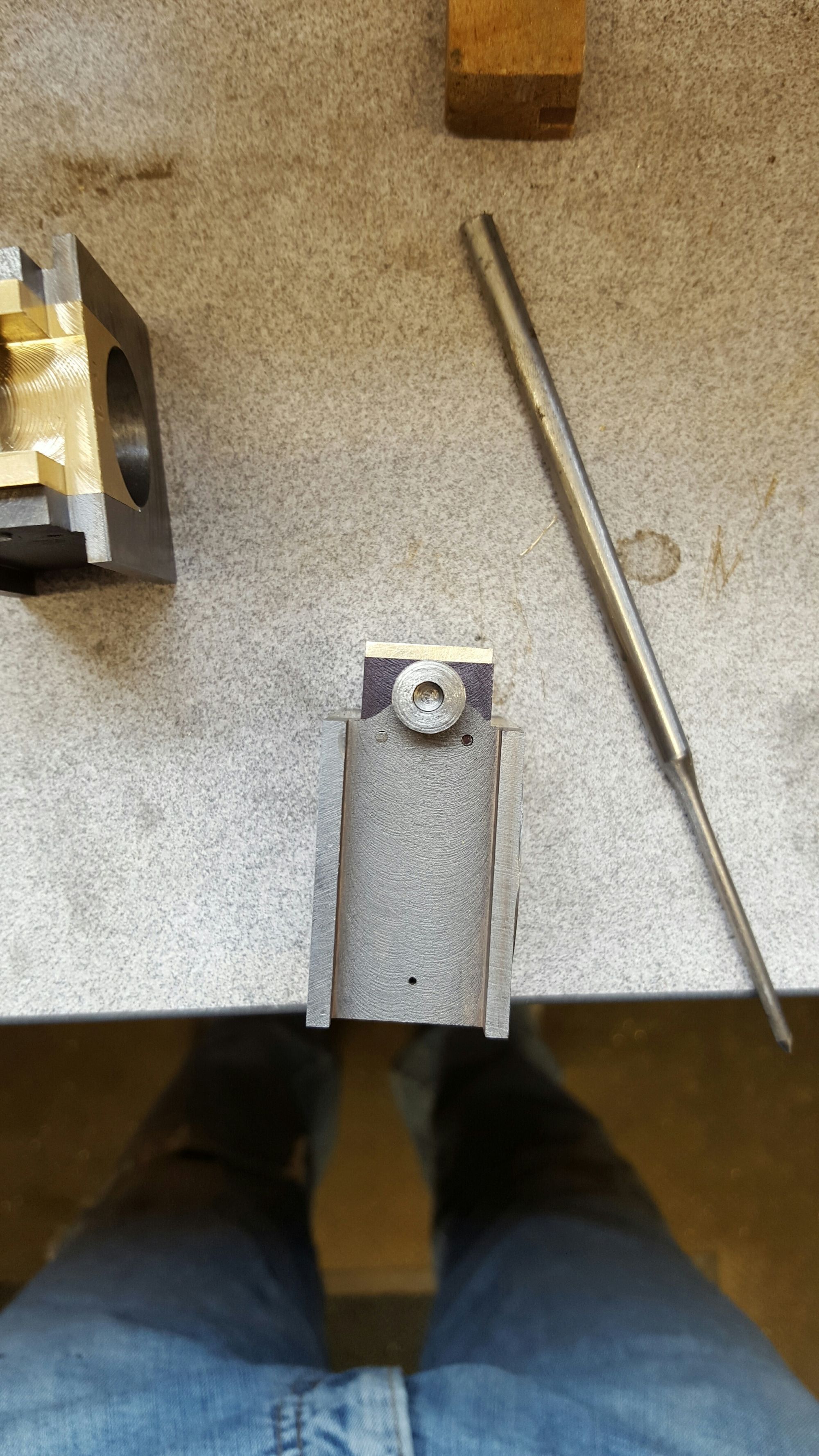
Main axleboxes continued, on to the important bit, well their all important but for this stage I have tried to be extra careful, after plotting the right hand side crank box centre (my datum) and then setting the vice, I spotted a small hole with a centre drill as shown here.
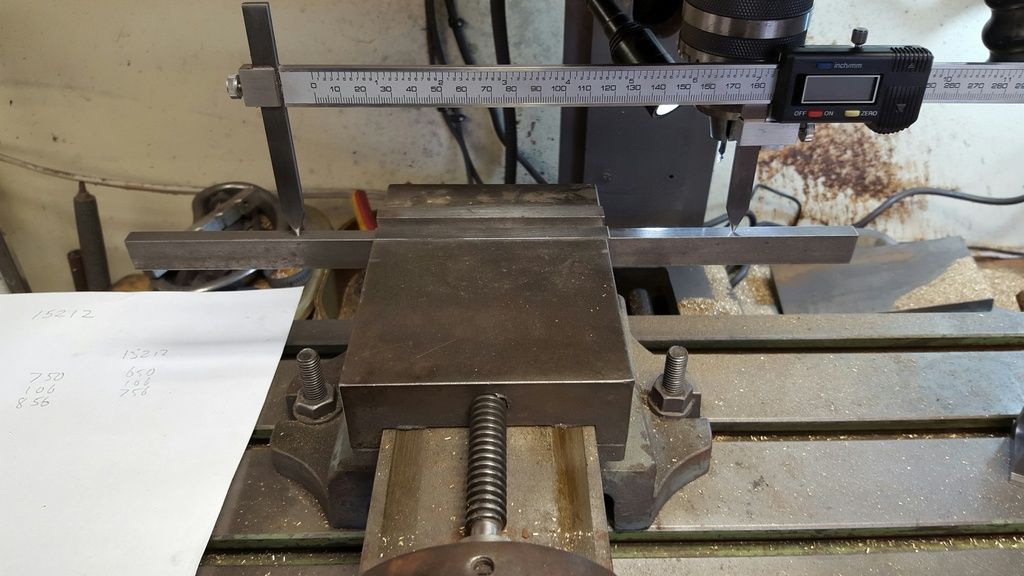
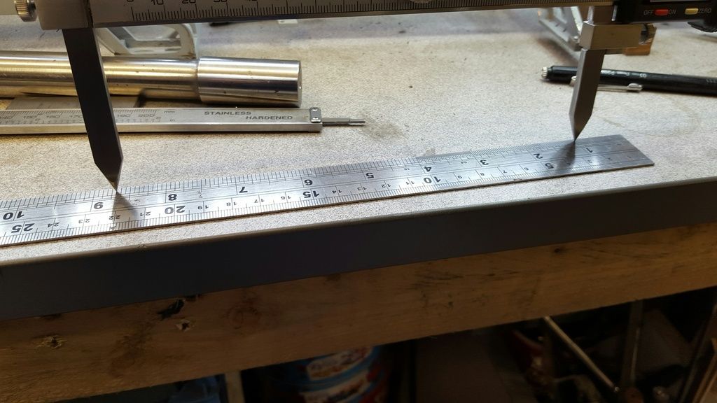
I then needed to set the point to point vernier to 7 11/16 distance between axles, I didn't want to just trust the vernier for this so chose to use the mill DRO, drilling to spot holes into a length of steel bar and using this to set the vernier which could then be used as a set of trammels.
Followed with yet another visual check...well I did say I was being careful.....
\it was then time to mark the centres for the leading and trailing axles...With the crank axle spotted and all axles having a centre line marked and put back in their horns, I used the vernier to plot the leading/trailing centre's which I'm happy to say lined up with the individual box center's that were marked when machining first began.
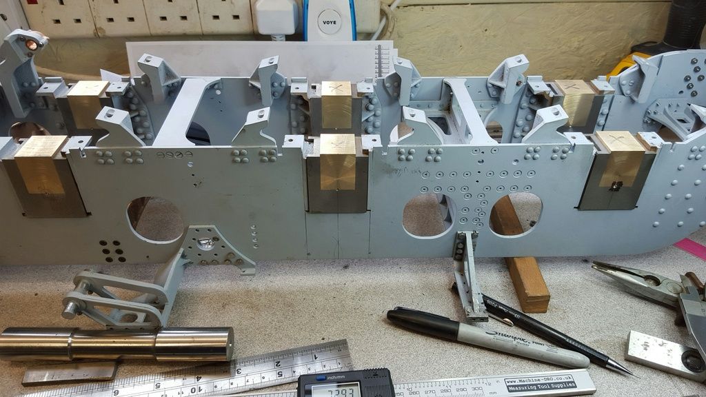
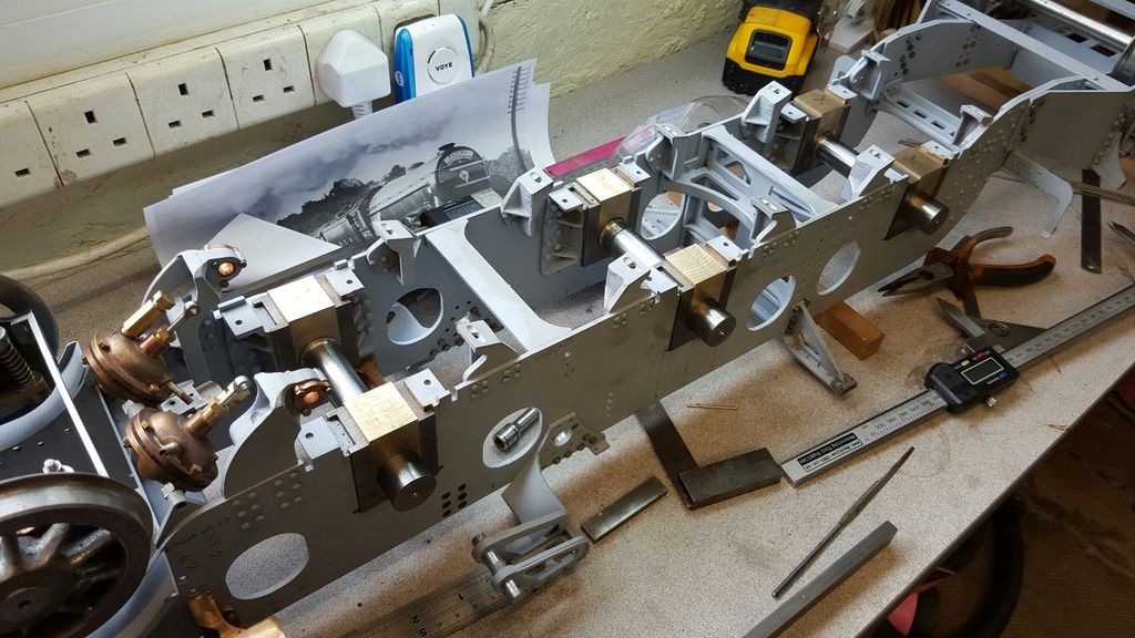
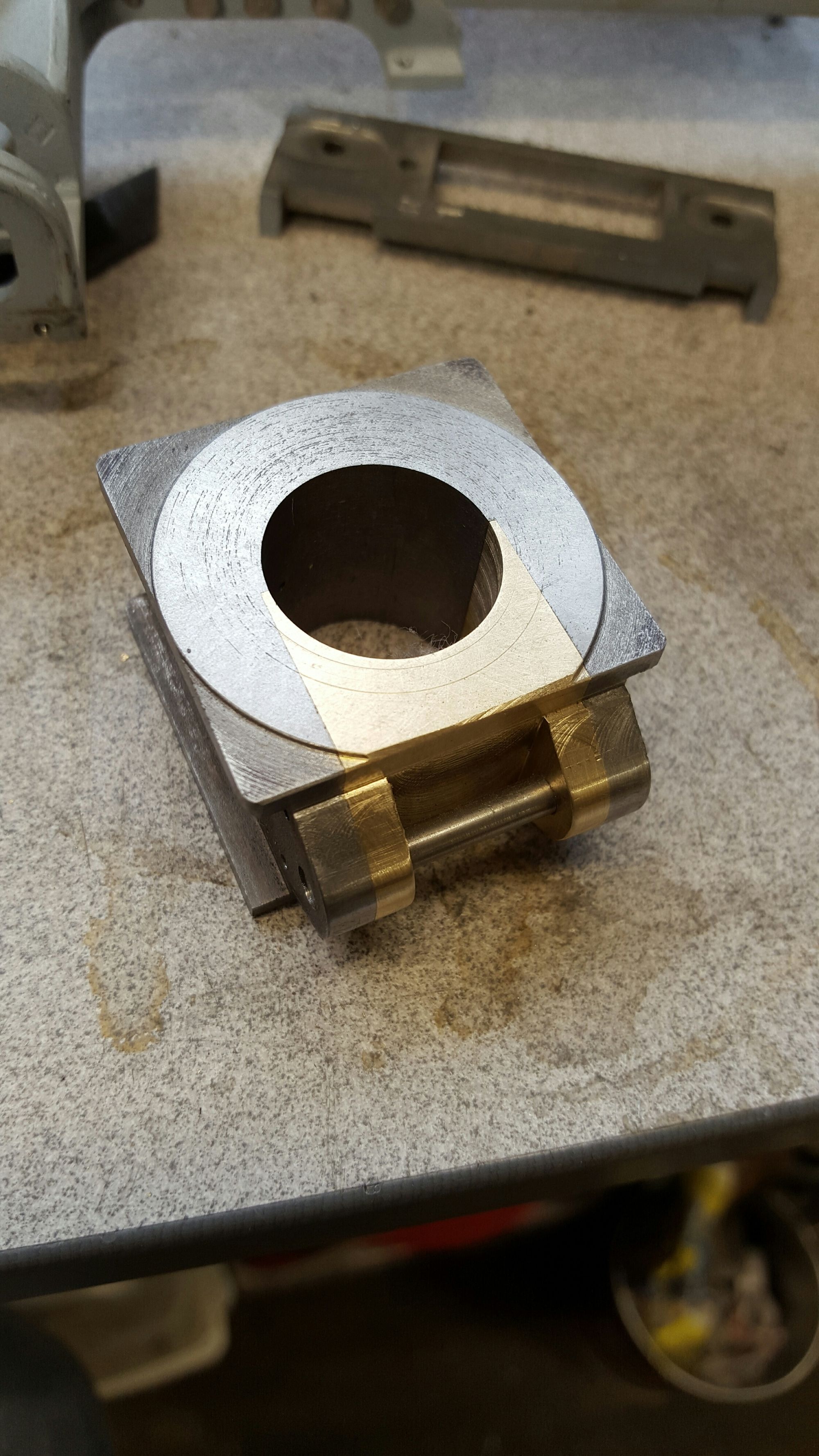
once marked each box was put back into the machine vice (registered) and spot drilled remembering to spot outside faces for nearest to camera and rear faces for the other side. This again was just me ensuring that the pairs matched, any error that occurred during boring would be much easier to deal with if both boxes where the same per axle, hope that makes sense?
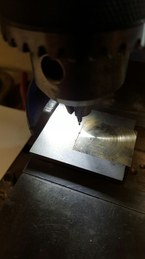
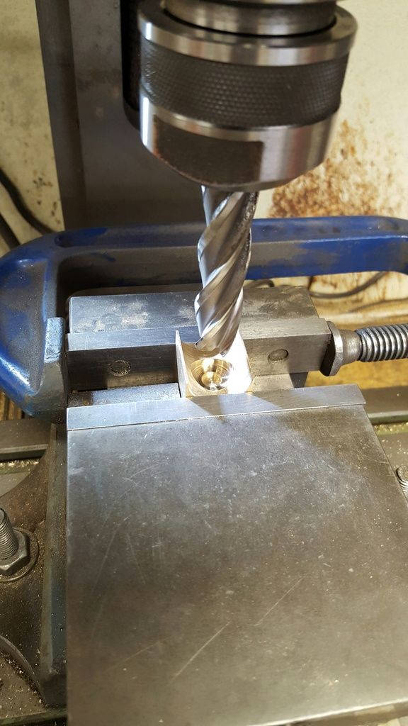
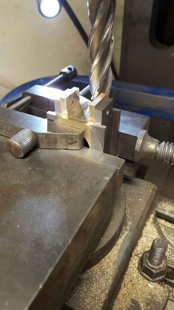
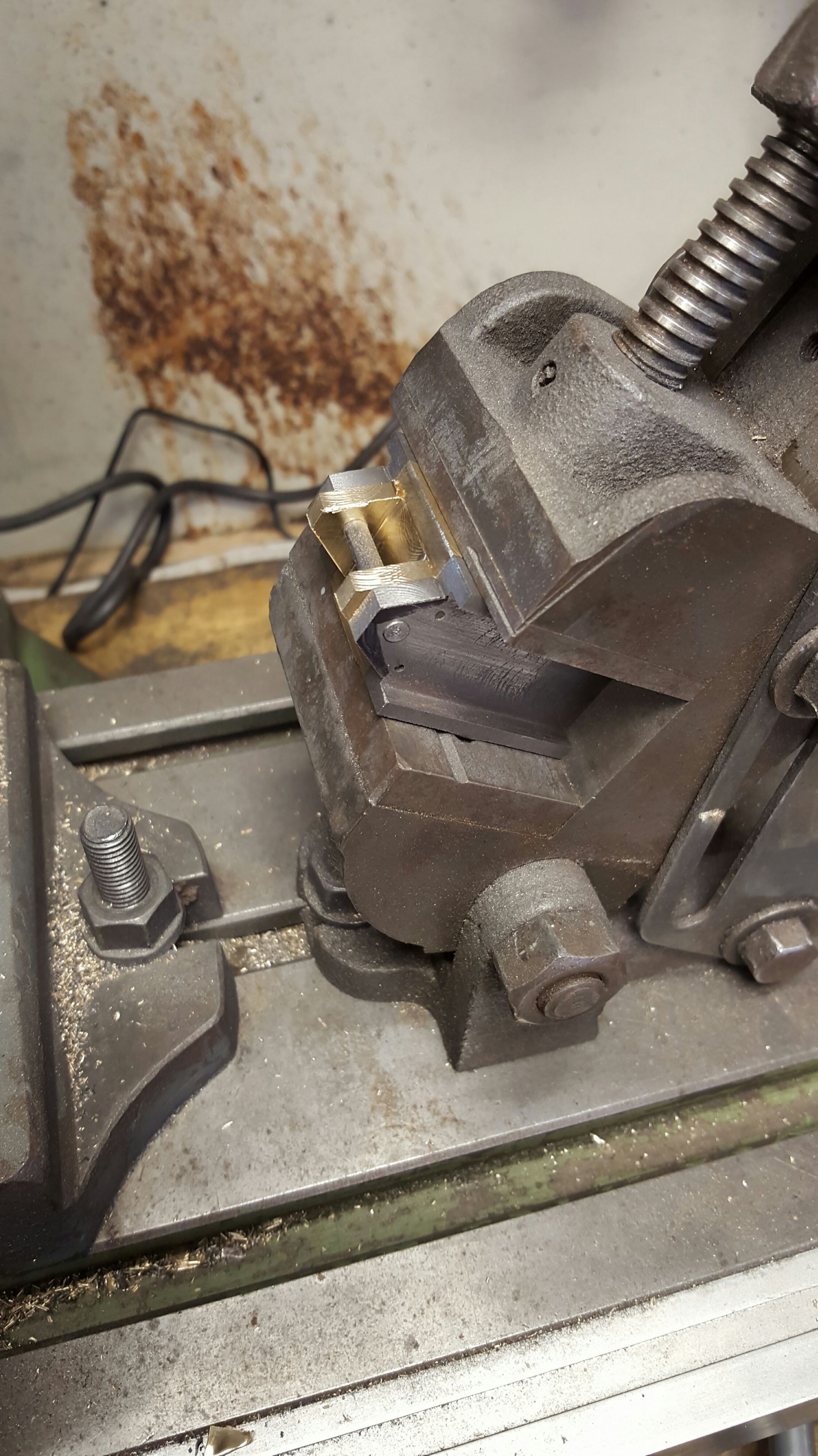
It was then back to the 4 jaw after first using a larger centre drill to enlarge the centre holes ready for being held with the tailstock for final centering of box in the chuck. No spacers needed this time now that the keeps were flush.
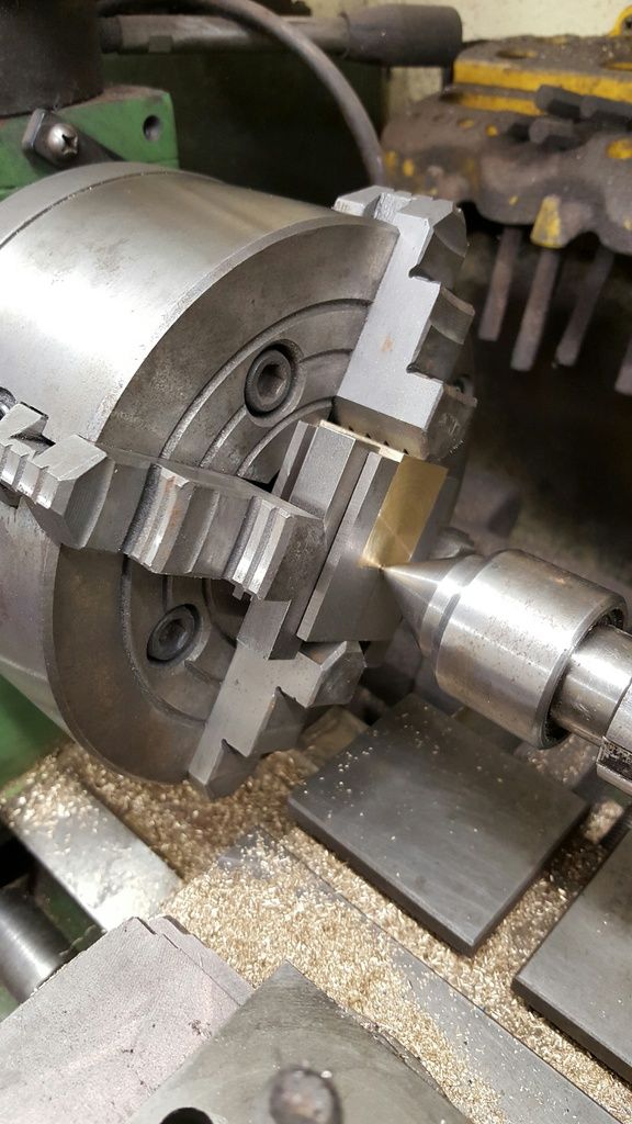
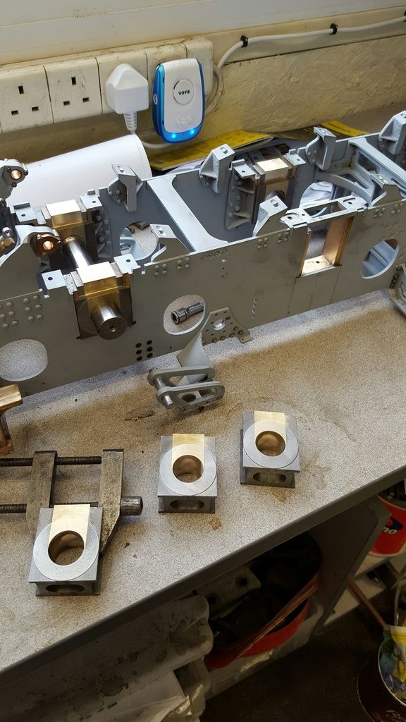
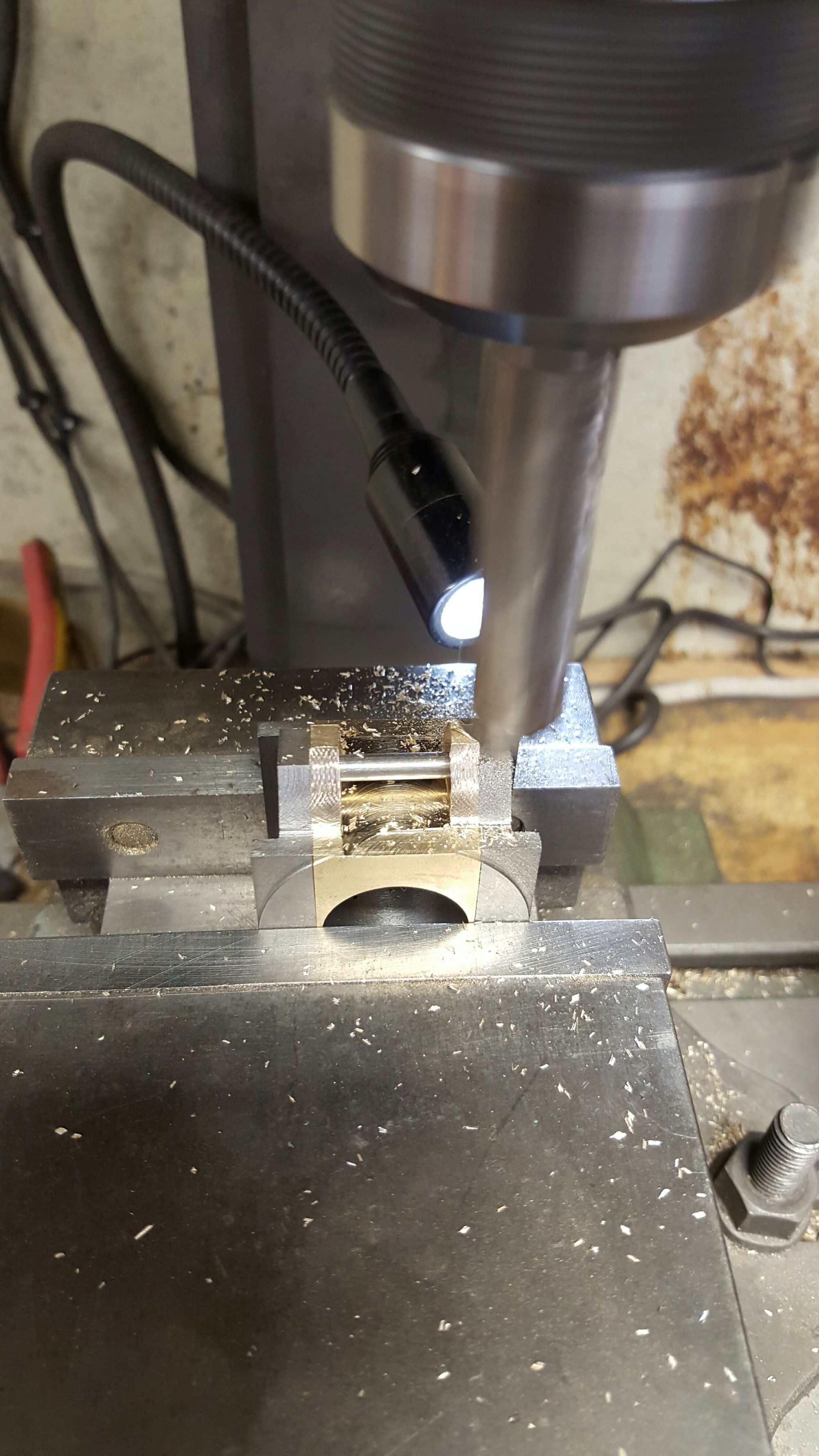
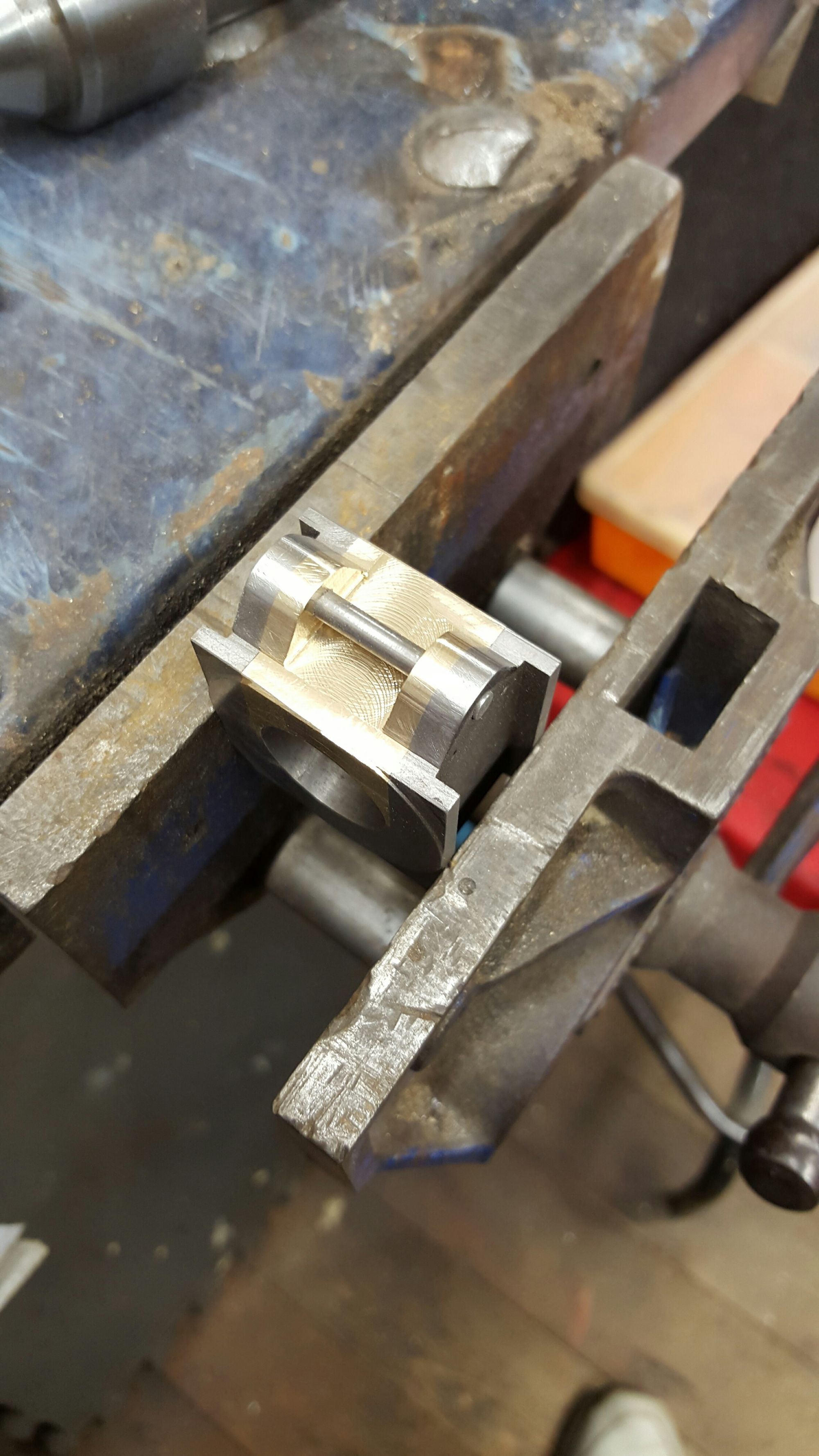
After some step drilling I bored out to the required 7/8 checking with a plug, the plug fits but it's a little tight, I have left it at this until after the boxes sat in their slots. With the axleboxes still a tight sliding fit in their slots. This keeps everything tight for now, the bores will be reamed in pairs while sitting in their slots.
And so both crank boxes are now bored, axle fits but a little tight for reason explained, when all axles are at this stage I plan to use a length of 7/8 silver steel after reaming as a lapping tool between boxes whilst fitted in the frames, this should give me the running clearance while keeping everything square, well that's the plan. I did one more check to see that things are still on track by using the set vernier to see if the distances still match, I pushed the axle in until the vernier was running parallel to avoid a false reading , all looking good so far...oh ignore the reading...it wasn't on when I first set it and guess it wasn't zero'd....the actual reading is 7.6875
NB: As it turned out I didn't need to lap the bores, the reamer alone did a great job.
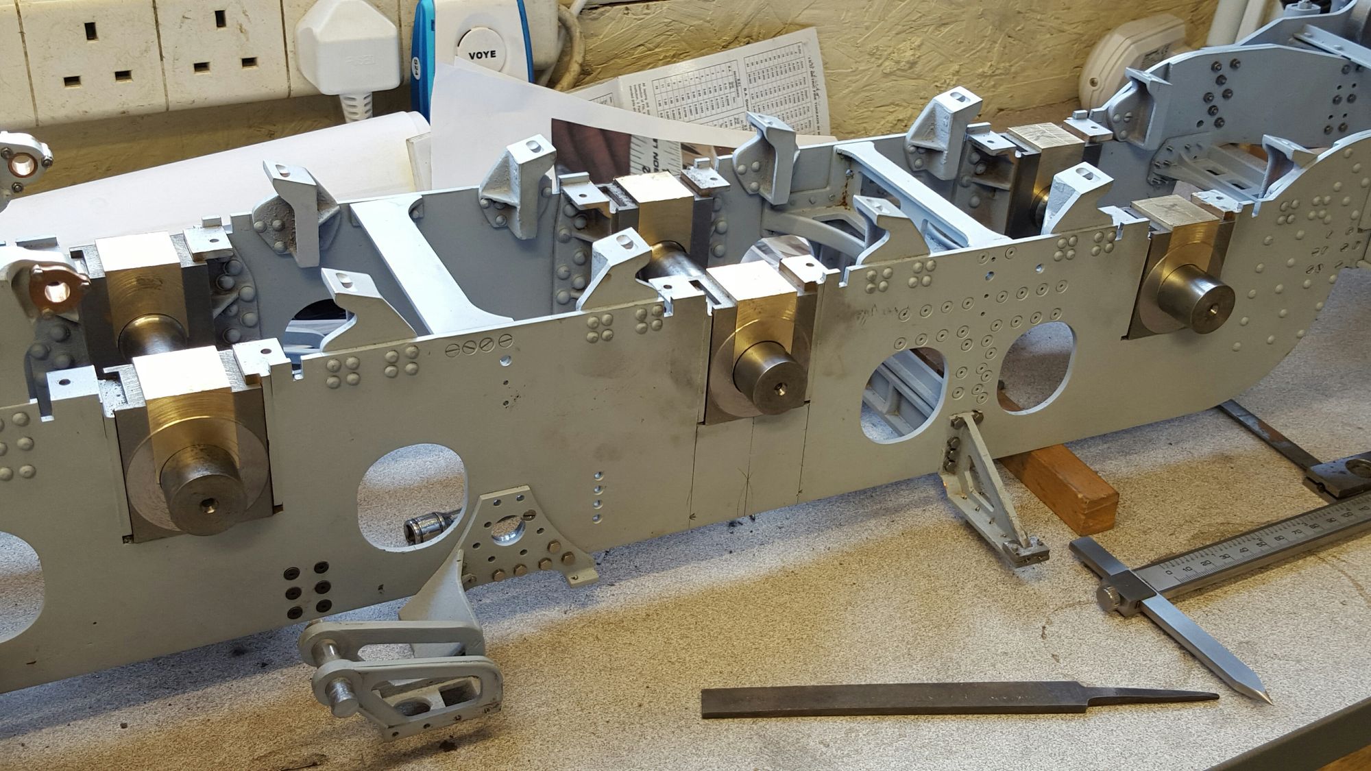
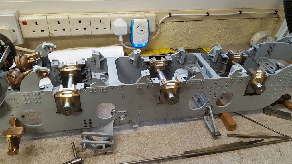
All three axleboxes have now been bored to size, I changed my plan to lap for finish as the boxes turned out in good order, any squareness discrepancy could have been sorted by lapping while in the frames, well at least that was my fall back plan. So they are now a running fit although the trailing axle is a little looser than the others But no play, just not as tight.. after running in they should/will all be the same.
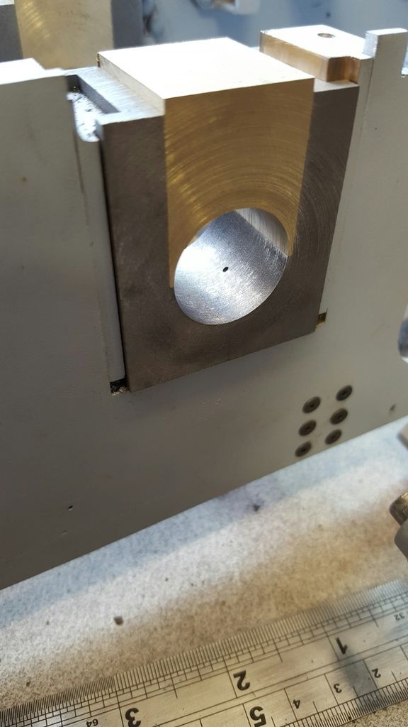
And here we have a picture to show where the oil-way breaks through the crown...
Here we see the front faces having been machined to leave a raised 1/64 centre. Each box was clocked in the 4 jaw, a suitable cutter was chosen to give the required chamfered edge and machined down until I had 1/64 depth and the 1 5/8 diameter. I did this by eye, cutting until breaking the flat edges to give a complete ring as per drawing. X axis then left set to machine the other 5 at the same setting.
After splitting the keeps from their axleboxes, next job on the list was machining the oil reservoirs in the keeps. As with the axle boxes I've taken the easy route and changed the shape, this time, to circle instead of the rectangles stipulated.
I decided to make the recesses 5/8 Dia ( largest cutter that I had at the time) and 5/32 depth as per drawing.
Having set/reg the mill I first machined the centre using a ground drill that was large enough to get rid of the material in the centre as my cutter is an end mill (first picture) , not very good for plunging...
I drilled this a little deeper than 5/32 to ensure clearance for the end mill, it will also make a nice sump central to the oil pad.
Next was the 5/8 recess for the oil pad, as it was cutting into an arc it cut fairly easily with no drama.
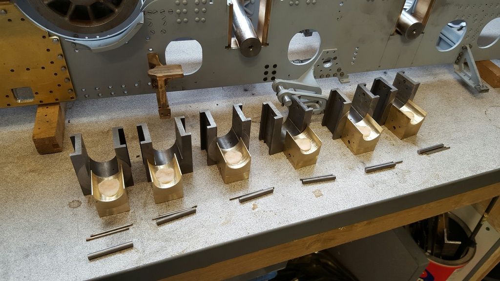
And so we now have all 6 keeps with their oil reservoirs machined and oil pads inserted, the pads are a slightly larger diameter so that they stay in the recess, they are also double sided but I doubt that would hold them alone once oiled, the way they sit in the recess should hold them fine anyway. So this picture shows the various components...so far..
I now needed to make a start on the bottom of the axle boxes/keeps, after first resetting/reg the mill I machined the front and rear faces to their correct height of 1.5625, the depth of the cut wasn't given on the drawing so I took a rough measurement directly from said drawing, the drawings are very close to scale anyway and this isn't a critical cut in as far as the depth is concerned.. rear face..
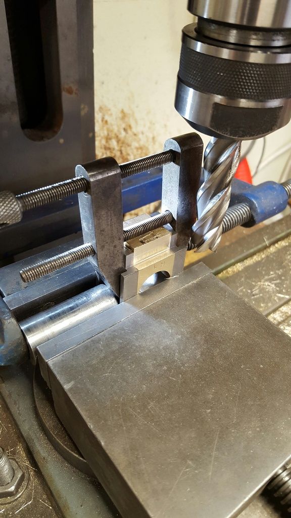
and front face...I used an engineers vice for extra security but it's unlikely that the keep would move, it's a tight fit and the 3 securing pins are in place, still better safe than sorry...
this picture was just to show state of play at this point, you can see in the foreground 3 boxes that still need machining to height with the other 3 in situ,
I have placed one of the horn stays in the above picture, in place on the middle (crank) axle to hopefully give some idea of what's next. I need 5/8 slots machined out of the keep centres (parallel with the axle) for the spring buckle to fit which in turn is held by the spring buckle pin. I then need to machine an angle from the front/rear box faces up to the buckle pin, thus creating a triangle, there's a radius to put here too, at which point the keep will finally be flush with the bottom of the axle box. . The spring buckle swings through the rectangular slot seen in the horn stay and connects to the leaf springs and their own buckle below....er there's an awful lot more to do here before we have a fully sprung chassis but at least, the axle boxes are getting close to being finished....
The next picture shows the setup for machining of the 5/8 slots....I very nearly messed up here by forgetting to remove the buckle pins...twice?...lol luckily I realised before machining too deep... after the second bout of forgetfulness, I removed all buckle pins just in case...:)
We now see all of the boxes at the same state.. a little filing to clean up and the 5/32 reamer to clear the pin holes was all that was needed to get to this point,
This update is the conclusion for the axle boxes, there will be one other exercise to do later which is relieving of the slots to allow the axles to tilt but for all other purposes, the boxes are finished.
6 pictures for this last axle box update, first the marking out of the angles on the bottom of the boxes/keeps. The bottom radius is drawn as 3/16 so I turned up a small button at that radius, drilled/reamed 5/32 to fit on the buckle pin and be ascribed around after first marking each box slot with a marker pen. I then ascribed lines from each corner to the ascribed arc as a guide for machining.
Next was to set up the angle vice to machine the angles, I did one side in stages until happy with depth and then machined the others to that setting, I then needed to do a second pass on the front face as this needs to be a little deeper due to the 1/64 raised front which makes the pin slightly off centre...hope that makes sense?
I then machined off the keep tails to make profiling a little easier, you may remember that these were deliberately left oversize so that the keep was held tight in the axle box for boring.
Next was to profile the tips to the 3/16 radius, I took the excess off with the sanding table and finished using a file by hand, I also put a small radius on to the corners of each box.
And here with have a completed axle box, I only radius-ed the front corners seeing no need for the rears, Don did a great job on drawing these as they are very close to full size in both looks,operation and lubrication methods.
Last picture for this entry to show all boxes in situ and also a short explanation of their workings.... I have set the 3 axles at different heights, leading coupling axle at full depression ( for the slot, not operating depression) crank axle is set at I hope normal running height, I took this off the drawing so it should be pretty close and lastly the trailing coupled axle at full bounce (for want of a better word), note that this means the bottom of the box penetrates the horn stay slot itself, quite an intricate affair.
Now according to info on Gresley's pacific's they have about 1 1/2" verticle travel of the axle boxes, reducing this to 5" gauge works out just over 1/8, not enough for model tracks, the actual movement of the model is currently around 5/16th, I haven't checked what Don suggests yet but if more is needed this can be remedied.