
Onto the axleboxes, Don has followed full size very closely without going to far overboard, such as no machined pattern on the slot faces or some of the smaller parts. His design does look the part though and ,of course, is a 'split box' design.
I will try to cover how I'll tackled these little beauties in more detail than usual, Although simple machining setups they are very involved in design which involved a fair bit of work and time to complete, there will be other details listed after this entry as I didn't do everything in one hit.
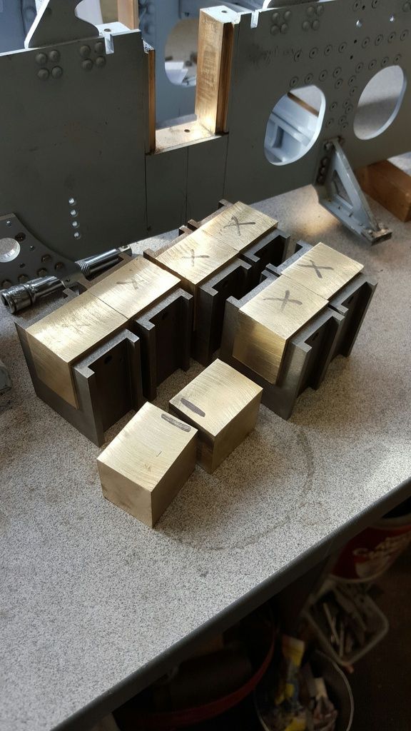
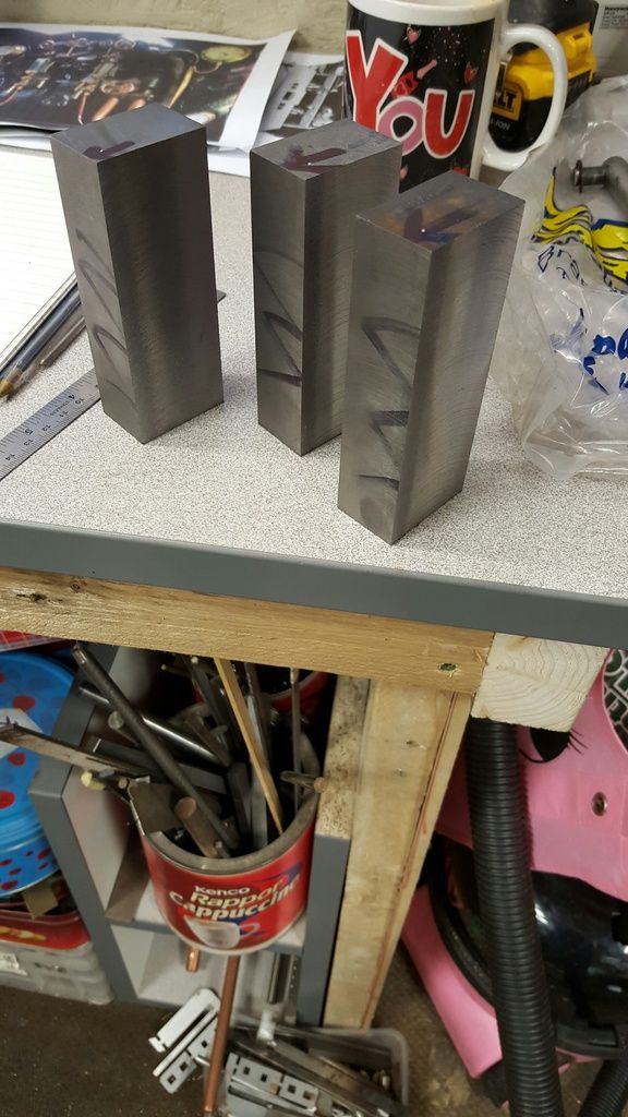
Ok so first a small error in Don's words, nothing major and to be honest you could probably get away with it but best to get these things right. Don states to first machine a stick of gunmetal or cast iron to a size of 1.5312 x 1.0468, you need about 12" in length, however this is forgetting that the front flange as shown on the drawing is 1.6250 wide and this is a nice fit between the horn outer tabs, it's the rear that is 1.5312. Therefore I followed the drawing and machined to the larger size, I'll machine the rear to size once all other machining has been completed. I had a 13" length of CI that I had bought a few years back and first cut it into 3 parts, this way I could hold each securely in the machine vice with each length representing two boxes, IE one set. First picture shows the CI stick in 3 parts.
Now the CI stick is much bigger than needed but it was relatively cheap so I made do even knowing that it would involve an awful lot of machining, alas I didn't have a suitable tool that can cut through a 4" length of 2" thick CI and my days of doing such things by hand are long gone so I was in for a messy time consuming exercise.
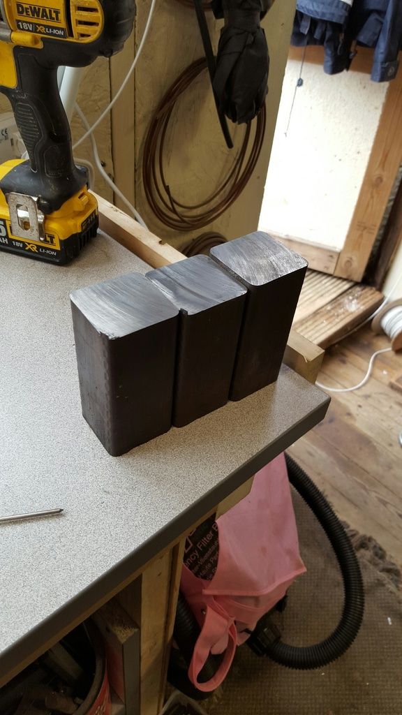
The next picture to give some idea of how much I have to machine when compared to the finished sticks shown later. I used a 3" facemill which although a little large for my mill cut without effort, after first shaving a small amout to get all square I was able to make 40 thou cuts at approx 2" per minute using 500+rpm, the machine seemed to like this cut which was good enough for me. I used no cutting fluid for this job, CI being a little self lubricant but more to the point with so much CI filings's flying around ( I covered up what I could) everything would have rusted up using a water soluble cutting fluid.
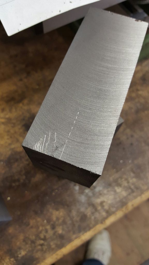
Here is one of the risks when using CI, a flaw discovered during machining, as the cutter passed over this section lumps of metal fell out, luckily it was only for about 1/4" depth and I had noticed it before machining down the opposite side too far, this flaw was only found on one piece, I suspect it was one end that hadn't cooled properly. For those building this loco I'd follow Reeves recommendation when choosing between GM or CI for the cylinders, they have a lot of problems casting in CI and you'll find unusually that they charge more for CI cylinders than GM due to the amount of rejects encountered during casting and from later machining. This will hopefully, be better understood when we get to the cylinders.
And so we have 3 sticks machined to size ready for the slots, as you can see they are a lot smaller now....I marked each face after final cut to take away the risk of inserting the stick the wrong way by mistake, just me being extra cautious for the following set-ups...
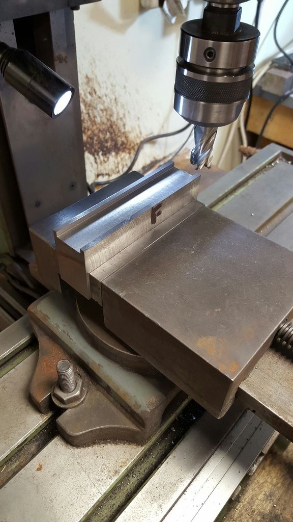
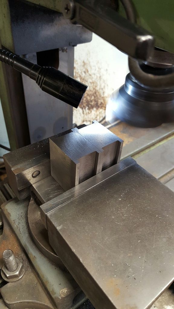
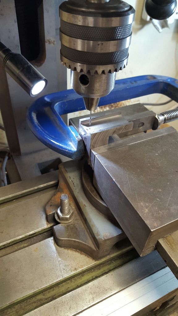
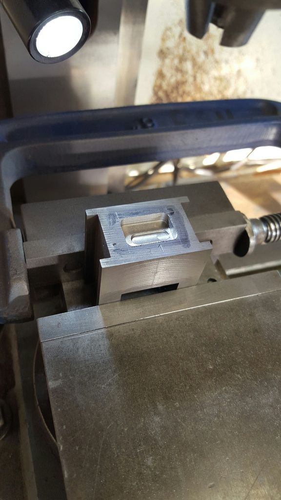
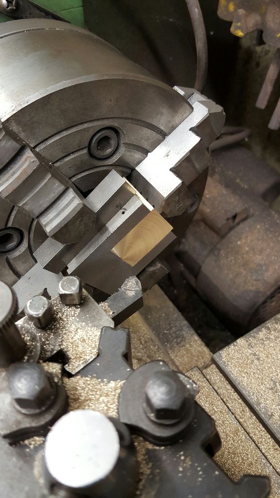
Here we have one slot close to size, I chose to do things a little differently to Don who suggests to machine one slot to size, flip over 180 degrees and machine the next slot close to size, checking fit slowly machining away until happy, to me this risks an error as you may be pushing the axle box off center or at least that's how I saw it. I therefore machined both sides undersized and checked for fit taking equal amounts of each side until happy. Notes were made of the DRO settings for the other 2 sticks. For the flanges I kept the front flange to size and machined from the back until the box was a sliding fit for obvious reasons.
Once happy with the fit (driving axle) I parted the boxes on the chop saw and slid them in place, they were tight which is what I wanted, you could push them up and down but not easily, however after a few motions the tougher cast iron soon lapped the gunmetal horns to size which had been left approx 1 thou over. I read through Don's words and noted no notes for any side play, how much rock was required which will be dealt with later by relieving the ends of the slots. Certainly the drawings suggest that there isn't any side play (float), I may just wait and see how trials go on my club's tightest curve and perhaps take a little of the driving wheel flange if required, either way I won't worry about it for now. With the boxes snug in their slots it will make ensuring that the axle centres are correct a lot easier, I'll cover my planned method when I get there.Note that the boxes will be shorter than shown here when completed, the extra metal is for the pin hinges that are integral with the box.
NB: I had assumed when originally writing these notes that there may have been some 'side play' on the main drivers to allow for tight bends just as there is on the tender. What I had forgotten was that these need to be fixed (relatively) for the motion, unlike the tender axles.
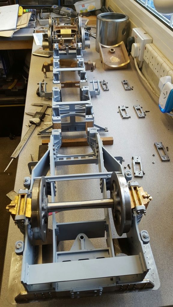
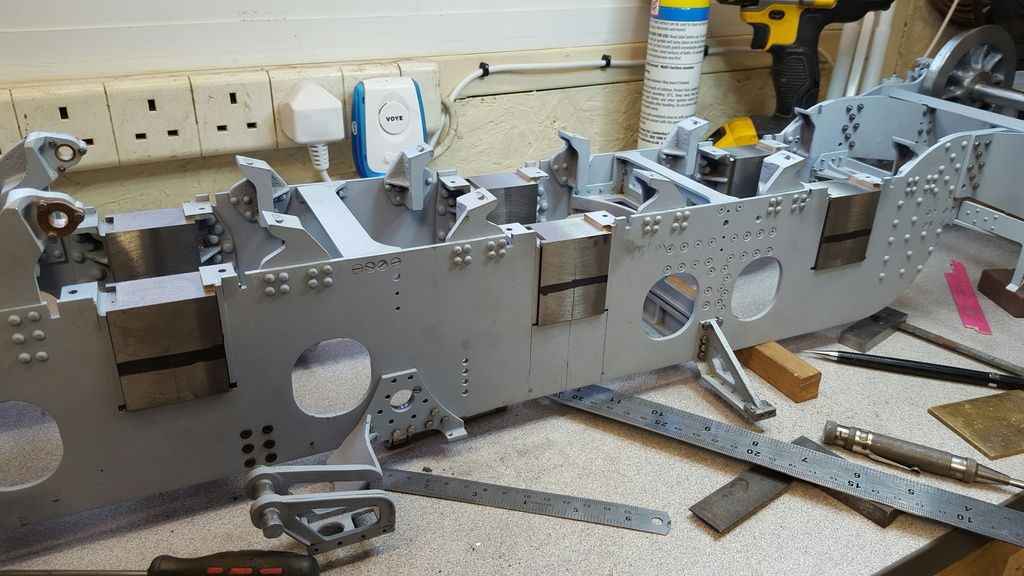
I include this image so we can see the underside of the chassis to date, not a view often seen so just included for interest....
The next four pictures don't look much but IMHO are a critical step in trying to achieve a good running locomotive and so I will show how things are going, this being the spacing between the axles.
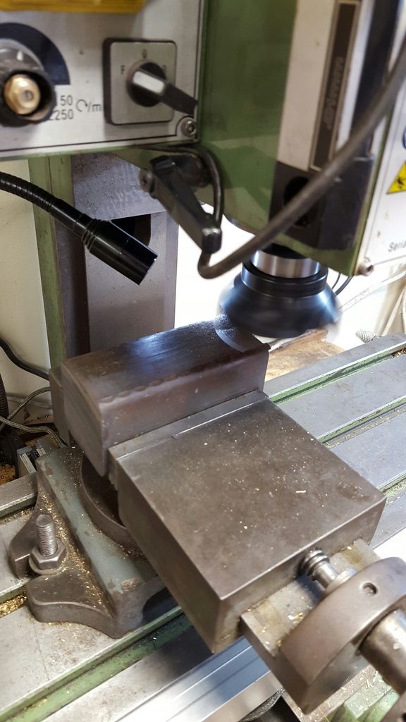
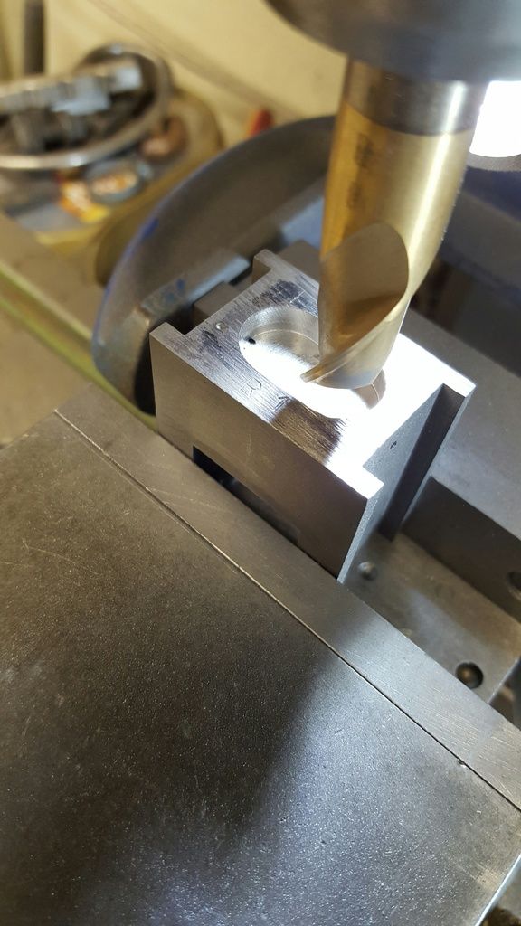
First though I needed to machine the axleboxes down close to their final height of 1.8750, I left them at 1.8950 as they have a triangular shape at the bottom where a pin holds the spring swivel in place and this needs profiling later to a rounded shape. I have a lot of different setups to do on both the mill and lathe for which I need the boxes square before I can machine the bottom shape so it will have to wait for now, the picture shows the final cut being taken for the trailing axleboxes. To unsure all boxes are the same I set the cutter height and then machined each set of boxes together, I have done this throughout the various machining processes involved, it takes extra time but I prefer to do things this way to ensure all dimensions are exactly the same for each.
After all of the boxes had been lapped for a good close fit between the horns, I then needed to check how things were going in regards to their accuracy, a tense moment even if I had done all that I could to ensure they were as planned, there's always that question in the back of your head 'is it right'?...well there is for me...
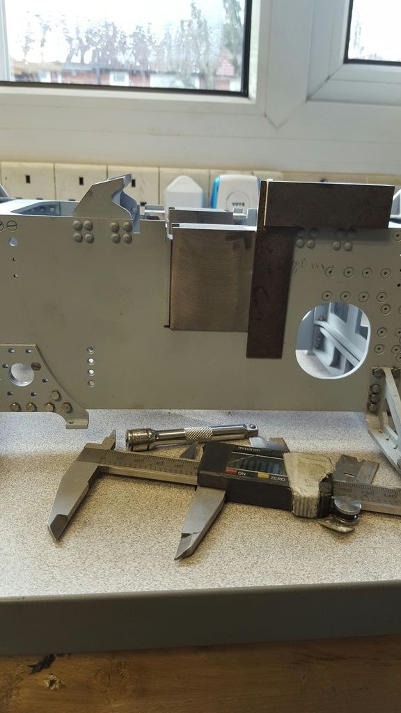
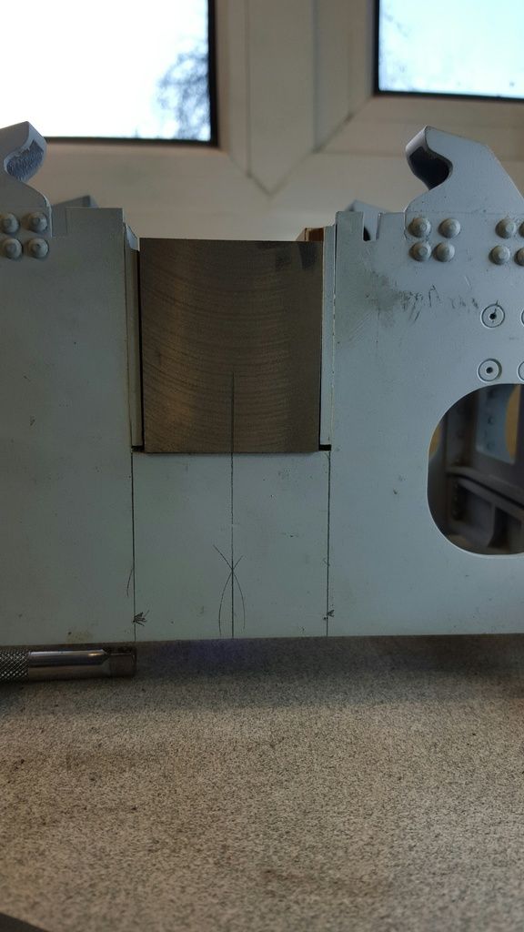
I divided the frame slot for the crank axle and marked it accordingly, I then marked each axlebox the same and fitted them to check as shown in the picture, looking good even if I say so myself. I then did the same with all boxes in the same crank position, I was very relieved to see that no matter which box I fitted into whichever pair of horns they were all central, this is a great step forward in my confidence that I can get the motion running nice and smoothly, well as long as I make the other components correctly that is....
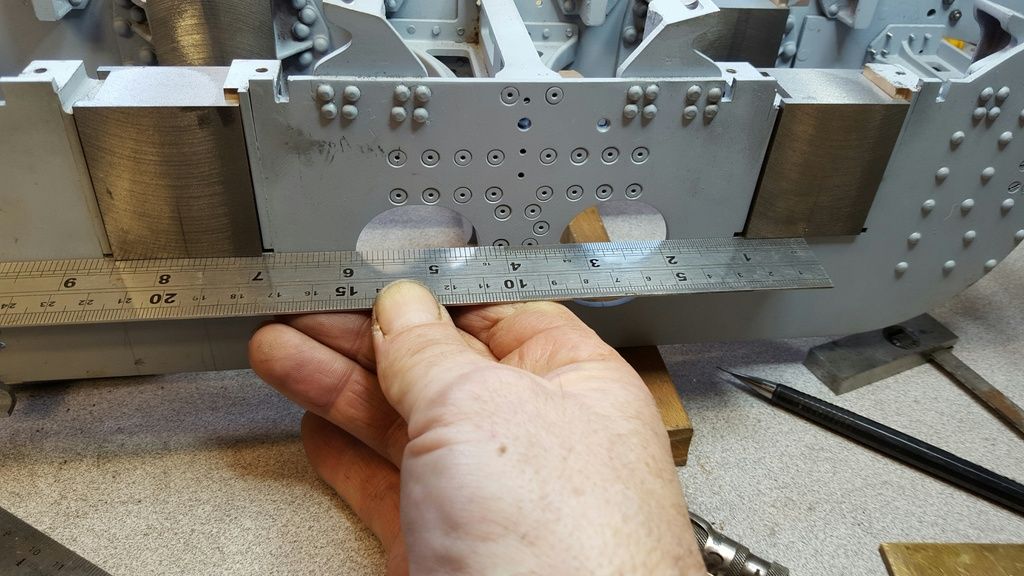
Next critical check was the axle spacing, they should be fine but it's always wise to check before machining the boxes for their keeps, if there had been any discrepancy I could have offset the box centres a little to compensate but no need as they are fine, picture shows a rule showing the correct spacing of 7 11/16...
This picture shows the boxes marked ready for having the keep slot machined...
So, I'm both happy and relieved with the days progress, I have set up the crank axle boxes ready for machining the next day. Although this would take some time, at least I knew that things were going to plan and I could relax a little. Although things look good I'll still double check everything as I progress to the boring stage, once the keeps are fitted I'll mark out the crank axle centre, fit all boxes back into the frames and using a digital point to point vernier scribe the centre's for both leading and trailing axles at 7.6875, they should match the lines drawn but you can't be completely sure with just a rule, things looked good though.
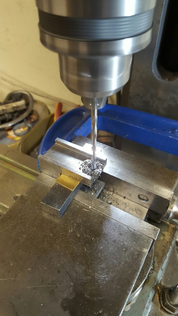
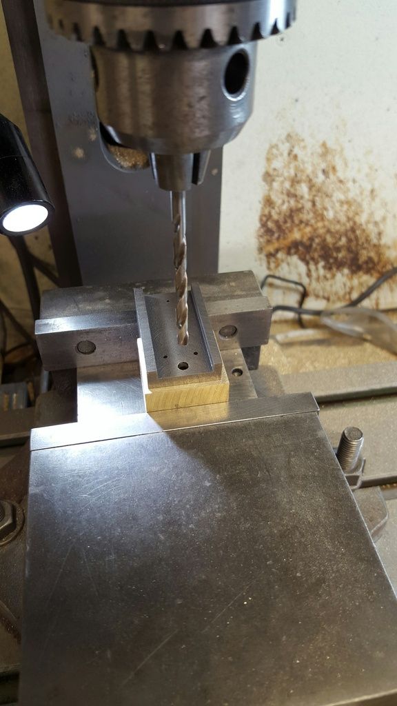
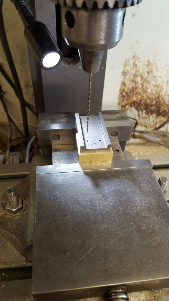
Axleboxes continued...having finished fitting the boxes to their horns I moved on to the oil-ways and their reservoir. Using a large G clamp as a register, in turn I held each box for drilling the central oil-way that lubricates the horns as shown in this first photo...
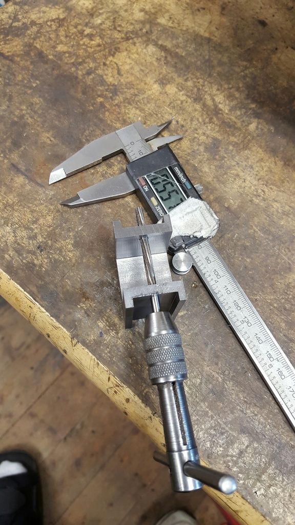
With the two No.57 oil-ways drilled I moved on to the 5/32 spring buckle pin holes as these are on the same central line, I drilled right through both slots using packing to stop any flexing of the job..
then reamed the hole to size...ignore the vernier...it just happened to be in the photo...
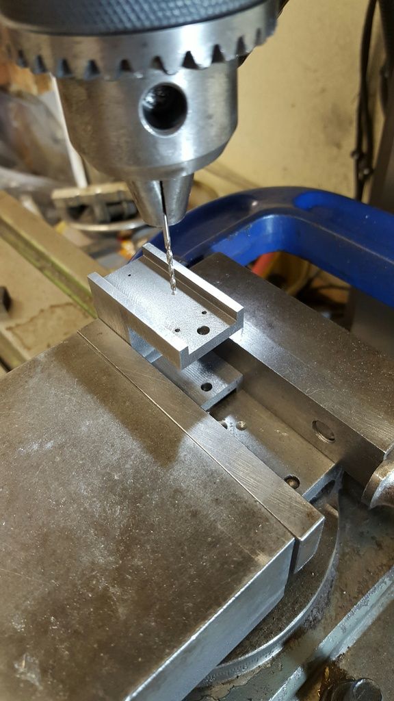
Last drilling job in this setup was the 1/16th holes for the keep retaining pins, at first I thought of trying to drill these straight through like the spring buckle pins but being so small there would most likely be some deflection and also I had no guarantee with the equipment to hand that if I drilled the holes separately through both sides that they would match perfectly the keeps once drilled. Therefore i decided to just drill on one side, when the keeps are machined for a tight fit in the slots I'll drill through these two reference holes, through the brass keep and out the other side of the box, my reasoning being that if any deflection does occur it won't effect the pinning of the keeps being drilled as one...hope that makes sense...
Next was to machine the oil reservoirs on top of each box, I began following the drawing machining a rectangle using a 6 mm cutter ( size dictated by corner radius) and spent some time getting to this next picture which is still under size before deciding this was taking too long and unnecessary for the job in hand, also here I'm only about half way to the required depth of 0.218 needed to meet the oil-ways.
So a change of plan, using a 14 mm cutter and registering the piece, once setup I could do the job in just 4 passes, although the slot is a fraction wider it's probably a little smaller in capacity due to the radius'd ends but nothing to effect it's purpose and will never be seen. You can just see one of the oil-way holes breaking through as it should.
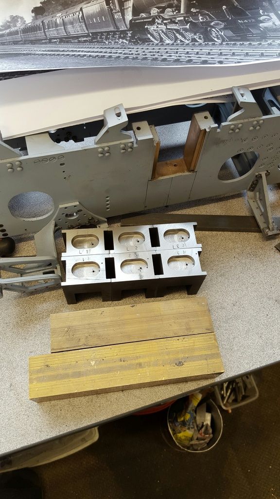
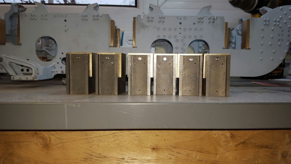
this was the last picture for that particular day, it shows the six boxes awaiting their keeps, note the hole drilled down through the top to lubricate the axle journal, these are handed so that each journal is fed to the rear of it's crown. The two sticks of brass in the foreground is the next job, these will be the keeps, first job to machine them to be a tight fit in the keep slots, I guess I'm about half way doing these axleboxes at this stage
moving on with the axleboxes, I was now busy with the keeps.. I won't bore you all with pictures of me machining yet more sticks of metal so the first picture jumps straight to the keep blocks having been machined to size for the axlebox slots. There was a good few hours of work getting to this stage, first machining each stick to within a couple of thou of the slots, then cutting the sticks into individual pieces (oversize for now), filing any machine marks from the slots and finally lapping each keep face until it was a tight fit in it's allotted slot. The two extra brass blocks are spares...

On to the drilling of both the spring buckle and keep retaining pins, first up being the larger buckle pin which is simple enough or should I say less nerve racking than the 1/16th keep pins. A point to note here is why I left the keeps oversize for both height and width, in this case the height. I wanted to ensure that the keep was held tight against the top of the slot and leaving the keep oversize and setup this way around in the machine vice I could do this.
Next was the keep pins and this was the nerve racking bit...not so much that there's anything difficult in drilling holes with a long series bit, no, more the fact of the consequences of said bit snapping during the operation, luckily such evil did not visit me this day....
Having drilled all of the buckle pin holes, I made up the 5/32 pins and fitted each before doing this stage.
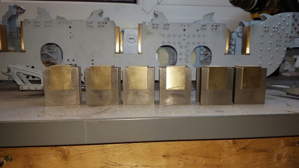
two pictures to show progress...first the boxes with their keeps showing the pins fitted
and then a view from the front, I'm very happy to have got a nice fit of keeps to boxes, should make the rest of these parts pretty straight forward as long as I get the boring right...
The next job will be to set these up in the four jaw and machine the widths down to match the boxes, once this is done I can plot out the axle centres, starting with the all important crank and then plotting from that point the leading and trailing axles.
A few more pictures than usual for this stage as I try to get on with describing how I do these axleboxes.
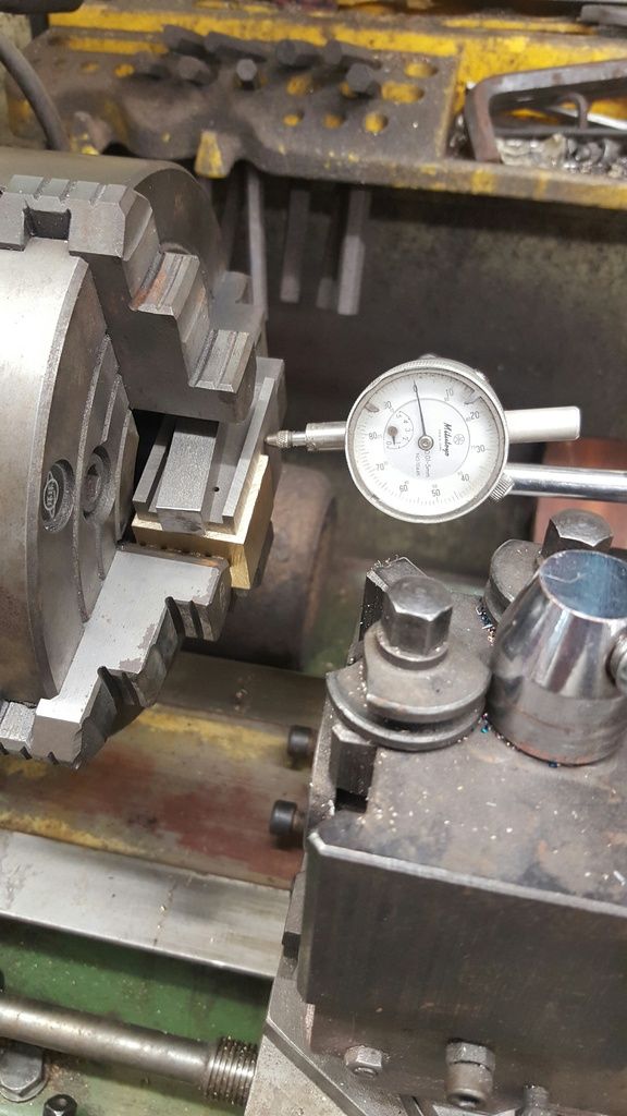
First job was to machine the keeps down to the same width as the boxes, I did the rears first using packing to give me a flat base to position against the chuck face, square bar to fit in the slots and set by eye for centre as this wasn't important for this stage, I clocked the rear face as shown in the next picture to ensure all was square, rear packing was removed for safety once the box was held tight.
It was straight forward machining to get the keeps to size...rear face
Part 2 will cover the all important boring of the axleboxes.