NB: I loved making these little things, very prototypical
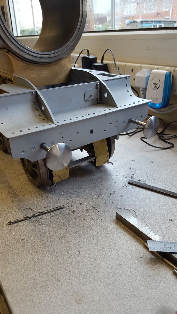
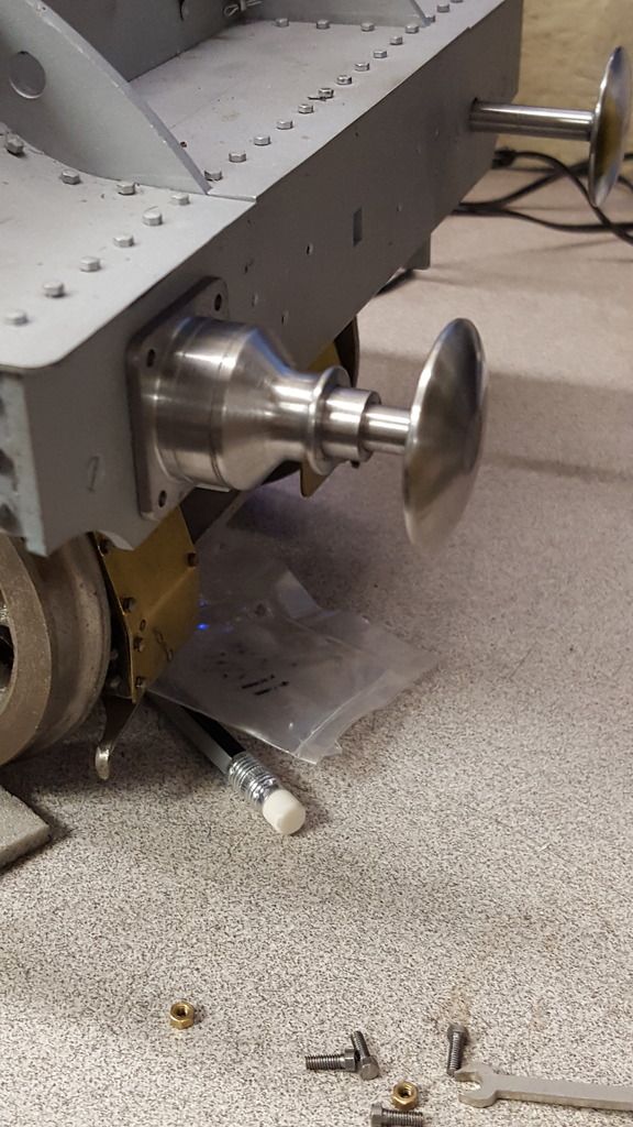
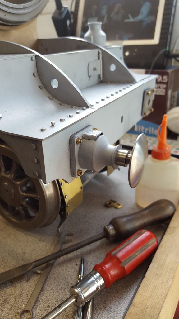
After finishing the crank, I looked at the chassis to decide what to tackle next.. there's so much left to do ( I reckon that I'm only about 40% into this build) that it's very daunting when considering just how much work is left to do. Brakes will involve a fair bit, suspension still has a long way to go and as for the motion?..well that's a lot of work on it's own. anyway while pondering over this the one thing that did stand out as missing is the front buffers and so these are what I'll concentrate on for now. I had in fact already completed the more involved part of this area , that being the spring housings themselves so it did make sense to continue where I had left off some time ago now.
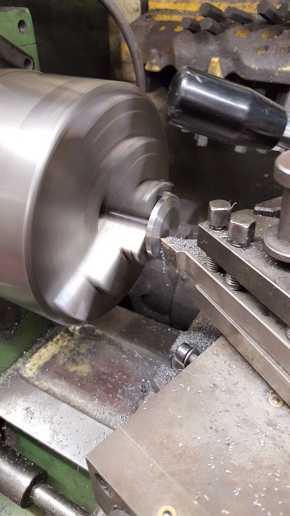
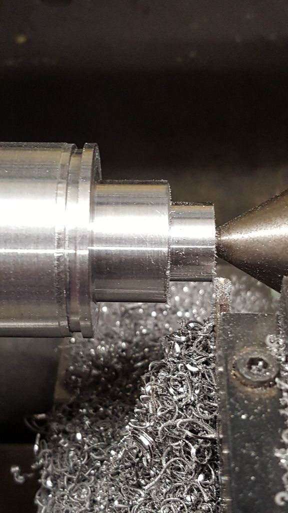
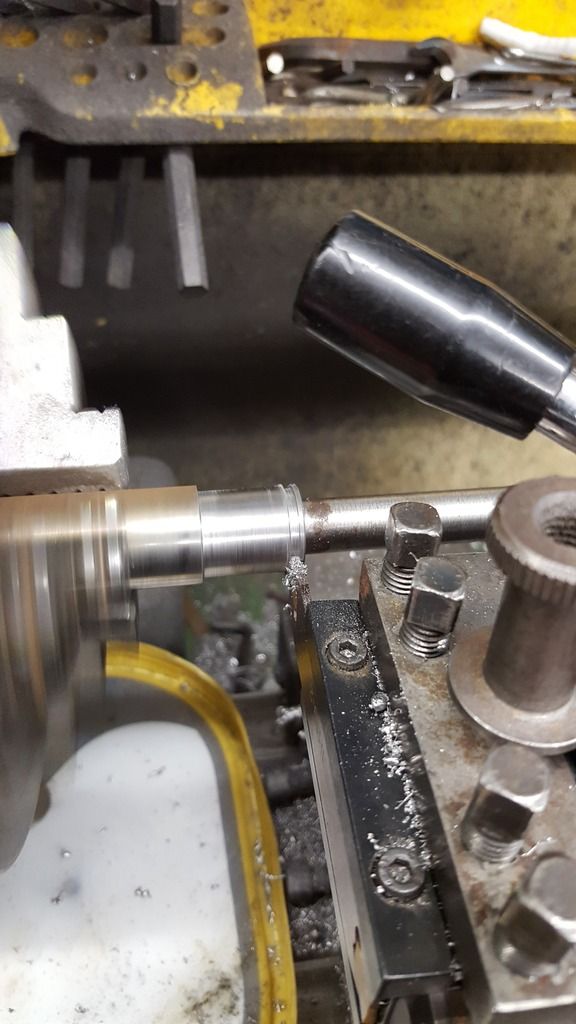
I have started with the buffer heads as I had the material to hand, in fact, I bought this at the last Midlands ME , so it's about time that I got on with them. First I had to decide if I was going to add greatly to my swarf bin by machining from solid or whether to machine the heads and shanks separately, I took the later route. I did the shanks first and the first picture shows the rear part that fits into the housing, this thinner section is what holds the rubber and steel washers that form the resistance to the operation of the buffers, so no springs here, unlike the tender buffers. The shanks start life as a length of 5/16 BMS bar, the rear section is turned down to a diameter of 9/64 over a length of 1 9/16, there is a small spigot on the end and a 1/4 length 4 BA thread. as seen here.
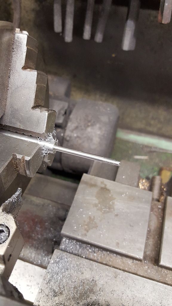
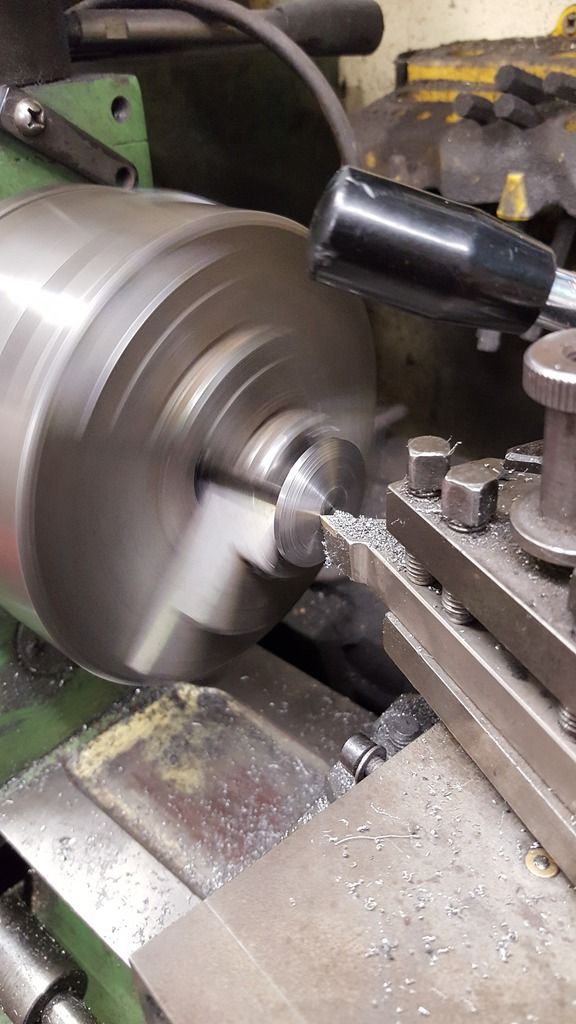
We next step up to 17/64 over a length of 1 11/16
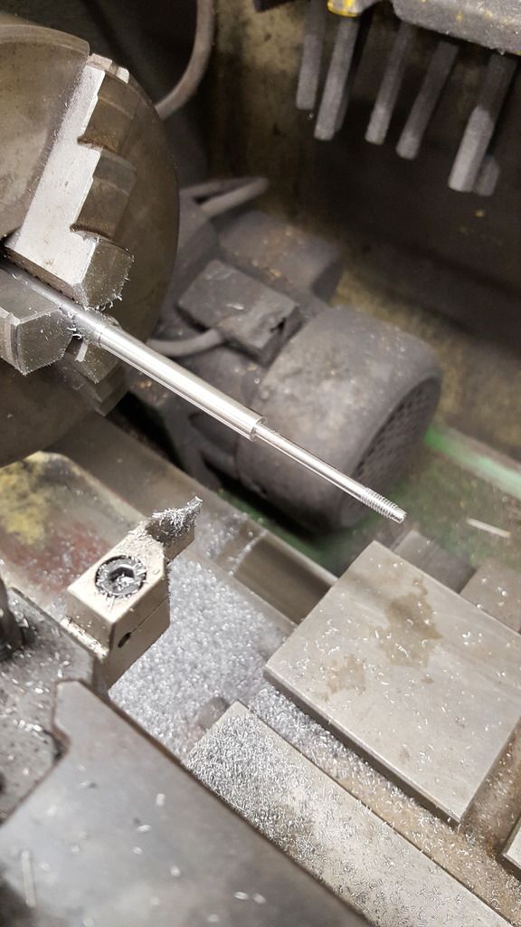
Here are the finished buffer shanks, note the extra part on the ends, this is where I have modified and added a short length of 1 BA thread that will screw into the heads themselves, the threads will be shortened to fit the heads once they are done. The big lump in view is the material for said heads.
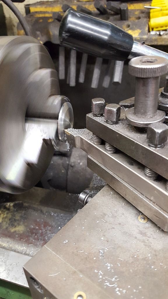
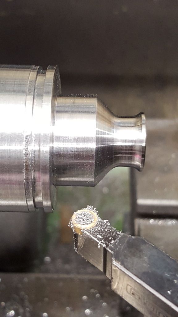
Having cut down the stock to a more manageable length it was turned down to the 1 21/64 required and was then faced at 8 degrees for the rear of the buffer head, note that I have left a flat section in the middle for the shank to sit against, this also gives a little more meat to the head for the shank thread to screw into. Last job for this picture was to start parting off at 3/16 which is the heads overall thickness ,not including the radius where the shank screws in.
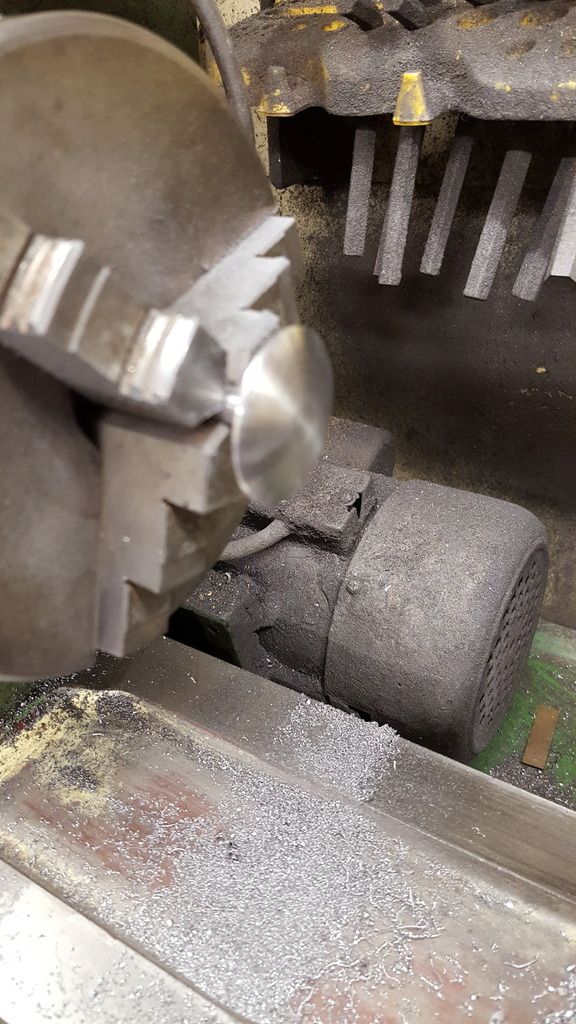
The head was then drilled and tapped 1 BA to match the shank (being careful not to go too deep), the shank was then fitted using Loctite 638. To ensure that the shank remained central while curing I used the drill chuck that loosely held it in line, this was me being careful which such a short thread. Now Don states to braze the two parts together, I decided to go the loctite route as these buffers are pretty delicate in comparison to the tender's, they could withstand a fairly hefty bang but these with such a fine shank are less likely too. By bonding them instead of brazing, if they did ever get severely damaged I could just replace the shank (most likely part to suffer) and reuse the head. After around 10 minutes ( enough for initial curing) I parted off the buffer.
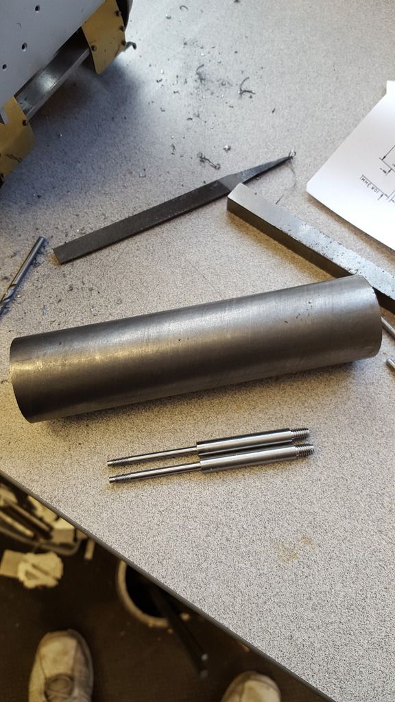
And so we have two partially machined buffers, I placed them in their positions and left overnight to cure fully before machining the radius on the front face, that even bigger lump in the picture is what my son kindly dropped off when I discovered that I had no material big enough to machine the buffer stocks, this was the smallest scrap length that he had, it's 60 mm and I needed 42 mm so a fair bit of turning coming up over the next few days....
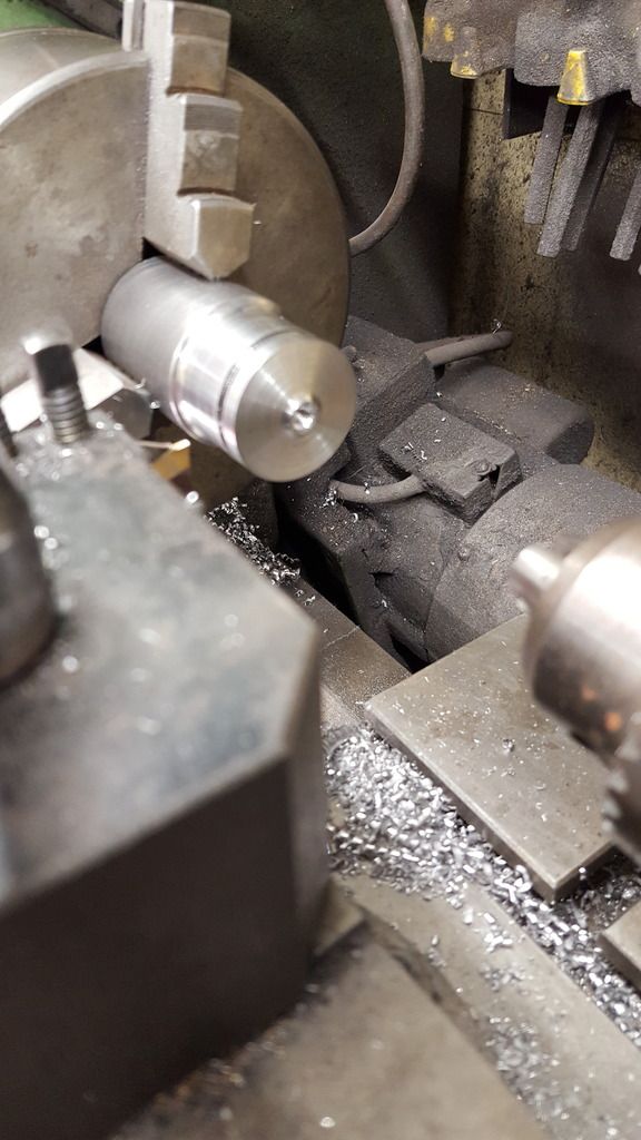
So a fresh day and back to the grind, I have covered this part with more pictures than usual as the question of 'how did you machine the buffer heads' seems to come up a lot. Some will remember that for the tender I used the 'slack' cross slide method and measured bar resting between headstock and saddle trick, this time around I decided to go purely by eye.
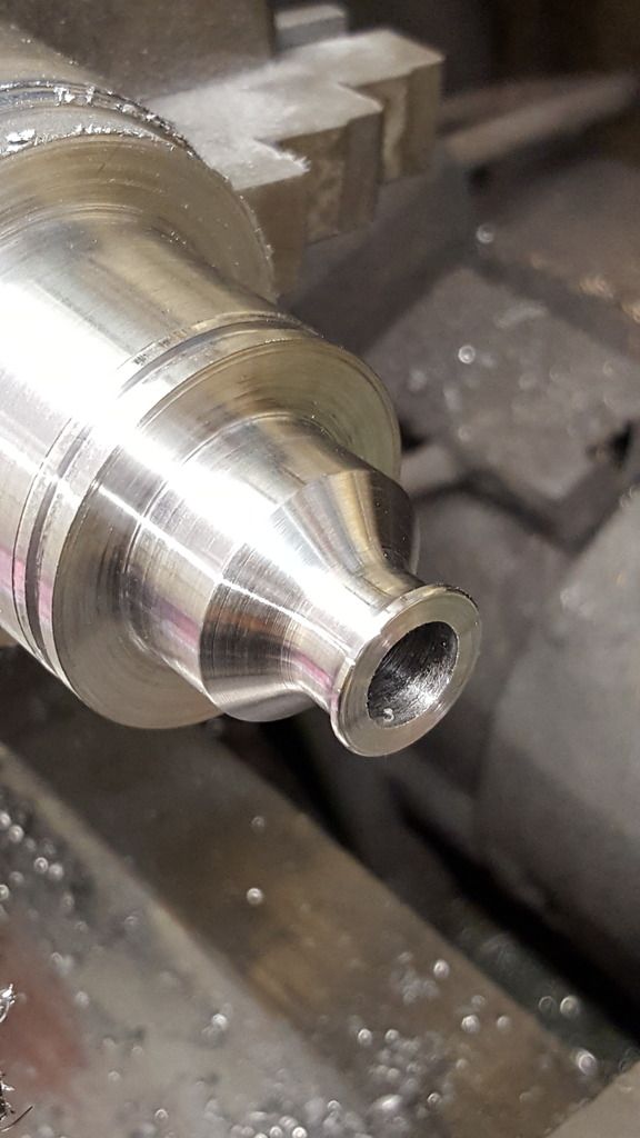
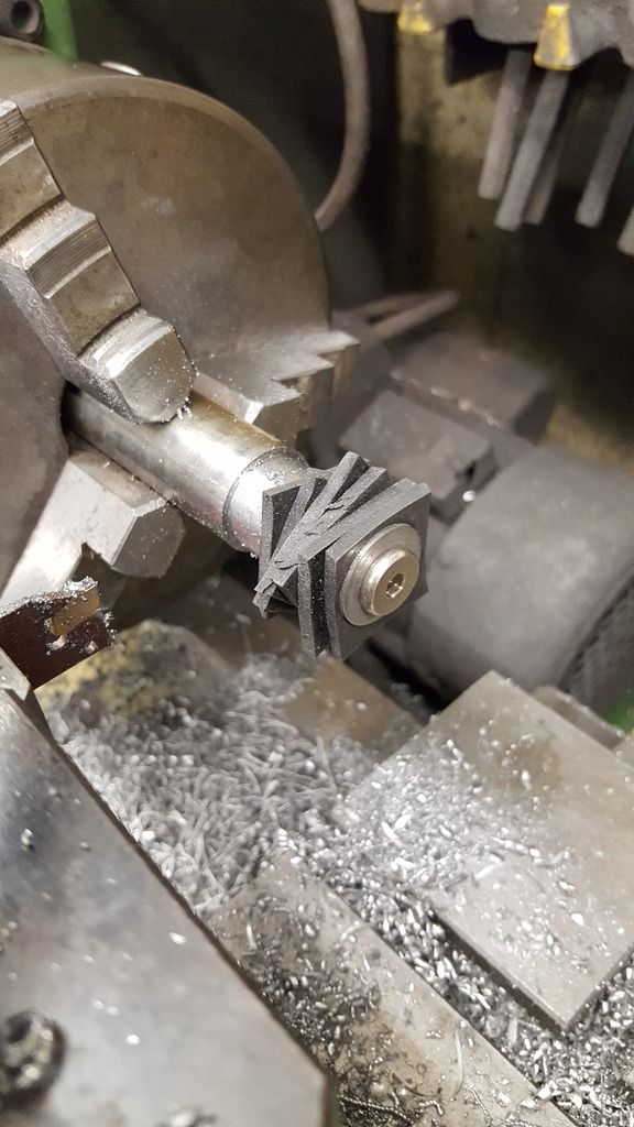
With the shank fully cured to the head and now held in the chuck I first turned down the middle of the face at an angle of 8 degrees to match the rear face, I did this in stages alternating between the two buffers, a method I used throughout the machining of the two buffer front faces.
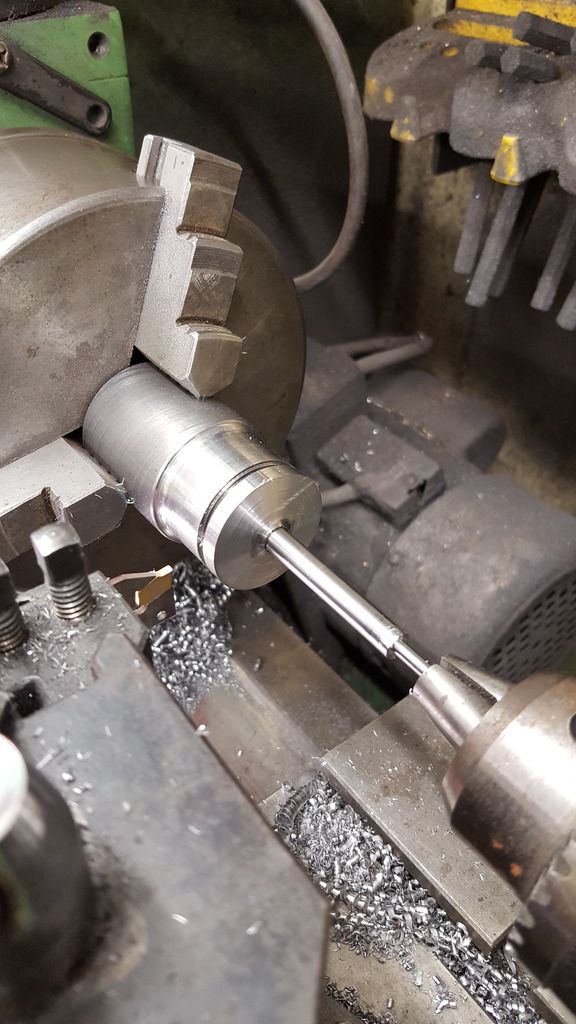
I next reduced the angle to 4 degrees and machined the inner section of the face, note I left a flat part in the centre.
I then took the angle out to around 20 degrees and machined the outer edge. Something to note here is that on the early photo's of 4472's buffers she had a flat outer edge which can be clearly seen, this seems to have disappeared to a more uniformed curve (as she is today) in the mid 30's perhaps made during her other small changes in 1935. She certainly doesn't have it in a photo for 1936 and so for my chosen era of 1938, I have omitted these flat outer edges.
The rest was done by hand with files and paper, first, a radius was filed onto both front and rear outer edges, then the high points were filed off to give a curve which was finished with paper and then sanding sponges of various grades until nice and smooth. It took less time than it might sound. apologies for the quality of the picture..
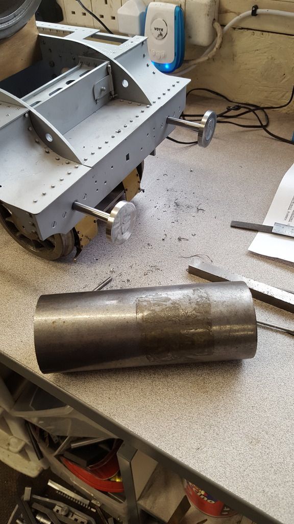
Thus the buffers are finished and shown here back in their positions
Moving on to the stocks, at the time I wasn't going to do this update yet but having looked closer at the drawings and realising that the design is a lot more involved than I had first thought. Such as it's double telescopic having an internal sleeve with rubber dampers and their associated steel discs in both the housing and the stocks? a mixture of ten for the stocks and 26 for the housings. So I best get the description of the stocks out the way now.
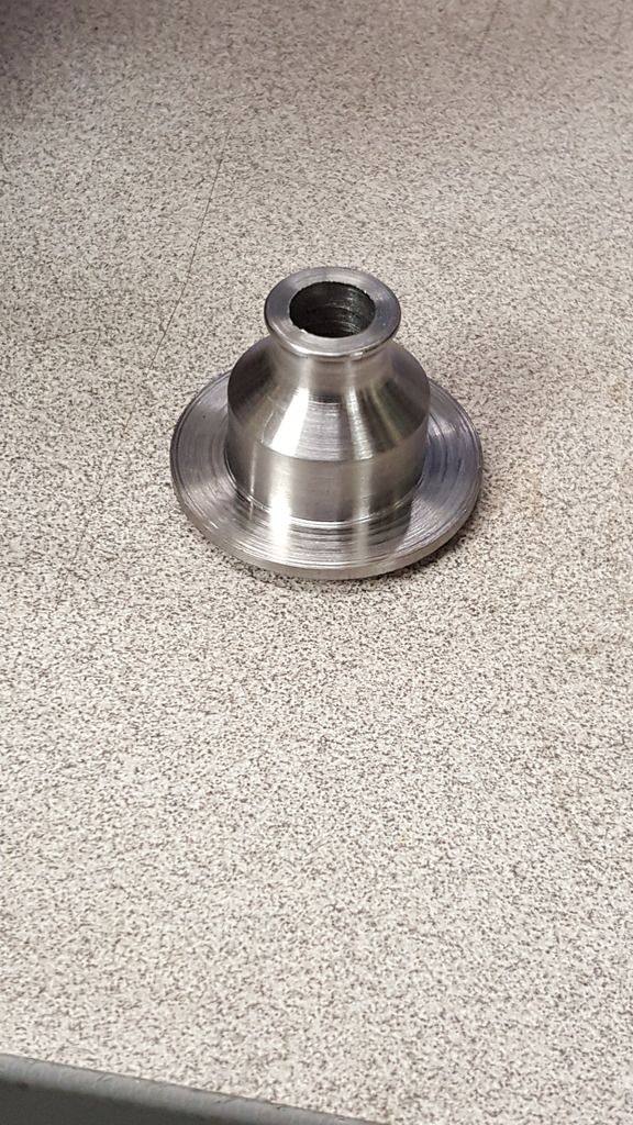
The stocks are pretty little things but they sure do involve a lot of machining, especially when the steel bar that I've used is so much wider than required, so after creating a lot of swarf to get close to size I had a cleanup and then machined the basic stepped shape. Details are, looking from left to right, the stock flange is IIRC 1.532 wide and 5/64 deep, the first step is 0.968 diameter and it's length is determined from the other end, IE it stops 3/8 from the right side. The small step is 5/8 diameter and of course 3/8 long, this is what we can see in the first picture. I have also made a start to parting off , the flange is oversize for now and will be faced off to the correct 5/64 width when the stock is reversed in the jaws to bore out the internal recess.
I then changed the tool for a 6mm profile cutter and set the topslide to 55 degrees, note that the smaller spigot on the right is reduced further to 0.531. This makes life a little easier as I could machine the angle and continue into the spigot and then along stopping to allow a 1/16 lip. Hope that makes sense, basically, I did the basic steps first and then tackled the angle which has a small radius into the stock which the 6 mm cutter did nicely for me. Final job was to finish the lip by file and also take the sharp edge of the top of the angle.
Next, I bored out the stock to just over 13/32, this is the size that the internal sleeve will be when I get around to it later.
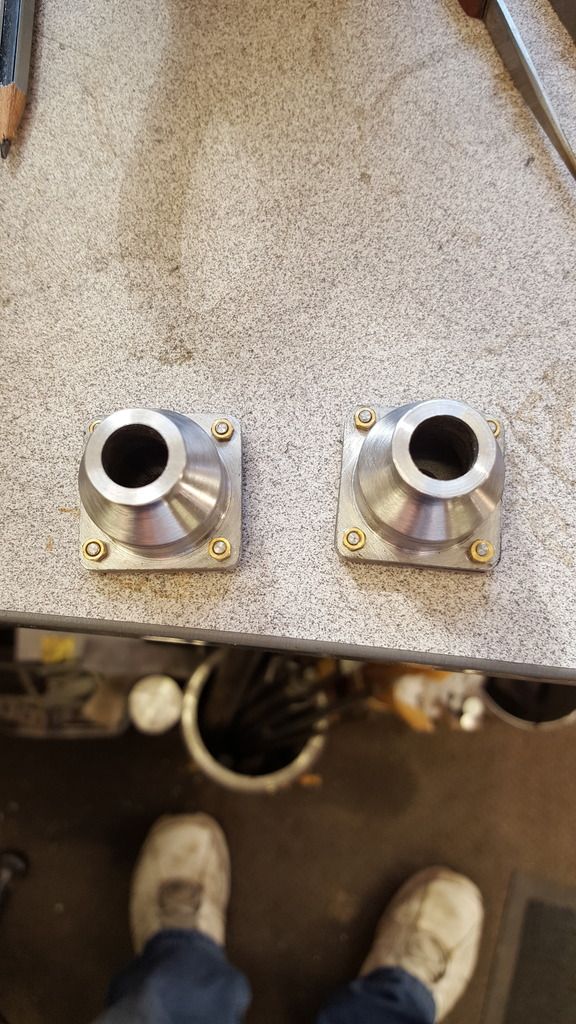
And here we have the first stock after being parted off, the second stock is nearly at this stage too and then I'll need to reverse them to bore out a recess that matches the exterior profile, I'll show that in the next update, oh and once all machining is done I'll polish out all of the machining marks.
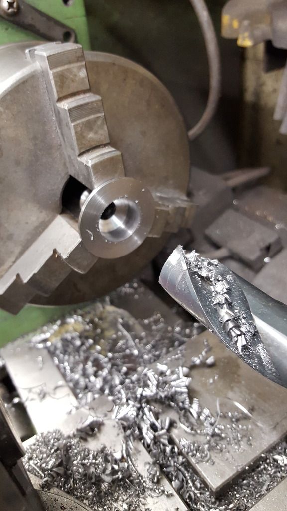
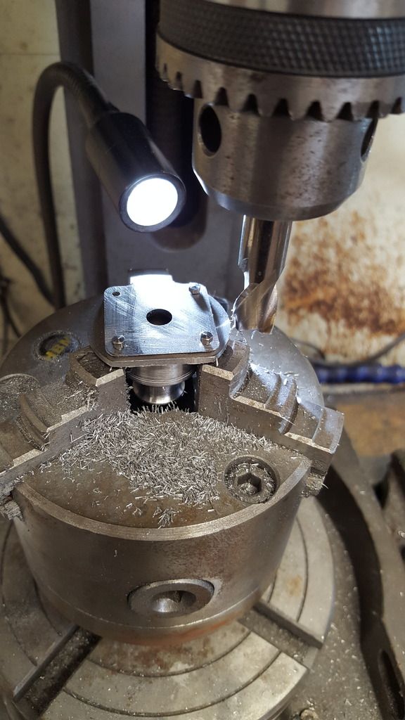
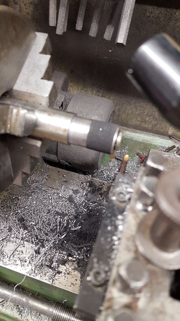
continuing with the buffers, once I had got the second buffer stock to the same stage as the first it was time to reverse them in the jaws to do the internal chamber. I used my recently purchased set of blacksmith drills to do this as the finished size was 13/16 which I had a drill to match. I started with a 9/16 as shown in the first picture, to begin with, I taped the drill to give me some visual control on depth but I later changed this to a pencil mark as the drill was greasy. Oh and I must get myself a set of soft jaws, I tried using some shim but it failed and thus I have some marks to take care off, they won't be seen once finished... such is life.
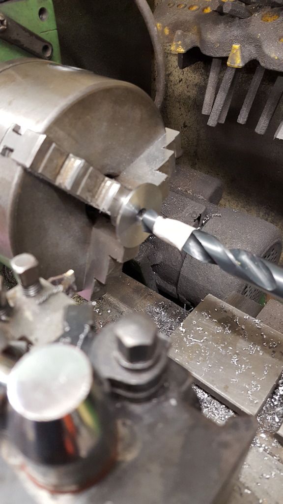
Now the angle is supposed to be 55 degrees, but since the drill tip is close at 59 that will do for me. The depth is determined by the outside profile having an equal thickness all round.
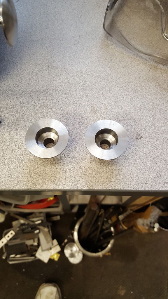
the two stocks ready for the next stage
I seem to have forgotten to take any pictures of the 4 holes being drilled on the rotary table which is very careless of me. basically, each stock was set in turn on the rotary table with some steel plates under the flange to give room for the drill to go through without hitting the jaws. A wobbler was then used to centre the table, once centred the head was moved out on the X axis by 0.625 to give the 1 1/4 diameter arc for the holes. It was then a simple job of clocking the table by 90 degrees for each hole which was first centre drilled and then finished with a No. 44 bit. Picture shows the first stock being checked for accuracy with one of the back plates temporary fitted which was laser cut for me by Malcolm (MEL). The back plates are 2mm thick and 1 5/32 square, I guess both Malcolm and myself got things right as they were a perfect match...
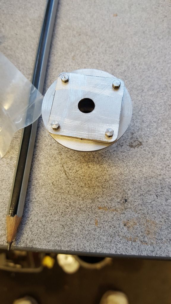
It was then time to machine the flat edges on the stock flange to match the back plates, picture shows this, the backplate was placed in position as a visual guide to make sure all was going to plan. I was using a 12 mm cutter and setting on X axis was 0.814. The first face was clocked 45 degrees from the first hole and then another 90 degrees for each of the others.
The two stocks with backplates fitted and the corners radius-ed to 1/8.
Here we have the components made so far, I still need to machine up the other stem, one of which can be seen here, this is made to fit into the stock and is a sliding fit. Overall length is 0.843, max width is 25/32 and the small width is 0.406 which is a sliding fit into the stock. Angle on the flange is to match the inner chamber.
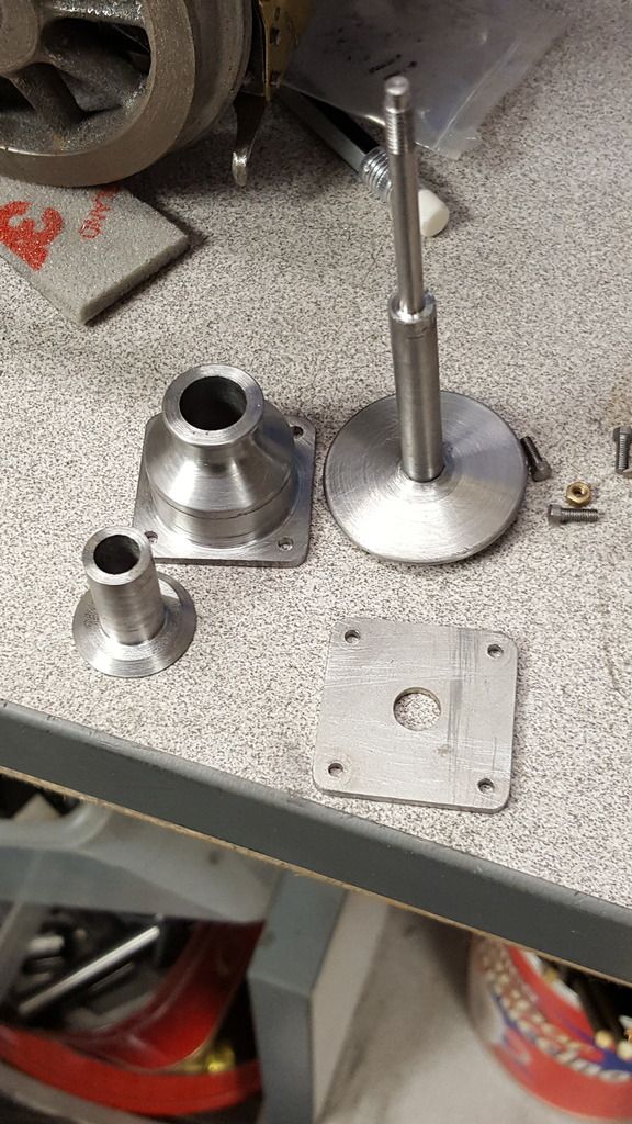
This picture to show the assembly so far, well except I forgot to include the backplate...lol...with the backplate fitted the buffer doesn't stick out so far from the inner stem and looks just right when compared to photo's of the prototype. A point to note here is that I have opened up the bolt holes a little, reason being was that I wanted a hole that was a very good fit to one of the transfer punches for when I transfer the holes to the beam, the larger holes can't be seen once the nuts are in place.
This part will see the completion of the buffers, I'm glad that they are now completed as they involve a fair bit of work, especially when comparing with the buffers for the tender, I wonder if any other buffer design has so many components?
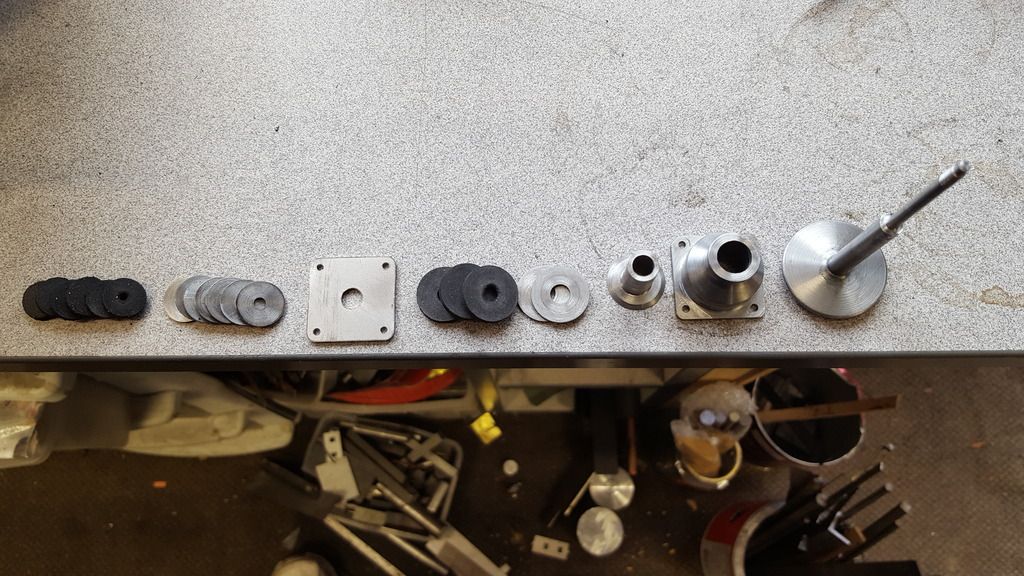
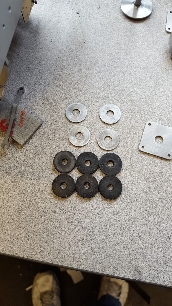
This picture is pretty simple, shows the disc's being set up with a stop in the tailstock and tooling set to cut at 1/16 width. All metal disc's are the same width but of two diameters, here we have the larger which fits into the buffer stock. The bar has already been drilled to fit over the buffer shank's wider section, there are 4 of these.
Once the disc's had been cut the same bar was then drilled tapped to be used for holding the rubber sectioned ready to be turned. The rubber is 3 mm Nitrile which was chosen as it's oil resistant, it also has what I thought t be a reasonable spring rate, I will admit to taking a guess here as I had no way of knowing how this would work once joined with the other discs, it just felt right and Don had mentioned to forget tap washers as they were too hard.
Here I have all 6 rubber discs to be machined together.
After turning..
Here we have all of the large discs, I made a mistake here, on checking the size for the smaller discs I noticed that the rubber discs are slightly smaller than the steel, as these are hidden in the stock and as there is a 1/16 space around them I saw no reason to turn then down further. I didn't take pictures for the smaller discs as they followed the same method of machining, there are twelve of these so i did them in 2 batches and there are 14 steel discs, let's just say that they kept me busy for a while.
I thought this picture might help explain what's involved in just one buffer, in fact I forgot to include the 2 slim 4 BA nuts and a small split pin to secure everything, the split pin will be done later, I have a few still to do, mostly for the tender. This is very prototypical and I just love that..

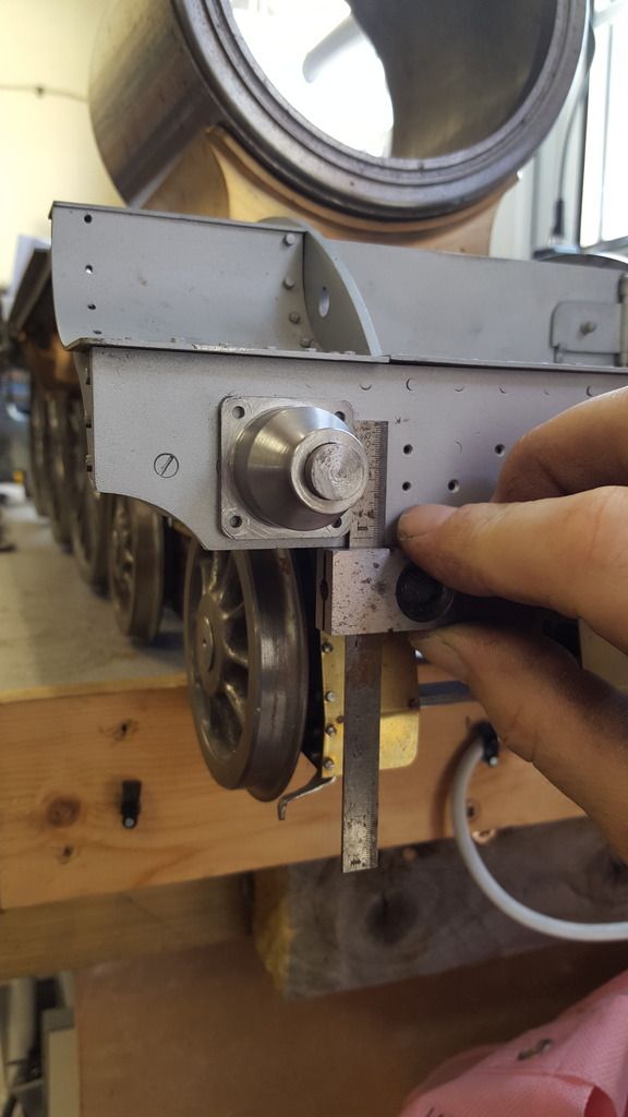
It was now time to drill the holes for the mounting studding, I first turned up a jig that was a sliding fit to the stock and a drift fit to the centre buffer hole in the front beam. with the jig tapped home I could simply slide each stock on and use a square for lining up and then transfer each hole. when doing this type of job I always do one hole at a time, drill, tap and fit a bolt to hold the stock on. check all is still square and then move onto the next hole.
I forgot to take a picture of the studding being fitted, with all holes drilled/tapped I cut up 8 x 1" lengths of 8 BA studding and using Loctite 638 bonded each one into the front beam, I did consider leaving these removable for painting but decided there would be no problem painting/lining with the studs there, I may even paint the beam with buffer stocks fitted.
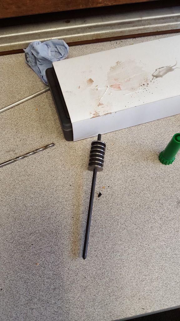
Once all was cured and primed I moved onto the assembly, the large discs where first inserted into the stocks, backing plate fitted and slid onto the studs and bolted up, alas I forgot to take a picture of this stage. With the buffer itself also in position this left the discs for the housings, now this is a real pain. At first, I tried to feed each disc on one at a time but this proved impossible as the assembly as a whole is compressed and although I could get most of the discs on I couldn't get the final few. I then remembered that Don stated that in full size these discs are all bonded to form two springs, he did give them a name but I can't remember it just now. So I took them all off and using a suitable transfer punch bonded each disc to the next using rubber superglue which worked very well as shown in the picture.
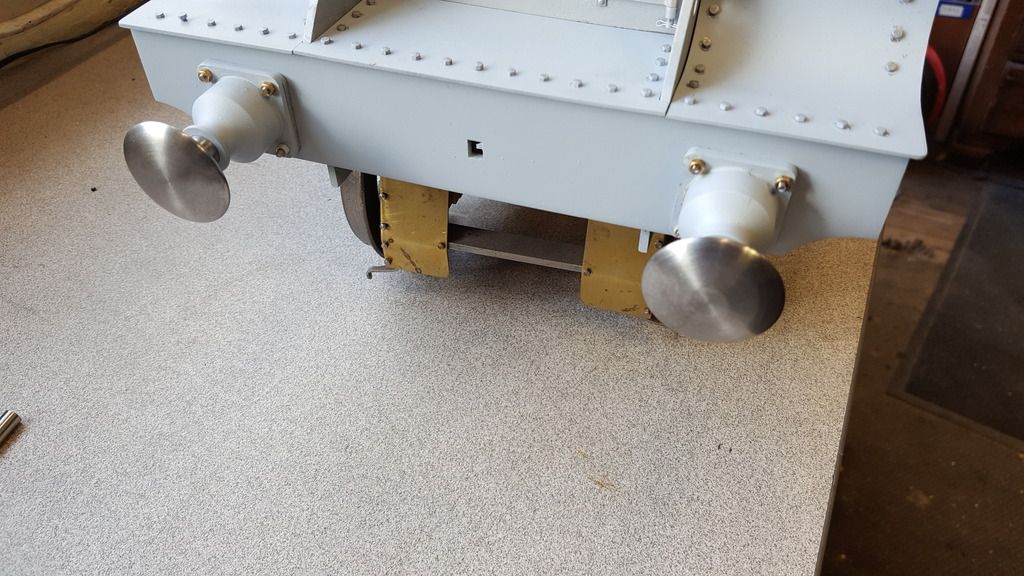
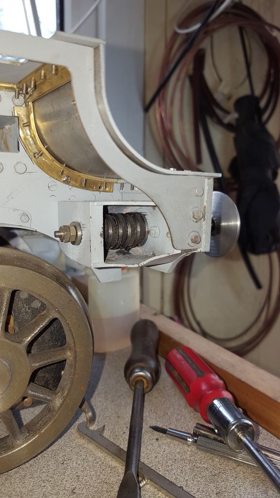
After still more effort I got the sprung unit into the housing, I have to say that it certainly looks the part and works as intended, the housing spring is softer than the stock spring so that you get two rates of action, both are very strong, I struggle to compress the stock spring which is how it should be. A last resort so to speak although as Don states buffers on the front of an engine aren't going to do a lot if hitting the end of a platform with a 500 ton train, I'll remember not to do that ...
The first buffer in place, also of note is that the front beam is now finished and that the 3 front running plates have had their overhang reduced to match the prototype, I've taken about 3 mm off.
NB: Now an error on my part to point out here as it's obvious in the next two pictures. When making the buffer stocks I blindly followed pictures of the loco as she is today and copied the BR fitment steps that you can see sitting on top of the buffer stocks in this picture. This was wrong and kindly pointed out to me, of course, once I got my brain in gear and actually looked at photos from before BR days I could see this for myself. So some time wasted but easily rectified as will be seen soon. Also of note is that today, Flying Scotsman has too different pattern buffer stocks fitted, this is very obvious if you look closely.
I've tried to take this picture at the same angle I have of the prototype that best shows the buffers.
Ok, so thanks to the timely intervention I have removed the buffer steps, not sure why I fitted them as they are clearly absent from all of my reference photos for my chosen era. My memory can be a pain at times, this being such a time as I do now recall discussing these steps before, anyway, all sorted now and thank's Eddie for keeping me on track.
For now here's a picture to keep things on track of the buffer stocks minus their steps...