

NB: When I first wrote this I was looking for some information in regards to the front running board hatch as it isn't on Don's drawing. I will include the various post's to show what I discovered and how I went about researching the info required.
"This isn't so much an update but a plea for information, does anyone have a works drawing that shows a plan view of the smokebox running board? I have been working on this area and after making said board to Don's drawing have noticed in my reference photo's that there's a hatch in the board that's offset to the left hand side and I want to include this on my model".
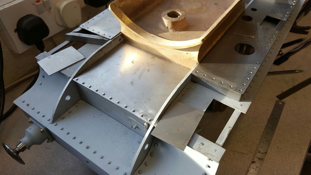
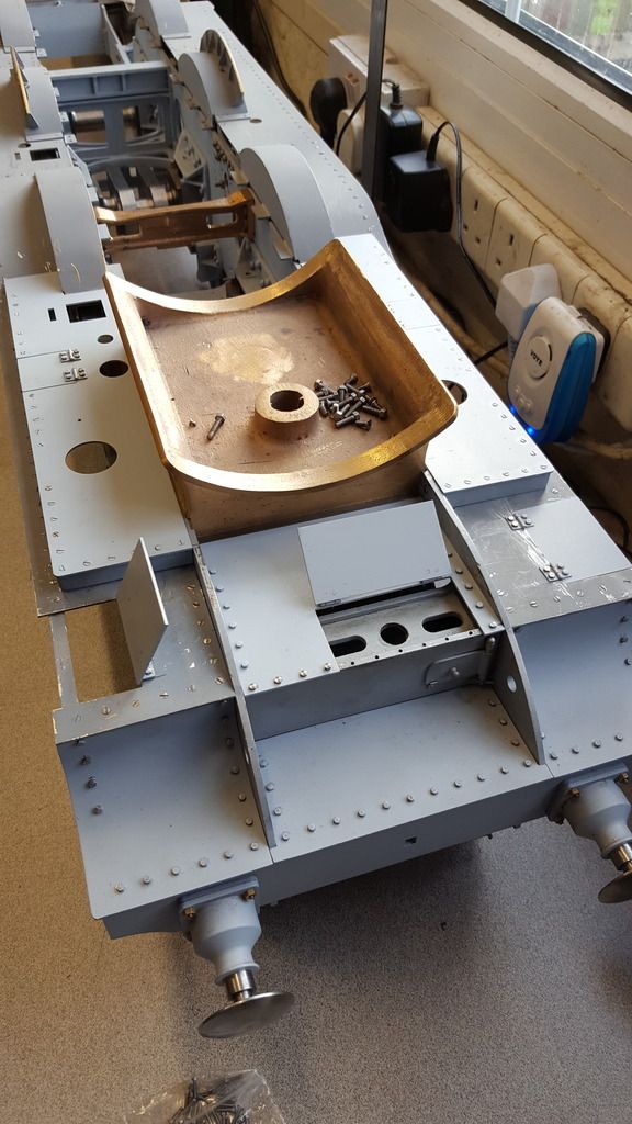
Here's a picture of the board on my model that I'm referring too, having discovered said hatch I now need to modify this board.
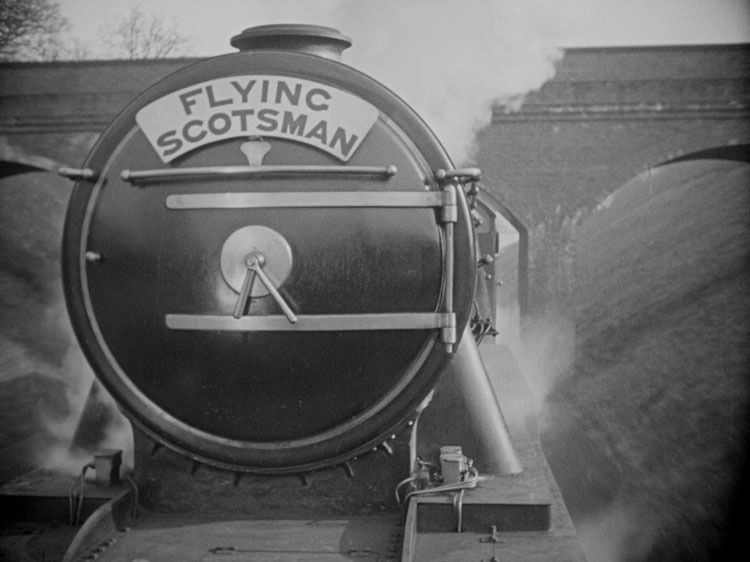
Here's 4472 in 1929, an image taken from the film of the same year'Flying Scotsman' which clearly shows the hatch and also of note the row of bolt fixings down either side of the frames, both of which are not shown on Don's drawing.
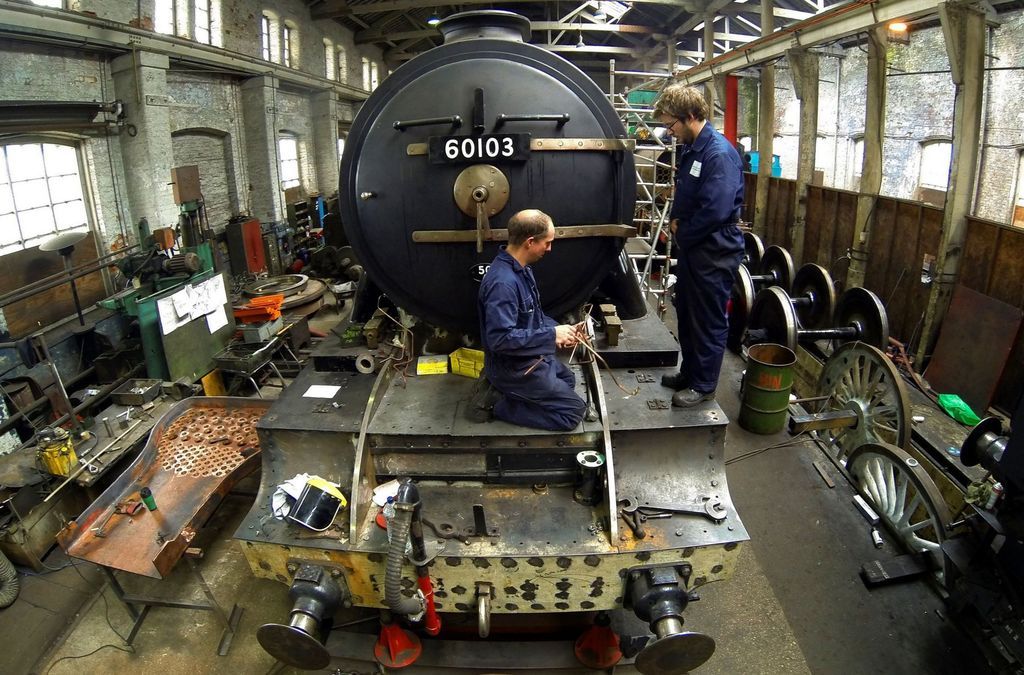
Flying Scotsman today....
Now I could possibly work out the info that I need from the reference photo's I have but if by chance anyone has a works drawing or photo looking directly down on this area it would help me greatly.
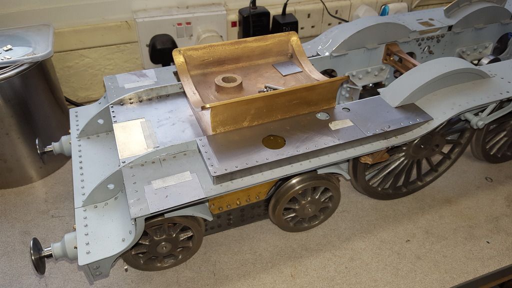
Well, no drawing came forth so I have scaled the door from the photo's that I have to hand, working out the width was easy enough as I have the photo that looks straight towards the front so I can scale the width pretty accurately . The depth is a little more problematic as the only photo's that I have are at angles from the front, however the picture that I posted of the still from the 1929 film came to my rescue as I can see both the smokebox running board and the side running board doors and thus could take a line across from the back of the smokebox door and see where it met the side running board door. This is close to half way of said door which happens to be roughly where the back of the 2:1 gear stay ends so I took this as a good omen and modified the panel accordingly.
Picture shows progress so far, I now need to get the other upper running board to the same state as the one that's in position and then that lovely tedious job of drilling/csk and tapping yet more 10 BA holes. The plan is to do most of them using short csk 10BA screws but also a small number that go straight through the 10 x 5 mm steel uprights and tapped into the running board below to hold in position. oh and I still need to make two more hinges.... BTW the new door is made from brass as it was the only material that I had to match the 1.2 mm steel panel.
I have covered how I make hinges before when doing the tender lockers so won't go through the basics but these ones I tackled a little differently. The length of tube soldered to a similar length of flat stock and then cut up into blocks close the required hinge width was done the same as before. This time though, I wanted to ensure that all were the same with the same spacing for the mounting holes , same goes for the holes in the running board, they needed to be identical. Simple enough if using a jig and so choosing a length of stock of the desired width I first machined across said width with a small ball nose cutter creating a recess for the tube section of the hinges. I then drilled 4 holes equally from this centre line, two either side for the mounting hole positions. I didn't take a picture of this but it's clear to see in the following descriptions, note that I used a relatively thick bar stock to ensure that the holes when transferred, didn't move while being drilled.
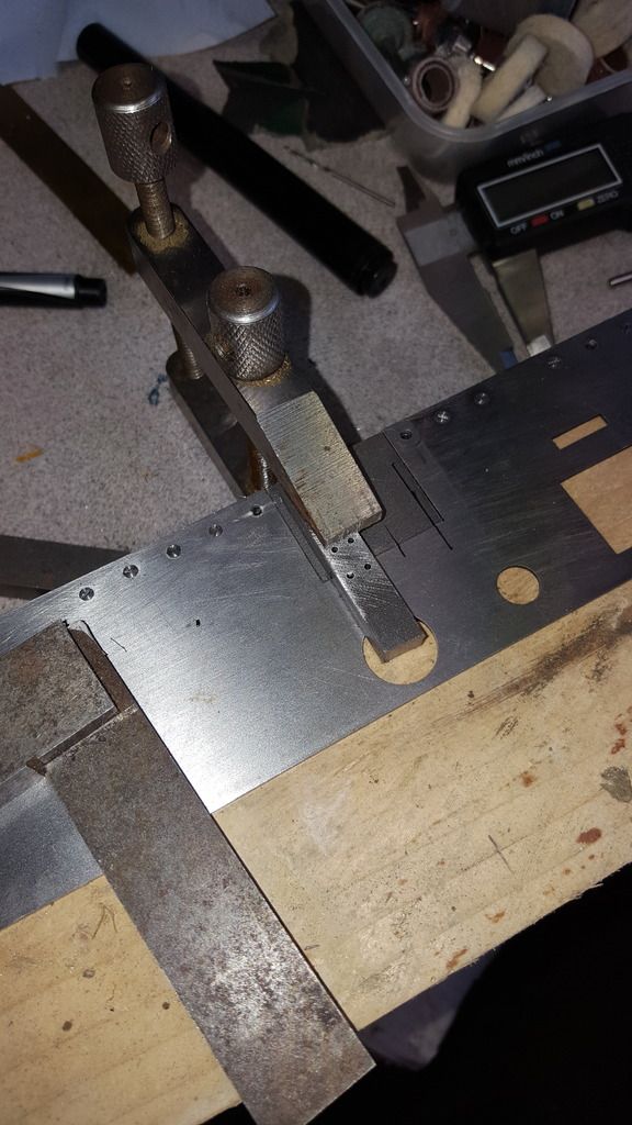
Ok, so the first picture shows the jig being used for the upper running board flap, the running board is held flat on some wood with the flap positioned and held by a clamp which also holds the jig. The position for each hinge was plotted from the outer edge of the opening, I just chose what looked right for hinge size to flap size and pictures to hand. There is a centre line scribed on each side of the jig to line up with the joint to keep the hinge central. Note that the holes look a bit off square, they are this side but not other, result of drilling so to quickly deep with a 1.4 mm drill (10 BA tapping size) using a blunt drill bit. Makes no difference for this job, I received my order for new bit's today after doing the work...lol Before drilling, a square was used to ensure that the jig was aligned correctly...
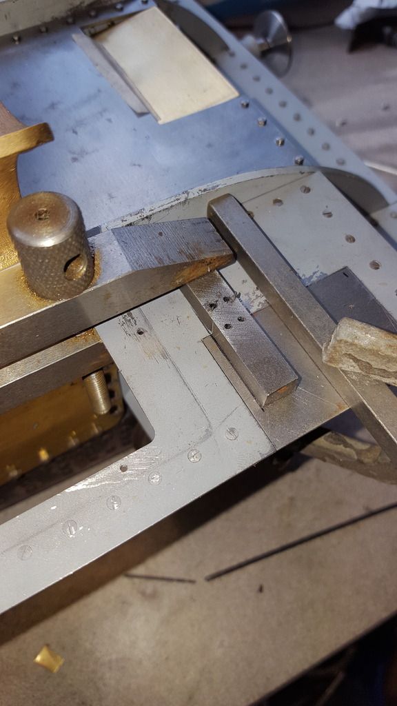
I then needed to repeat this process for the other hinges, 10 in all. For the centre board I just removed it and used the same method as for the upper boards but for the main boards I decided to do the drilling in situ, purely as I didn't want to spend hours taking everything apart when I could see a way of doing this with the boards in place. Picture shows the jig once again being held in position, this time you can see the scribed line that ensures the hinge is central. This took a bit of work, well the whole job took some time, but these took a little longer having to reposition clamps for each hinge, still it worked fine and I was happy with the result. The square bar clamped in the middle was to hold the flap in place and level for drilling through the jig.
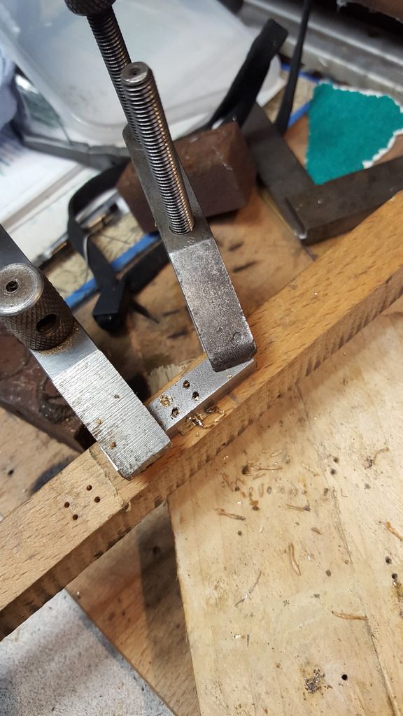
Next job was to drill the corresponding holes in each of the hinges, these need to be 1.8 mm for clearance but for now, I drilled them at 1.4 through the jig as I still need it at 1.4 mm. This time the jig was turned over and used to hold each hinge to a piece of wood with the aid of two clamps. You can see a hinge being held thus in the next picture, note that at this stage the hinge is wider than the jig, this will be dealt with next.
With the holes drilled it was time to get all of the hinges to the same width, going back to the jig the holes were first tapped 10 BA and then each hinge was held tightly in place via csk screws, it was then a simple exercise of filing down each edge using the jig as a button, if the hinges had been made of steel I would have hardened the jig first but saw no need when made of brass. Last job to do here was to clean up with a little filing and the opening of the holes up to the required 1.8 mm.
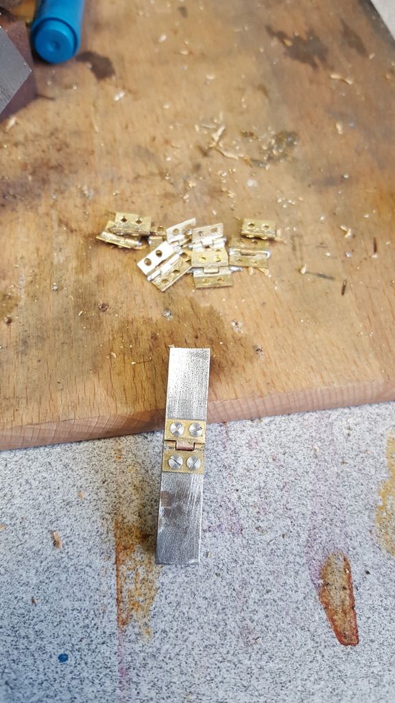
Last picture for today showing the covers all bolted back to their respective running boards, this was a fairly long-winded affair but well worth the effort IMHO, I have left two covers open to show they work.
So what's next? well, I think while I'm in this area I may as well do the lamp iron,s I have already started to cut metal. I had thought that I wouldn't need to do the grab rails, thinking that they may be a later BR addition, they certainly aren't on Don's drawing and nor have I seen them on any of my reference photos taken during the 20/30's but a new photo that's turned up(new to me) that shows 4472 as in the late 30's, certainly after 38, shows very clearly that the grab rails were present for my chosen era....One thing that I do know, is that I have a million and one jobs left to do just making good on what's been built so far, certainly a hell of a lot of work before she's ready for paint..., oh well,best get on!
NB: Hope that made sense, I will try to edit less in future to save time as long as the written text makes sense.