
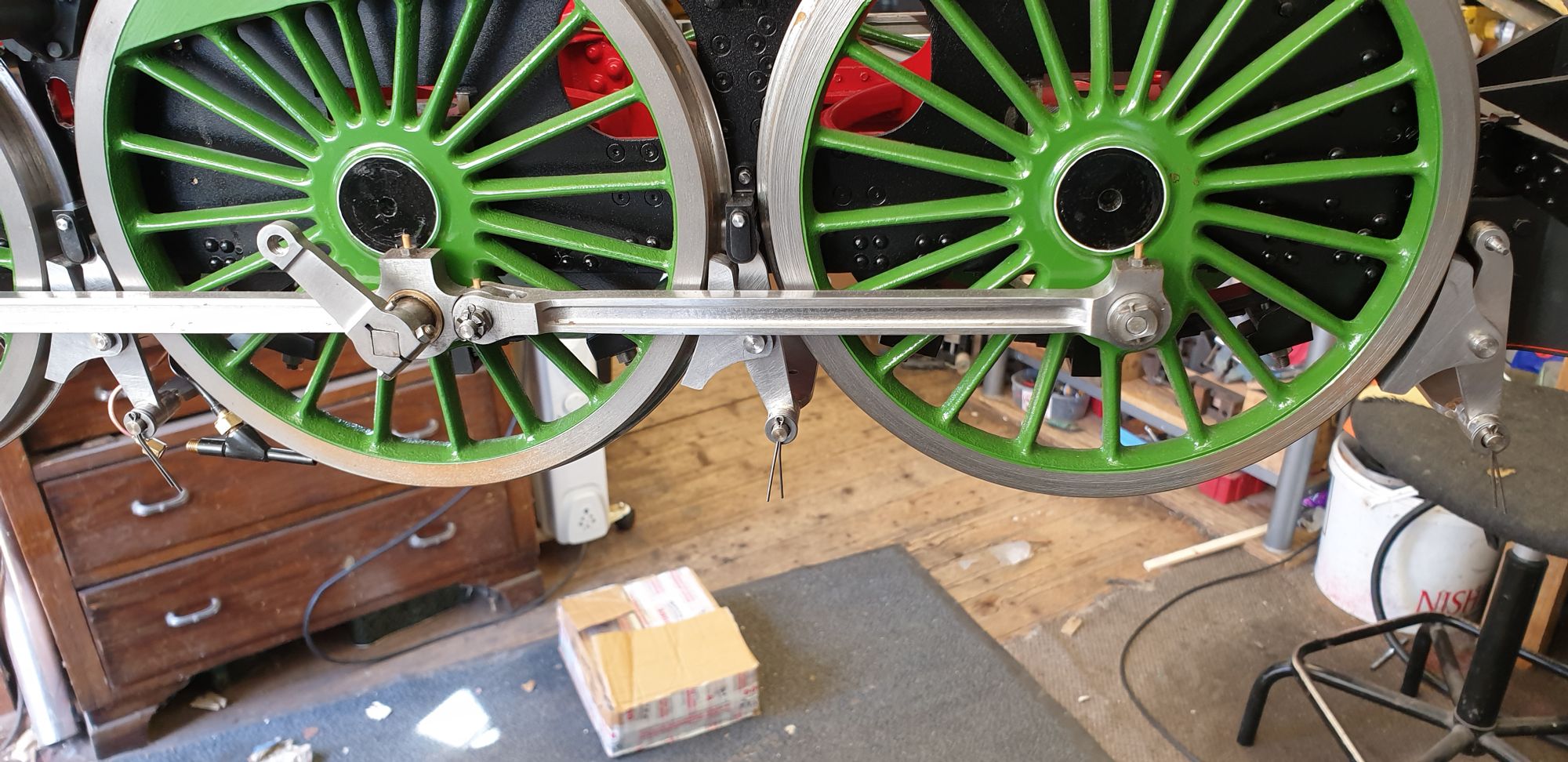
I decided that it would be wise to test fit the hangers along with their cross beams before moving on to the pull rods.
You can see the brakes hanging in the 'off' position, No drama here but as expected I will need to re-shape the steam sander pipework to allow enough clearance for the cross beam between leading and crank wheels. I'll tackle this once the brake components have been made and tested. Once that is done I'll return to the steam sander pipework and adjust as required.
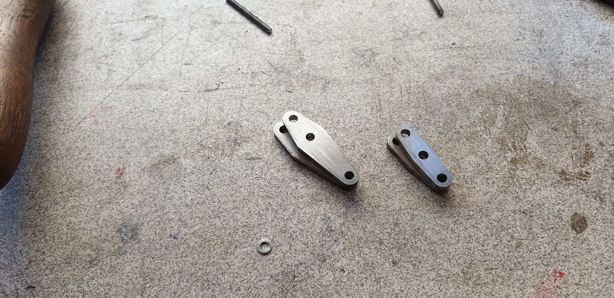
Links and compensator's
Here we see the two types of compensator's,, the smaller 1:1 compensators are for the middle beam with the larger for the front brake beam. The holes are all No.30 drill which the pins made earlier will fit into. These parts are the final laser cut items from Malcolm's brake set, alas there are no parts for the 8 x links themselves, these will be done the traditional way. I currently only have one laser cut item left, that's the backhead cladding sheet, in fact only have one large casting left too, that being the dome. Some might think this means we are nearly finished... if only...I still have a long way to go yet, I have all of the backhead fittings to do which will involve some castings, yes I have a very long way still to go.
Next up was the 8 links, alas these are not in Malcolm's range of parts so over to the saw and files.
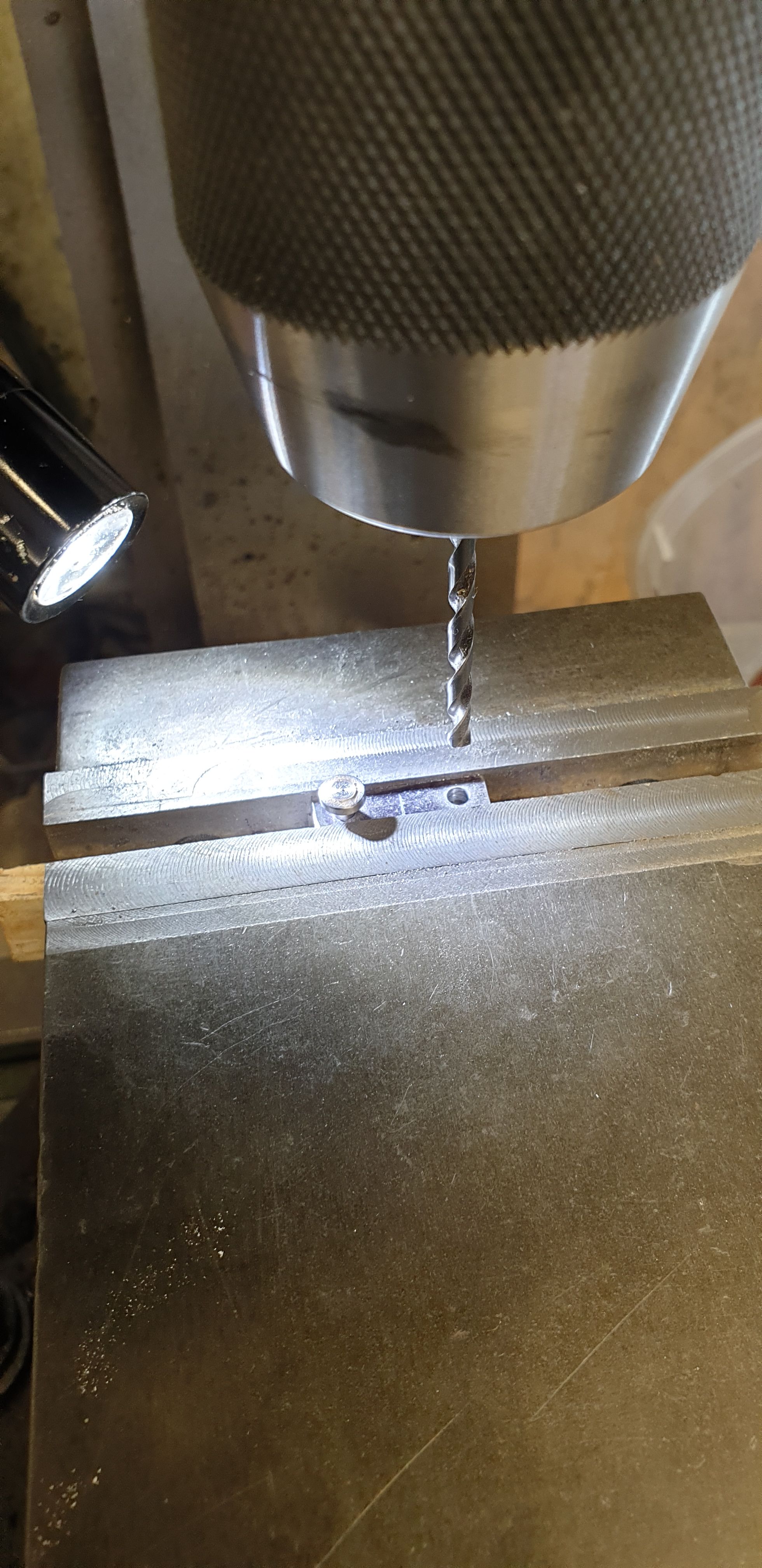
First I cut 8 pieces of 1/4 x 1/16 steel flat bar into slightly over length sections, approx 1 inch long. They were fully cleaned and de-burred and then bonded together into two groups of four using Loctite 638. I gave them approx 30 mins to cure and then marked out the top piece with a marker pen and plotted the centre as can be seen below.
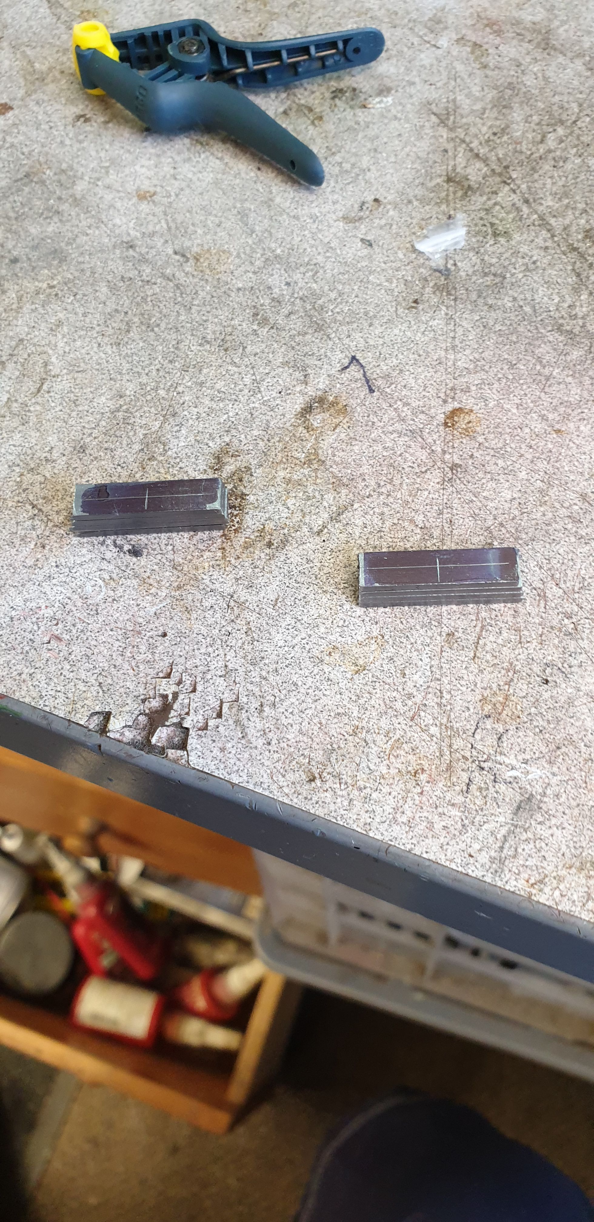
The number 30 holes are 5/8 apart, I simply held each batch of 4 in the machine vice, zero'd on centre and then moved X 5/16 for the first hole. Once that was drilled I inserted one of the pins to ensure nothing moved, advanced X 0.625 and drilled the second hole, giving me the 5/8 distance between centres.
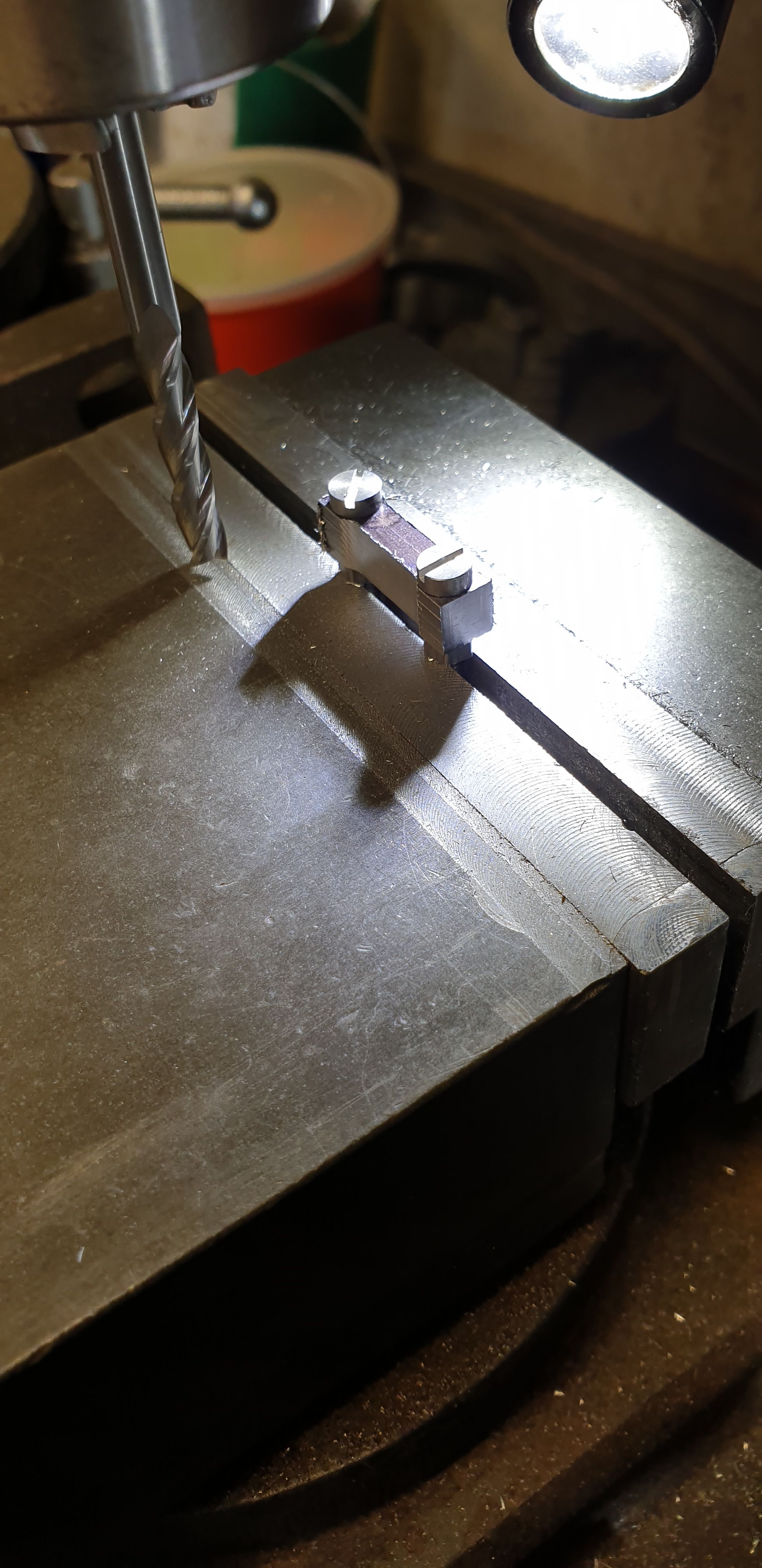
I then cleaned up all 8 parts, removing any loctite residue and burr from drilling. The two groups of four where then bolted back together using 5BA screws. I used long enough screws for a nut to tighten them up with and also a long enough section for the parts to be both held in the machine vice for the next machining operation and also to hold them in the rotary table after.
The next picture shows one of the group of parts held in the machine vice, first the ends were machined square, after that I machined the scallop on either side, this is 0.032 in from either edge.
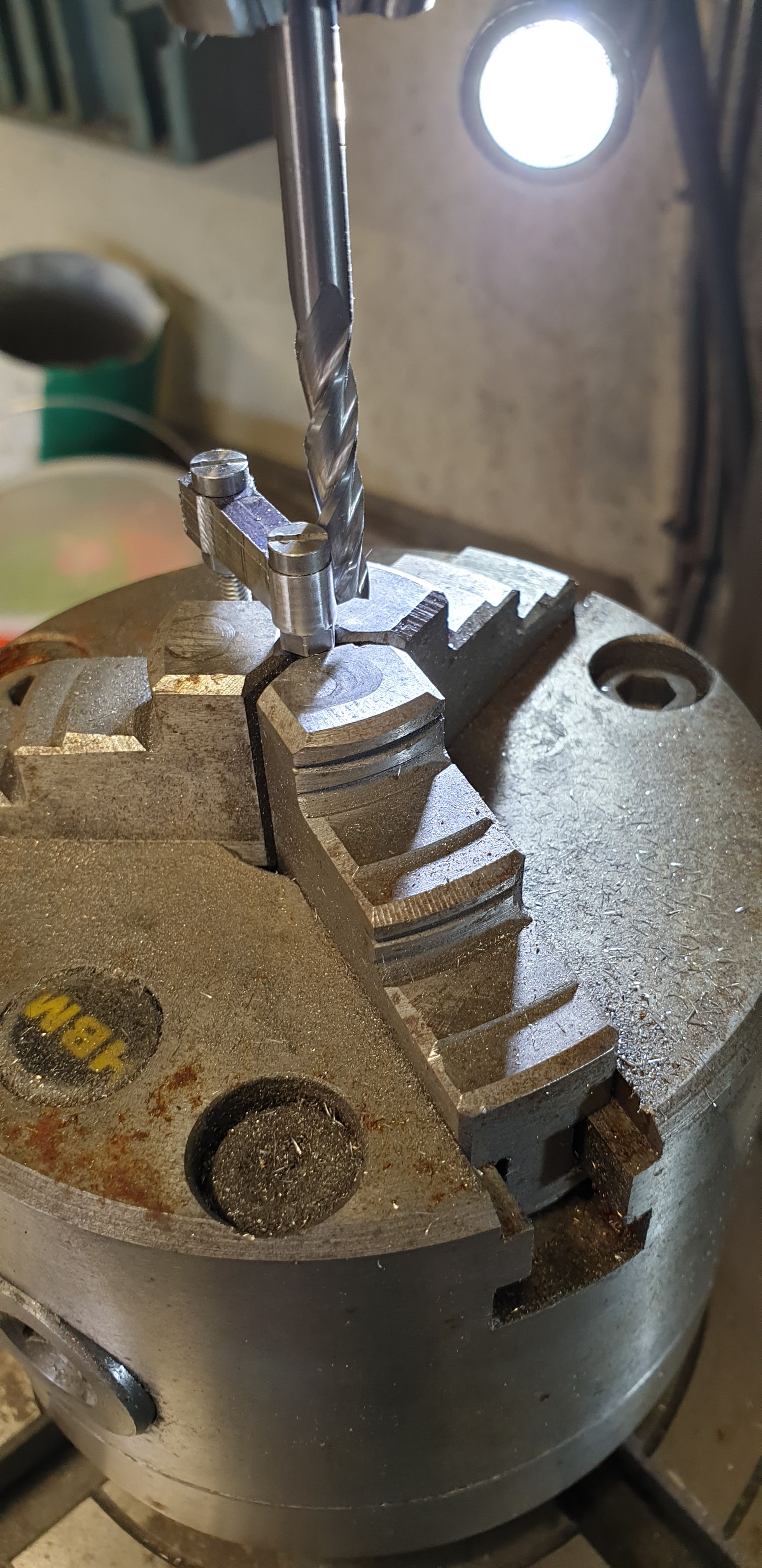
It was then over to the rotary table, I didn't trouble myself with making any 'button's, the screw heads are slightly smaller than the required size so I judged it by those and worked by eye, of course, all 4 ends were machined to the same diameter.
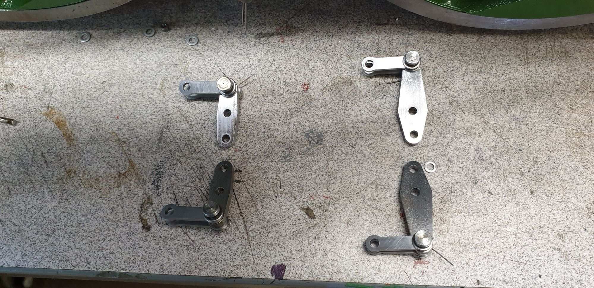
After a quick filing and polish the we end up with these parts..
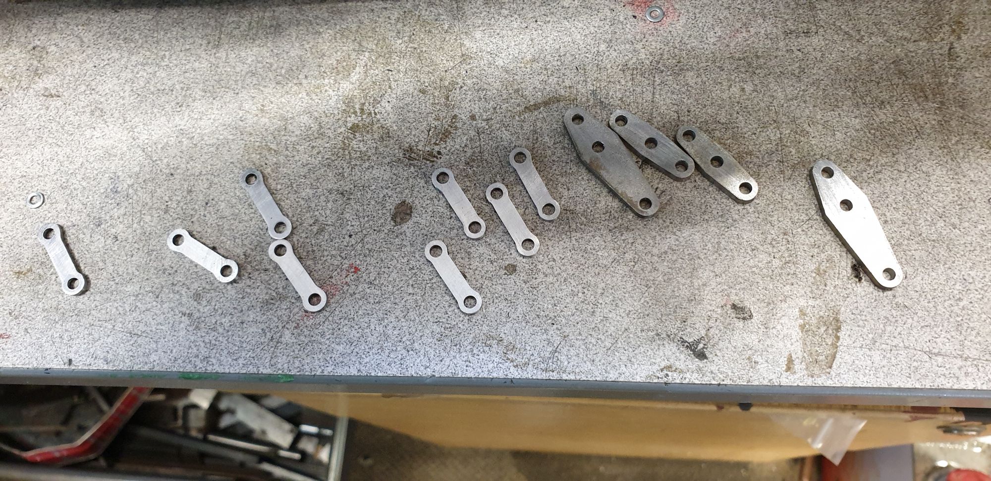
Lastly for the compensators and links here they are assembled. I have laid them out as if the loco is facing to the right.

For the next entry I hope to cover the pull rods and adjusters