Don suggested fabricating the water filler tube using copper tube, I had none of the correct size, I did however have some brass billet, a bit wasteful perhaps but at least I could get on with it.
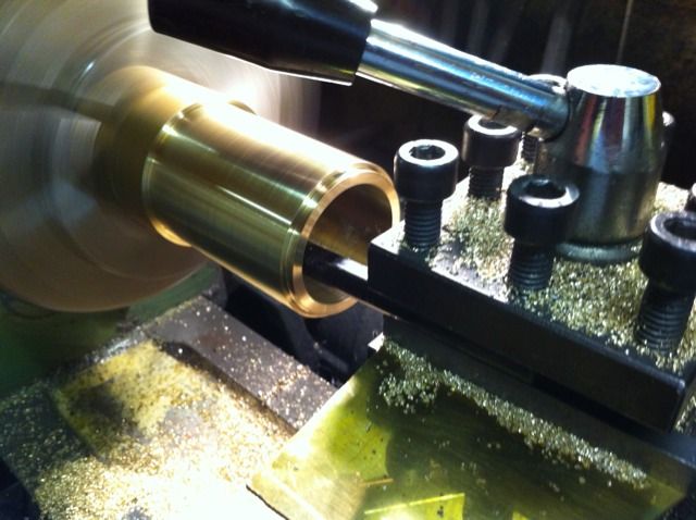
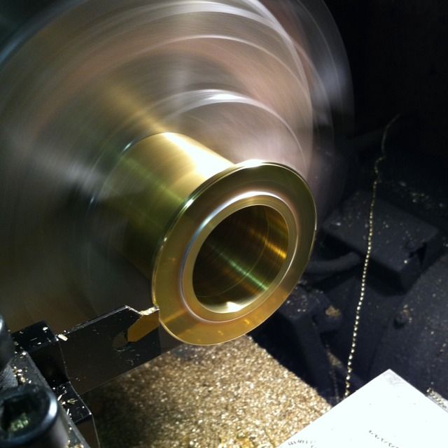
With the billet held in the 3 jaw, i faced off and then turned down to size. The billet wasn't large enough to include the mounting flange so this was added after.
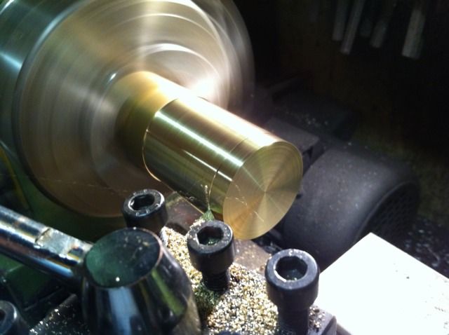
To help line up I machined a spigot on one end to make life easier when mounting to the top plate and then spot drilled, ready for drilling and boring the filler neck to size.
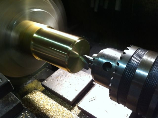
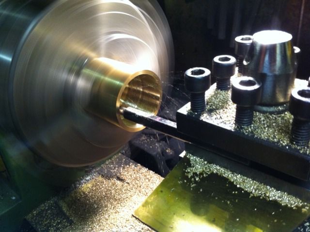
Bored out, this was undersized as I wanted the step (spigot) for easy locating. As drawn the filler hole was the same size as the hole in the tank top so I machined the bore slightly smaller to give me enough metal to allow for the spigot.
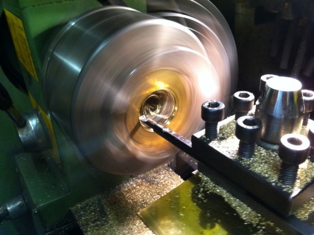
The job was then parted , reversed in jaws so the top can be machined. I also opened out the top of the bore down to about to about 3/4 depth remembering to leave enough material at the bottom for the spigot.
Next job was the bottom ring, this was first cut roughly to size, fixed in 3 jaw with packing, centre drilled and then bored out to fit the filler tube.
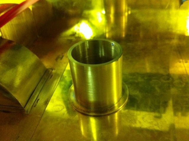
The ring was then soft soldered to the filler neck.
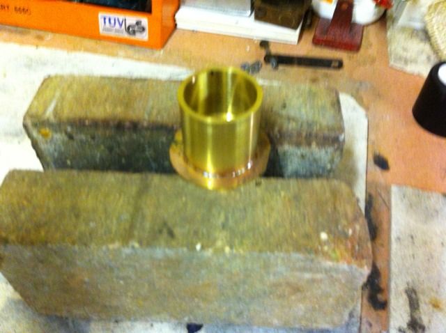
With the ring now securely fitted to the tube it was once more reversed in the 3 jaw and the outside radius was machined to size.
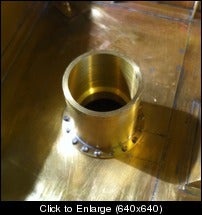
The filler neck was then tested for fit,

I decided to attach the tank filler neck with hex heads rather than sweating it on as Don suggests, gave me good reason to play with the rotary table, here the holes have been drilled. This is not necessarily prototypical as some pictures that I've seen have this ring whereas others do not. Well mine has and it's held in with bolts...

The holes were then transferred to the tank top and drilled/tapped 8BA
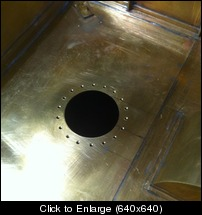
We then had the filler neck firmly attached to the tender top plate.