These are large pieces of brass and care needs to be taken when forming them as any buckle or deformation will show up very easily on a flat panel of this size. The time consuming part of sawing/filing, I don't need to worry about as they are already laser cut, but they still need to be formed and being nearly two feet long and with no rollers in my arsenal, this required a little thought/planning.
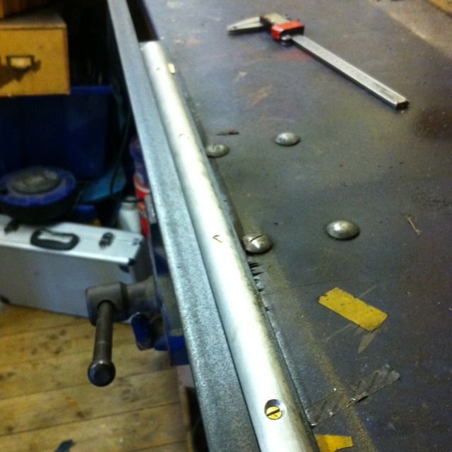
The picture shows the former/jig that I used, I might add that this length of alloy was first cut down the middle using my small band saw, good job I had a very good blade made for it some time ago. The original plan was to clamp the top edge of the tender side between two right angle pieces of steel with one if these having a piece of alloy of the correct diameter which had been cut lengthwise bolted to it. The two right angles where clamped together with the one without the alloy bar being positioned higher than the other. The reason for this was to reduce the possibility of the brass sheet slipping out when forced around the former. Now this worked perfectly for lengths of brass 1 mm thick and 300 mm long which I used for testing when working out how much material was needed to be held between the right angle to give me the correct shape, remembering that these tenders have a radius close to the top edge which then flattens out for a short distance.
Unfortunately when it came to forming the sides themselves it wouldn't work, well not so much it wouldn't work more that I didn't have enough strength to form the brass which is double the test piece length and thicker too. I didn't want to go anywhere near these panels with 'heat', so annealing was ruled out early on.
So plan 2, leaving the former in the vice I laid the tender side on it, if you look at the picture and imagine the brass lying on top with the section to be curved over the alloy bar. I then calculated exactly where the brass needed to be and screwed a length of timber along the bottom edge into the top if the bench. Next was to clamp another piece of right angle along the top of the brass, trapping it at the correct position over the alloy former , this allowed me to then beat the brass around the former using panel beating hammers. Hope I explained that well enough, once I had decided to do it this way each panel only took a few minutes.
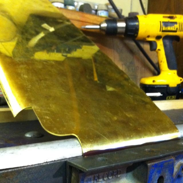
Once the tops of the large side panels had been rolled, it was an easy task to do the front curves using the former jig as originally intended
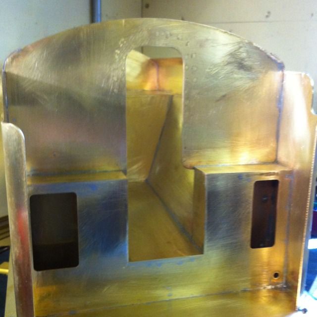
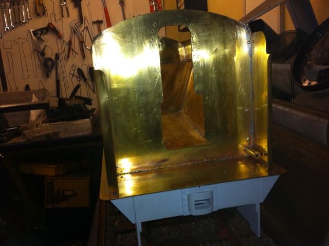
With the sides rolled I could now make a start on assembling the panels. The rear was done first, followed by the front after I had first turned up a short length of brass which was drilled, tapped, stepped and brazed into a matching hole for the step in the front panel, which can just be seen bottom right. This is for the working water gauge once it's fabricated, the drawings weren't very clear here as they only show the hole for the gauge on the locker panel, which yes has to be done too( I did both at the same time while clamped together) but since it's a locker and not part of the water tank I can only assume that there is some sort of connection pipe running through the locker from tank to the gauge, anyway I've tackled it with my brass tube which the gauge will screw into later. Finally the side panels were soldered on and I finally had something that looked like a streamlined non corridor tender...
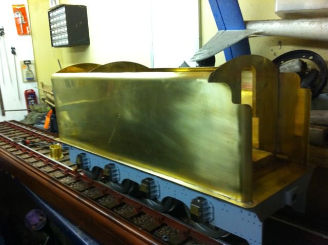
A view of the front which shows the brass tube much better
And now we have the locker panel and its shelf soldered in place. The hole, bottom right, is where the water gauge fits.