

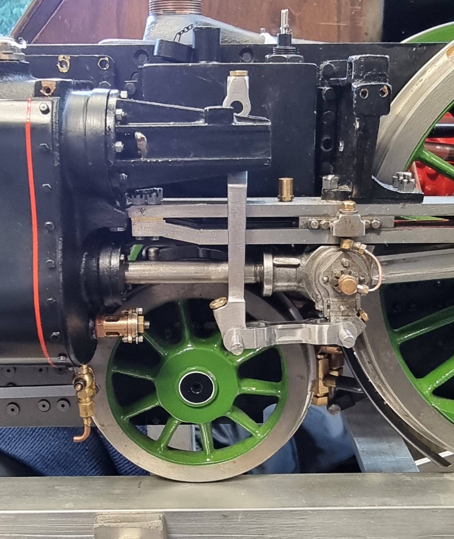
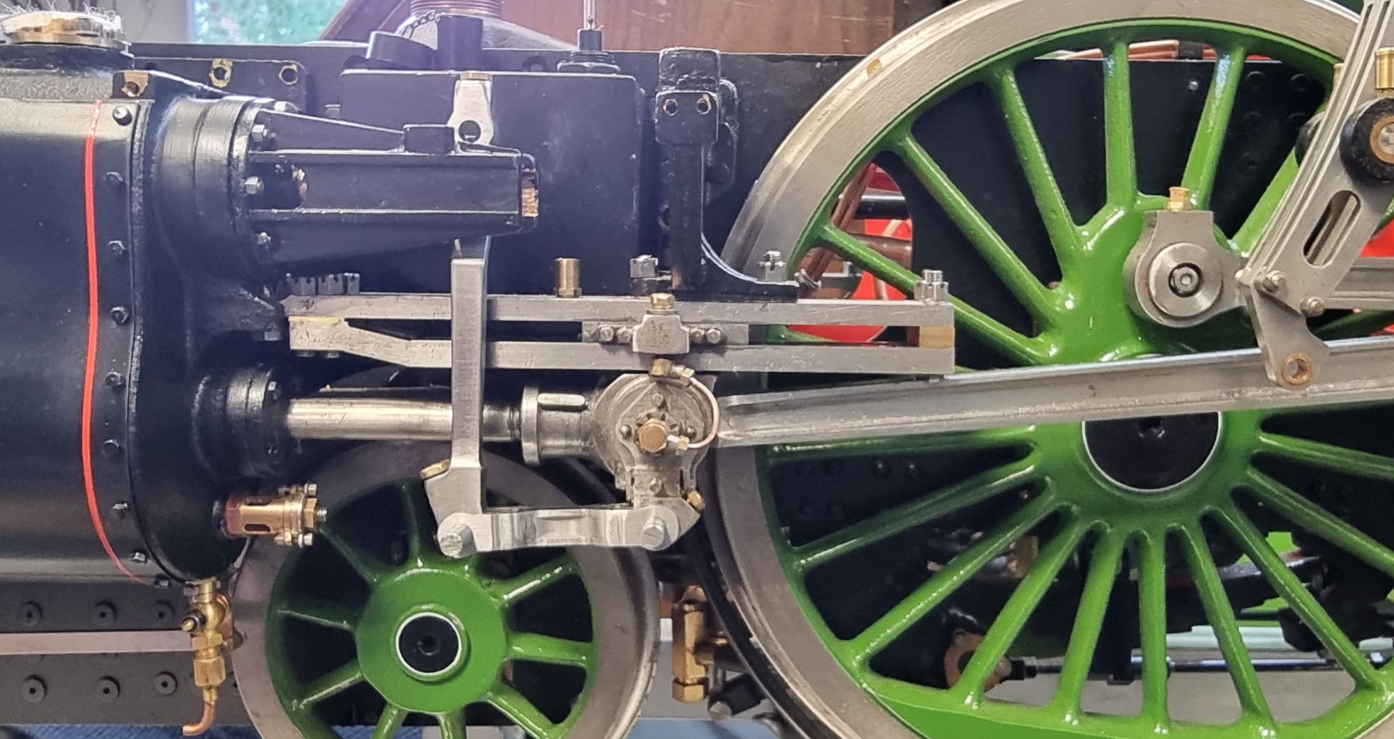
Once these are made and fitted I'll for the first time have the 2:1 conjugated valve gear working, exciting times ahead.
The union links are pretty straightforward machining but I'll cover them anyway to keep the build complete. I'll begin with the drawing and point out that of all the valve gear dimensions on this model, when it comes to the union links I won't be following Don's critical dimension, that is the length between center's. Some years ago the late Don Ashton did spend some time going through Don young's valve gear with me, well I say 'with me', those who knew Don will know that he lets you do the working out and he confirms if it's correct or not. I have forgotten much of what I learnt from Don but do recall that overall the valve gear was good as drawn but could be made better. Another fellow model engineer who's no stranger to most , John Baguley, has also taken a look at the valve gear for me and made one suggestion which was the length of the union link. I quote:
It's pretty good but the
length of the union links needs altering slightly to make it very good.
Don gives the length as 1.375" but it needs to be reduced to 1.344".
That slight change makes all the difference and the cut offs are equal
to within 2% over the whole range in forward and reverse.
end quote:
Now I'm still relatively new to the world of steam but I trust John's opinion as I do the late Mr Ashton and thus 4472 will employ the slightly shortened union links. Plus today we have the advantage of the simulators which John ran the dimensions through, something Don wouldn't have had back in the early 80's.
Here's the drawing along with my notes for machining.
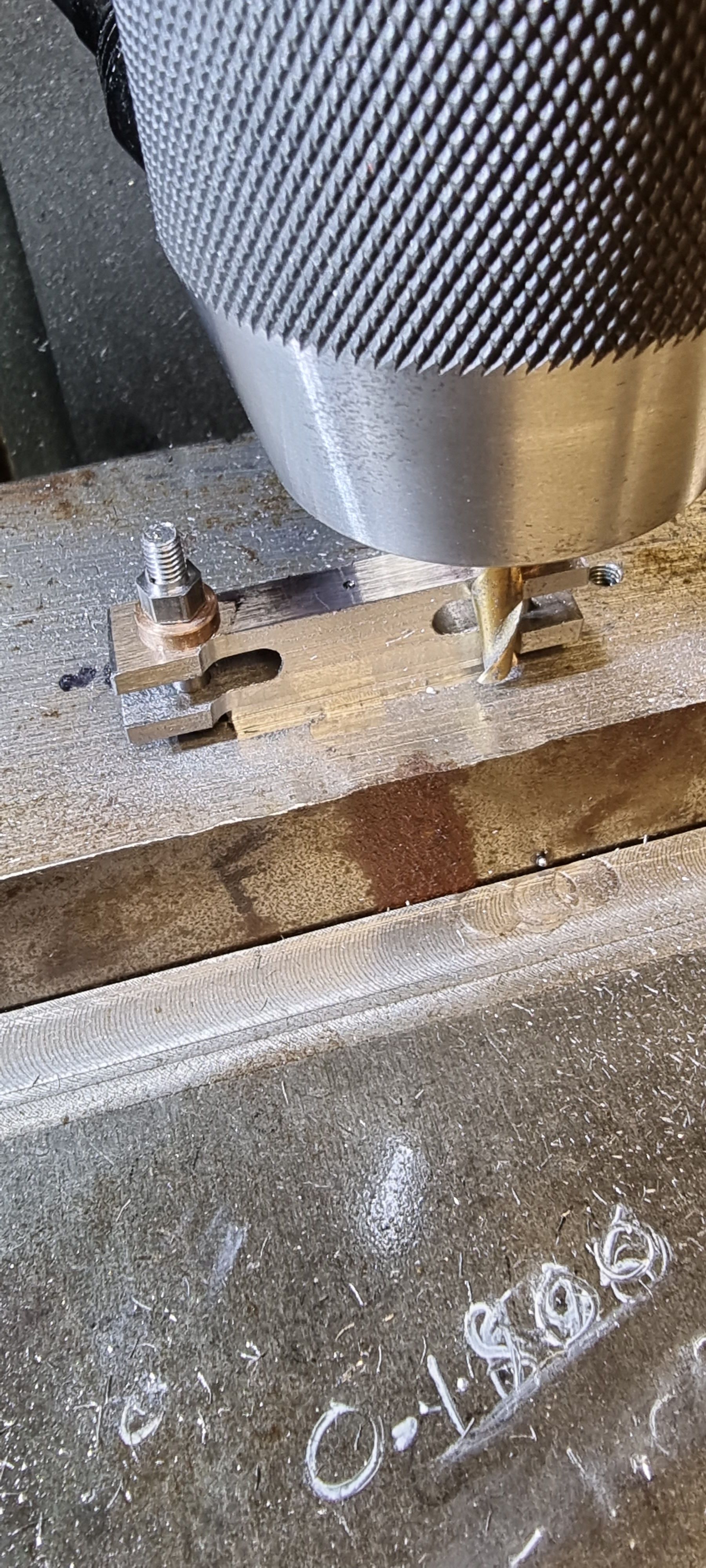
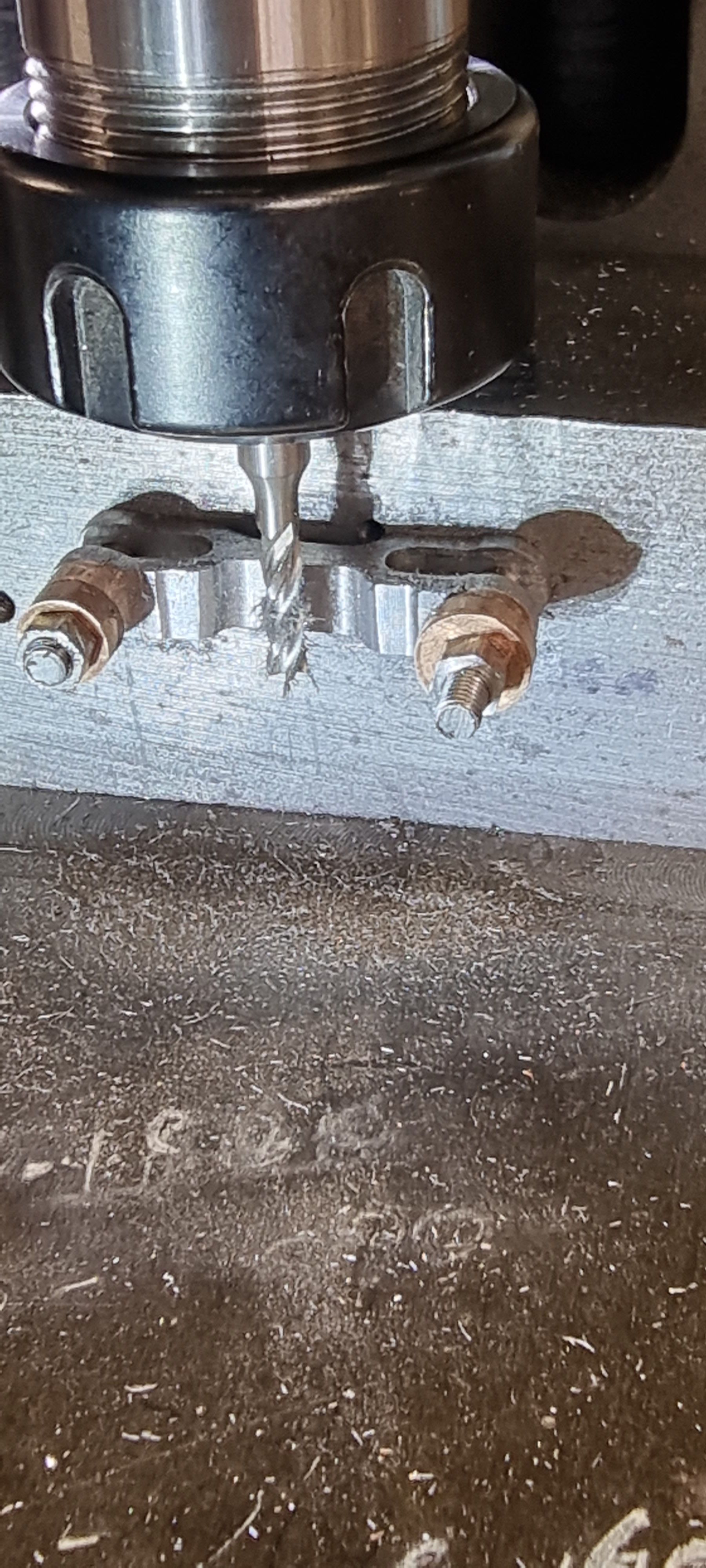
The two 5/32 holes were drilled/reamed first at the fore mentioned 1.344 distance between center's. As with all of the smaller motion parts these are made from gauge plate, all others being HRPO steel
Each was then clocked 90 degrees to begin machining the slots, chain drilled first and completed with a 3/16 slot drill.
Here the slots are completed and tested for fit on the combination lever. I have included one of the combination levers in the picture to show that they have now been fitted to the valve crosshead.
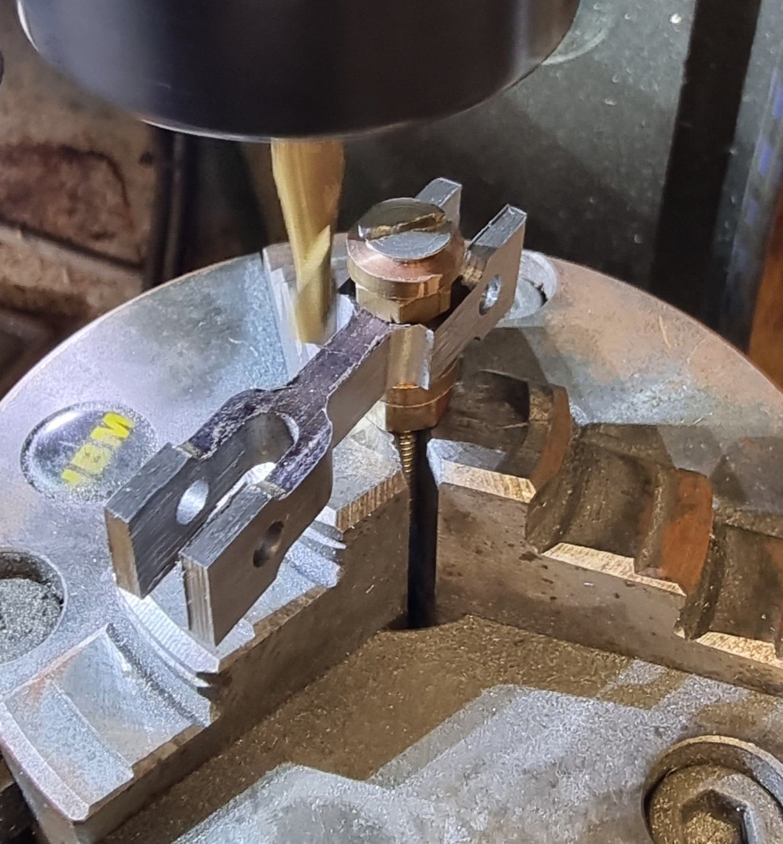
It is now time to begin profiling the links, I have done mine in a different order to what Don shows for no other reason than it suits my setup better. After machining up a couple of 5/16 buttons I held each link on the jig with a small strip of steel trapped under to protect the cutter from needless machining of the jig. Note that I am only using bronze here and thus not hardened as per usual button making. They are being used as a marker for machining rather than something to file against. Here I have reduced the middle section down to 1/4, in fact I have left it a few thou over for now. Next I clocked the jig 90 degrees (upright) and machined the middle down to the indicated 5/32 width, alas i forgot to take a picture of this stage.
with the middle at its required 5/32 I then moved to the rotary table to curve this section into the outer edges. the picture showing that one end has been completed with work starting on the next.
Staying with the rotary table I then machined the 5/16 ends.
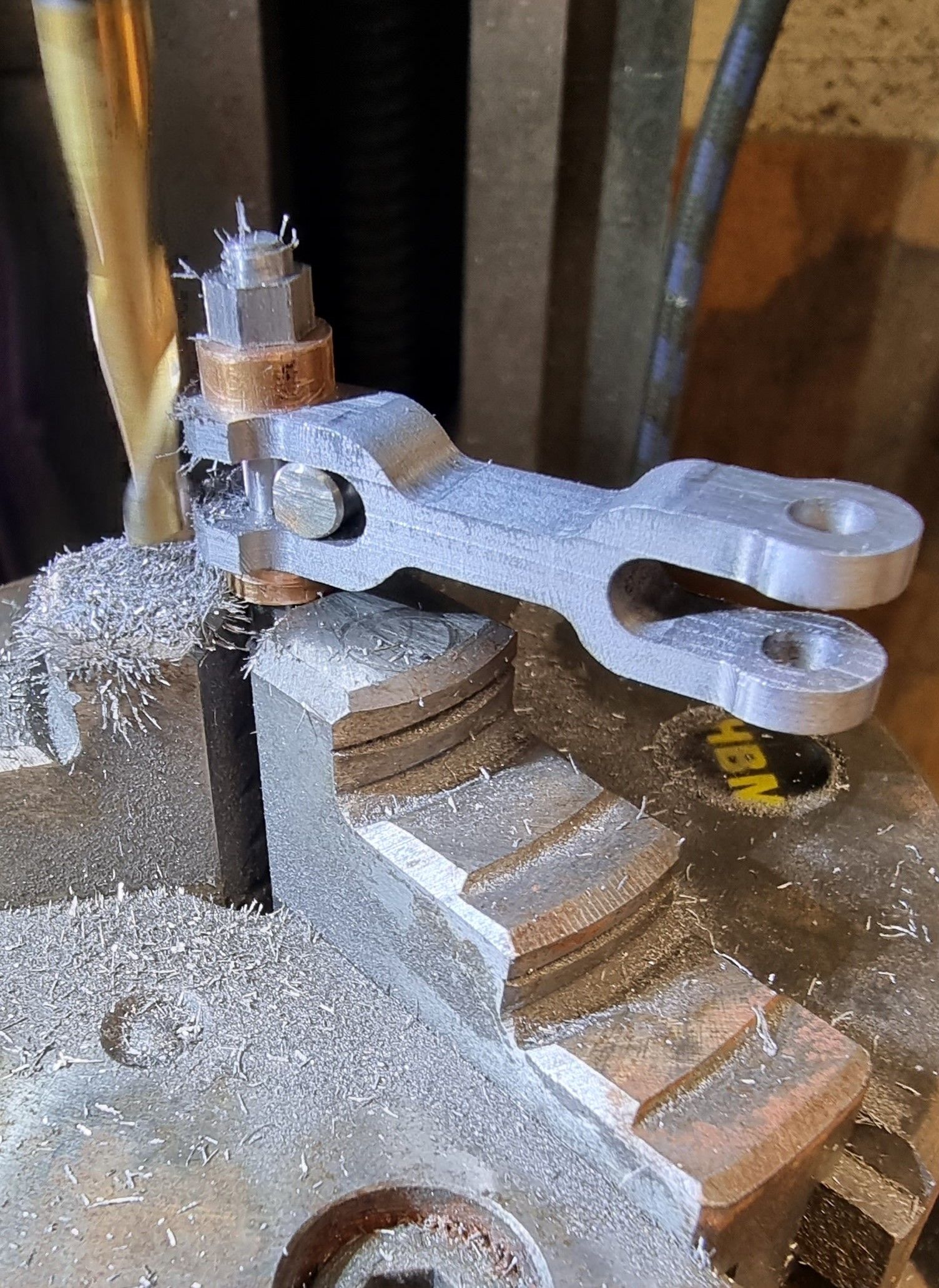
This is an extra operation from what Don's drawing shows, in full size the union links have a step in on the outer ends which is very prominent to the eye. I have included this but not as deep to keep the required strength. This is why I left the middle a few thou oversize to offset some of the loss in structural strength from doing this.
The last machining operation on these was the flute, for this I used a 13.5 x 4mm cutter, I couldn't find a 5/32 cutter with a small enough radius. The flute was machined in the same setup seen in the previous picture. here i show both union links after machining awaiting their final polish although as can be seen the sides have been blended in.
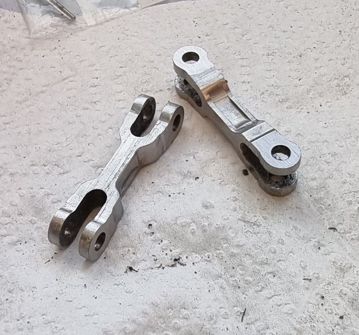
The left hand union link tried for size, I have only used offcuts of 5/32 rod here, the next job will be to make the proper motion pins and their castellated nuts with 1/32 split pins to secure.
Once the pins are made and fitted I plan to work on the valves, get them in running trim (little tight just now) and then fit the bobbins. I can't time them until the last of the motion is made/fitted but I can get them in place and ready. It looks like I can fit the rear valve guides permanently as everything from now on can be done from the front ( advantage of using Jim Ewin's bobbin design) and I can easily remove the rear valve crosshead with the guide in place if required.