
Although these are a pretty simple part to machine from solid there will be a good few different set-ups involved, plus added complications of changing the design to be more prototypical, so I best get on.
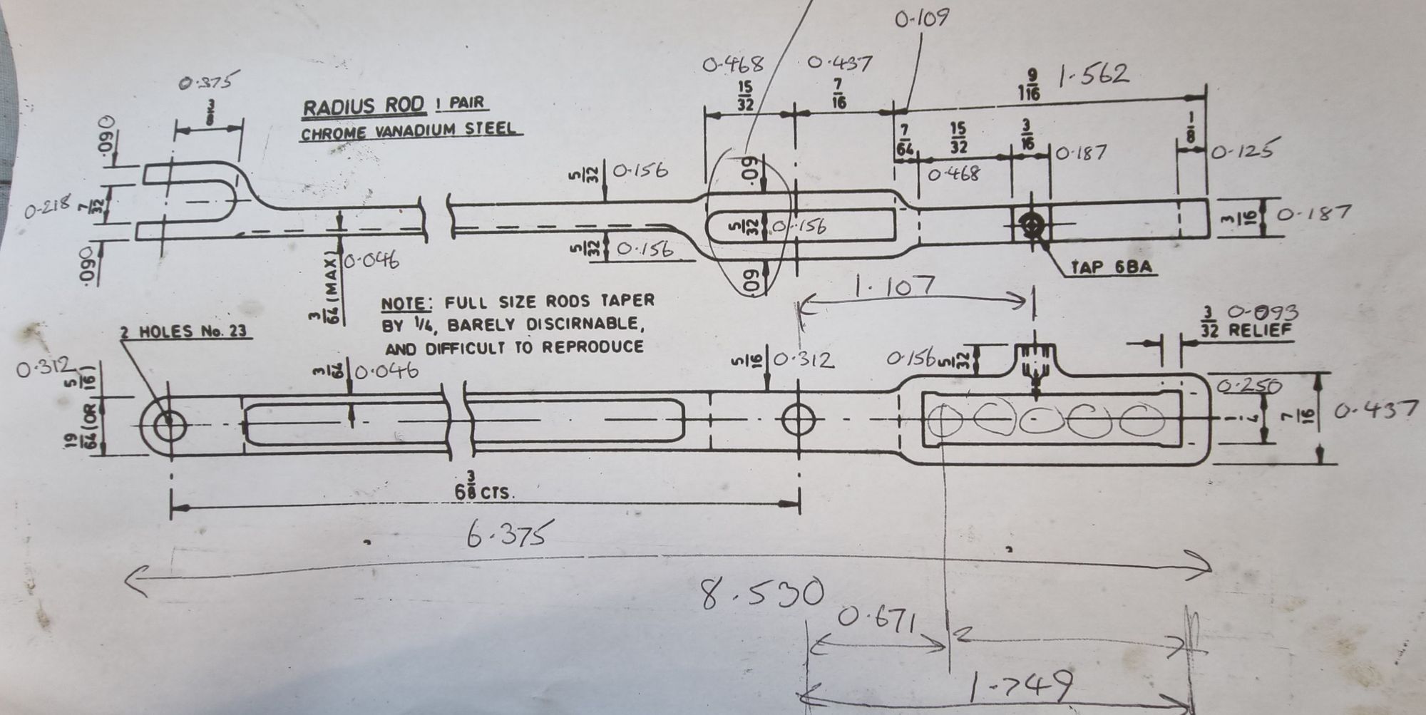
As per usual we begin with Don's drawing, it's close to full size but with some subtle differences which I'll take a close look at to see if I can incorporate them into those for the model. The main difference is around the knuckle which fits around the expansion link, also Don for some reason has the tail for the lifting arms offset whereas, in fact, it was central to the expansion slot. On looking at what has been built so far I think that I can follow full size here without issue. I have converted the drawing to decimal as can be seen by all the clutter, you should see it now.... notes everywhere...:)
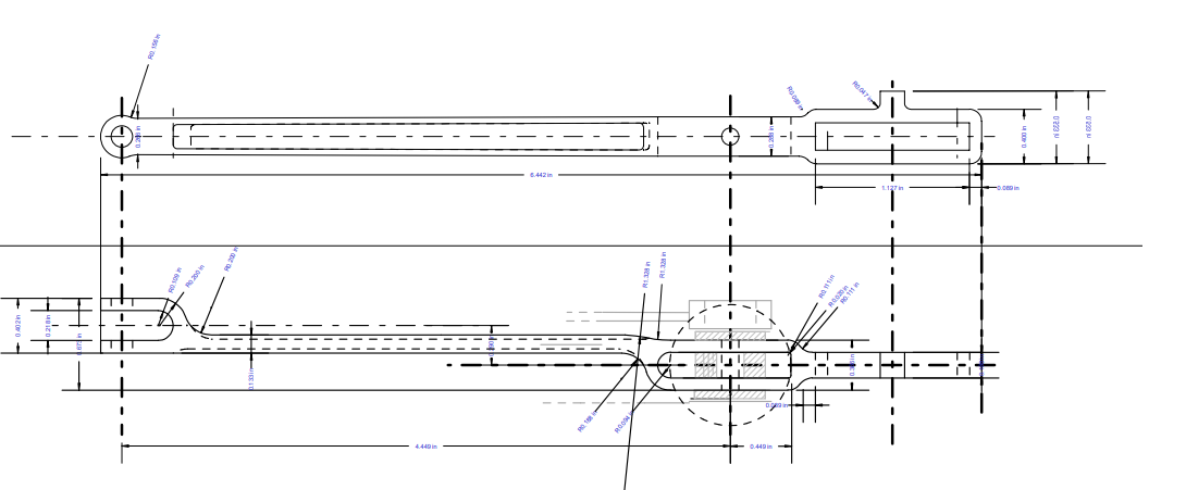
To give some idea of how the rod should look this is a drawing of the K3 rod (kindly sent by Eddie) which is more or less identical except for its length and the offset between the expansion link slot and the combination lever knuckle. Other than that it gives me a good basis for making the rod for 4472.
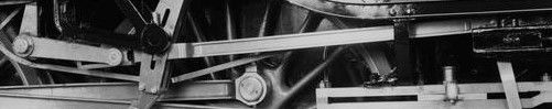
This is FS today, my photo taken in 2016 at York confirms how the knuckle is offset inwards towards the frames and not as Don has drawn.
With a little manipulation of both knuckles, if required, it looks like I can get a rod that's much closer to the original and still fitting the center distance between the expansion link slot and the combination lever which of course is critical measurement.
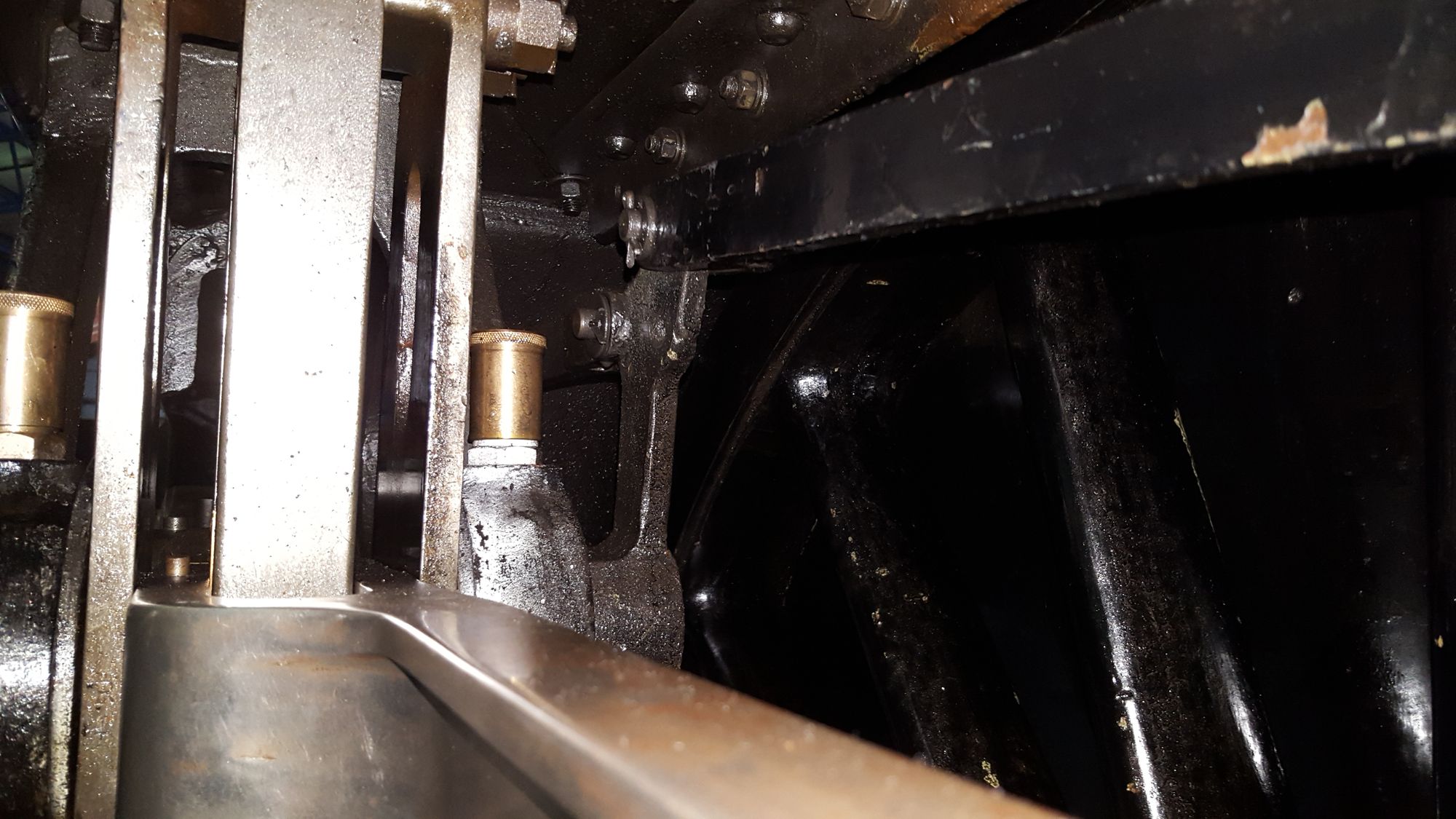
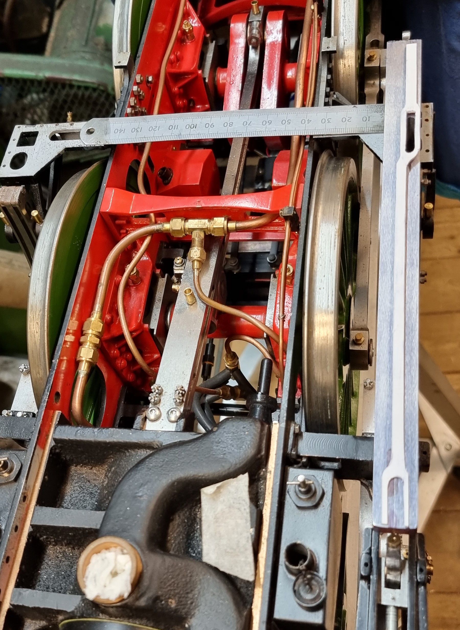
The picture below shows using a length of 5/8 sq gauge plate that I have already machined the 5/32 slot for the expansion link. Actually, I used a 4mm cutter for the slot to give a tiny amount of clearance around the link. 0.1562 for the link vs 0.1574 for the slot, if it needs more, a little fettle using a file should be a painless affair. As can be seen, I have cut out from styrene a very rough profile of the rod to check that all will fit, the considering factor here is that the rod still fitted through the slot in the outside motion bracket which it does, here I am using the profile ( sitting on top of the L/H rod blank)to see how it looks with the machined/marked centers for expansion link and combination lever knuckle slots. This photo gives a good idea of where I am heading, on the full size the outside edge of the rod from the expansion link is straight including the combination link knuckle, you can see that for now, I have pushed the knuckle out a little, ignore that the knuckle arms are different sizes, I did say it's just a rough cut profile..:) If I want to bring the knuckle flat against the outside edge I had two options, make the rod slightly thicker or reduce the offset from the expansion link slot which looks to have some room for improvement, I decided to leave this decision until I had machined the knuckle slot itself as that has only one place to go. One promising result of this test is that the tail in the central position looks to be able to meet up with the lifting arms with no issue, I'll take a closer look at this when making the arms to see if the design needs any slight adjustment. I best point out that at this stage I have already cross-drilled the two 5/32 holes for knuckle pin and die block and also have plotted the oil hole that sits on top of the tail, these will become clearer later.
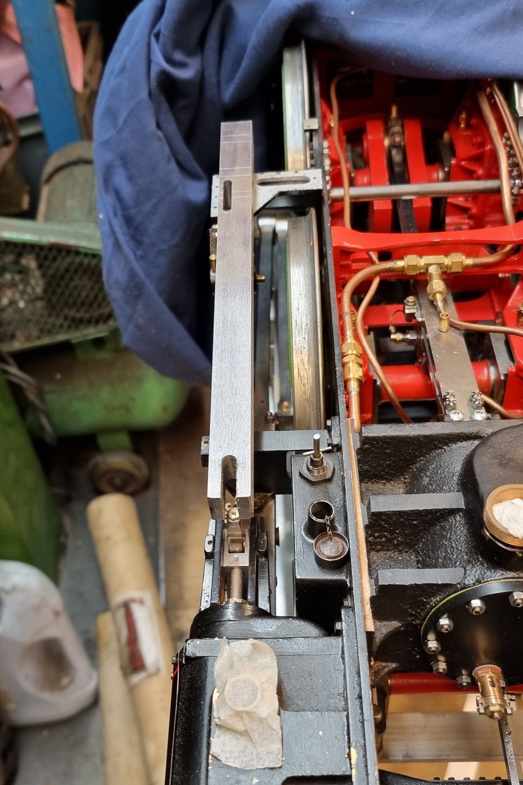
here's the R/H blank with the combination lever knuckle slot machined.
I have called time on this update for now as the next job is to create an awful lot of swarf and this is not going to be a five-minute job, so here's part 1.