
It was now time to create a lot of swarf, I guess there can be a number of ways to tackle this, this is how I did it with the tools to hand.
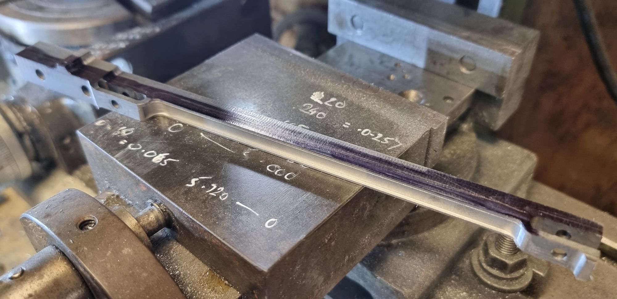
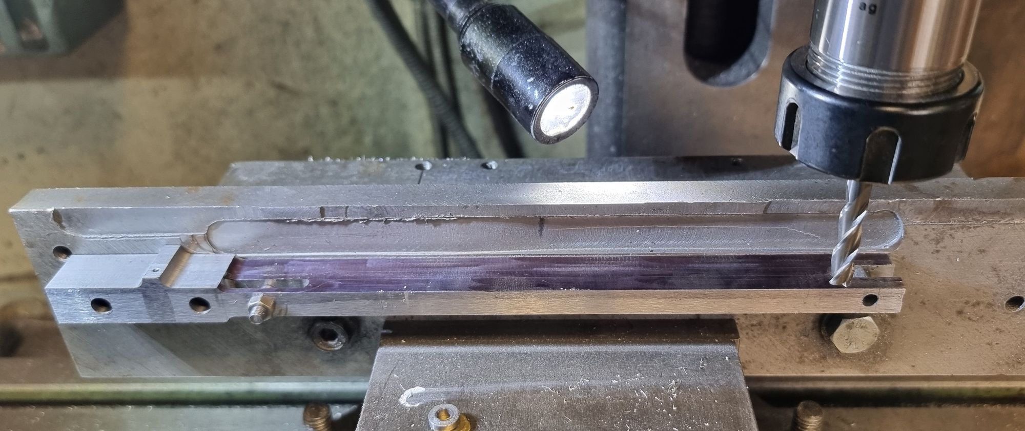
The trusty heavy jig comes back into play with new holes drilled/tapped to match the required CLS. The next question was which side to machine first? I decided to do the top followed by the bottom, my reasoning being that this meant when it came to the delicate sides, there would be less material to remove. To save some time I first used a 12mm cobalt ripper cutter to remove the excess metal more quickly. Here we see the first pass with the ripper.
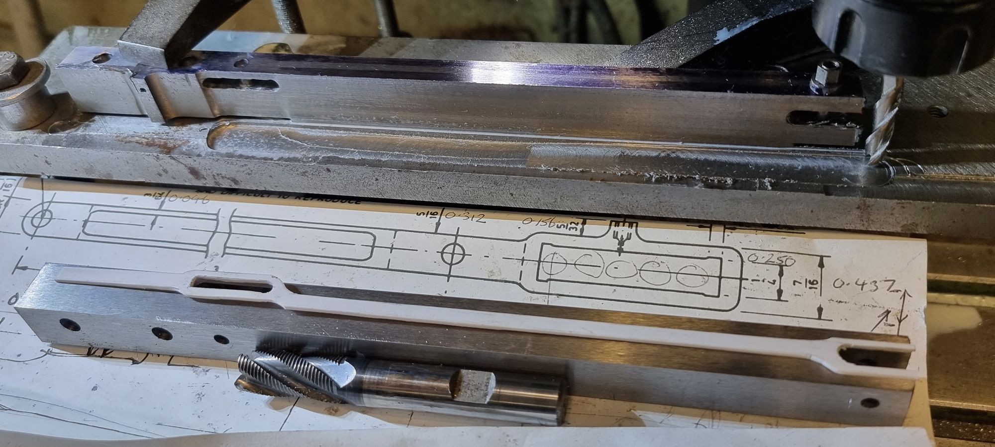
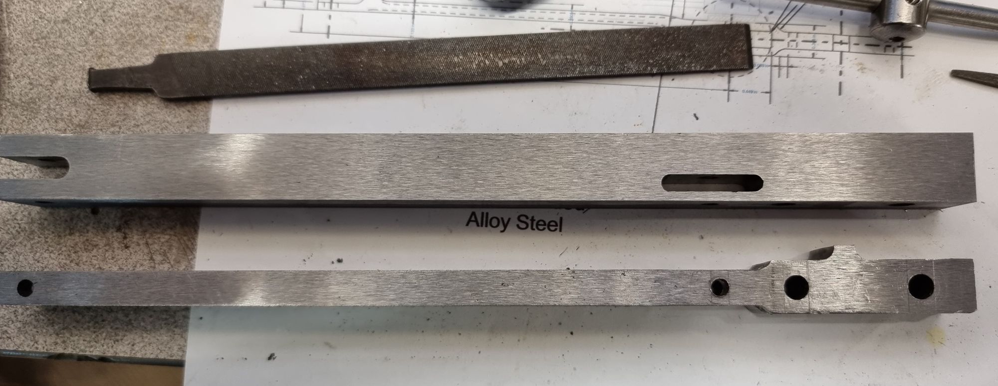
With the excess material removed it was then on to a 6mm carbide cutter to rough out the general profile leaving it a few thou oversize, this was later cleaned up with a new 6mm HSS cutter. The other blank is shown along with a plastic template giving a rough outline of what I am aiming for. It's worth pointing out here that this is where I have differed from Don's drawing. The offset distance between the expansion link and the combination lever knuckle's are, of course, the same. The difference is that whereas Don has made the lever knuckle to the prototype I have made the expansion link knuckle to prototype as this is more prominent than the other. Why the offset is different from the prototype I have not investigated, Don's clearly done something different somewhere, it's not important here as I have to follow the parts already made. I doubt if many would even notice, I have looked at some other model designs which seem to have the same error?
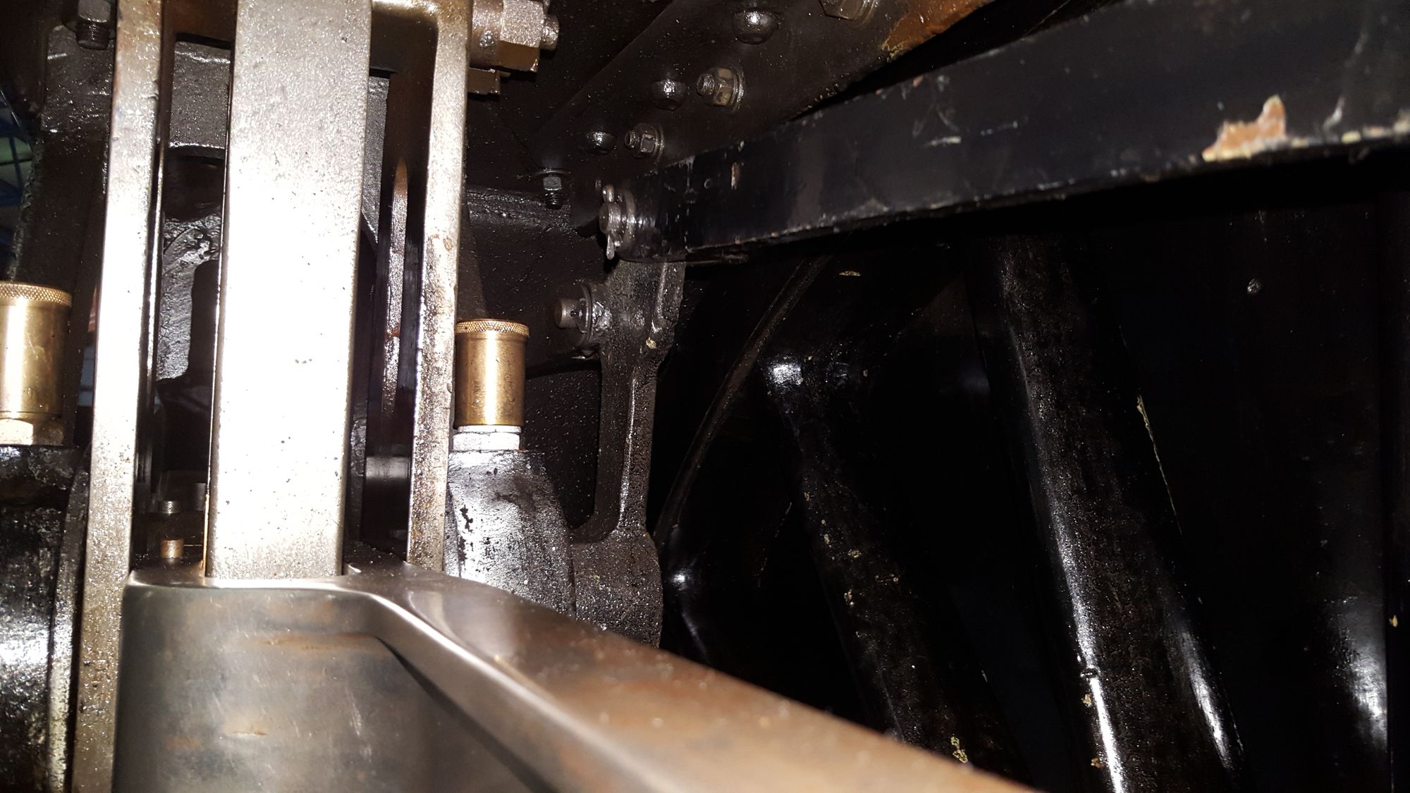
Just so that people don't think that I'm losing the plot, here's a close up of FS's radius rod at the expansion link end, as can clearly be seen, the rod has a dogleg that heads inboard, whereas Don's rod is much more central to the expansion link and also he has the tail for the reach rod lifting arms offset. It should be central, you can see from my template above that mine will be.
top and bottom profiles are now complete on the first blank...
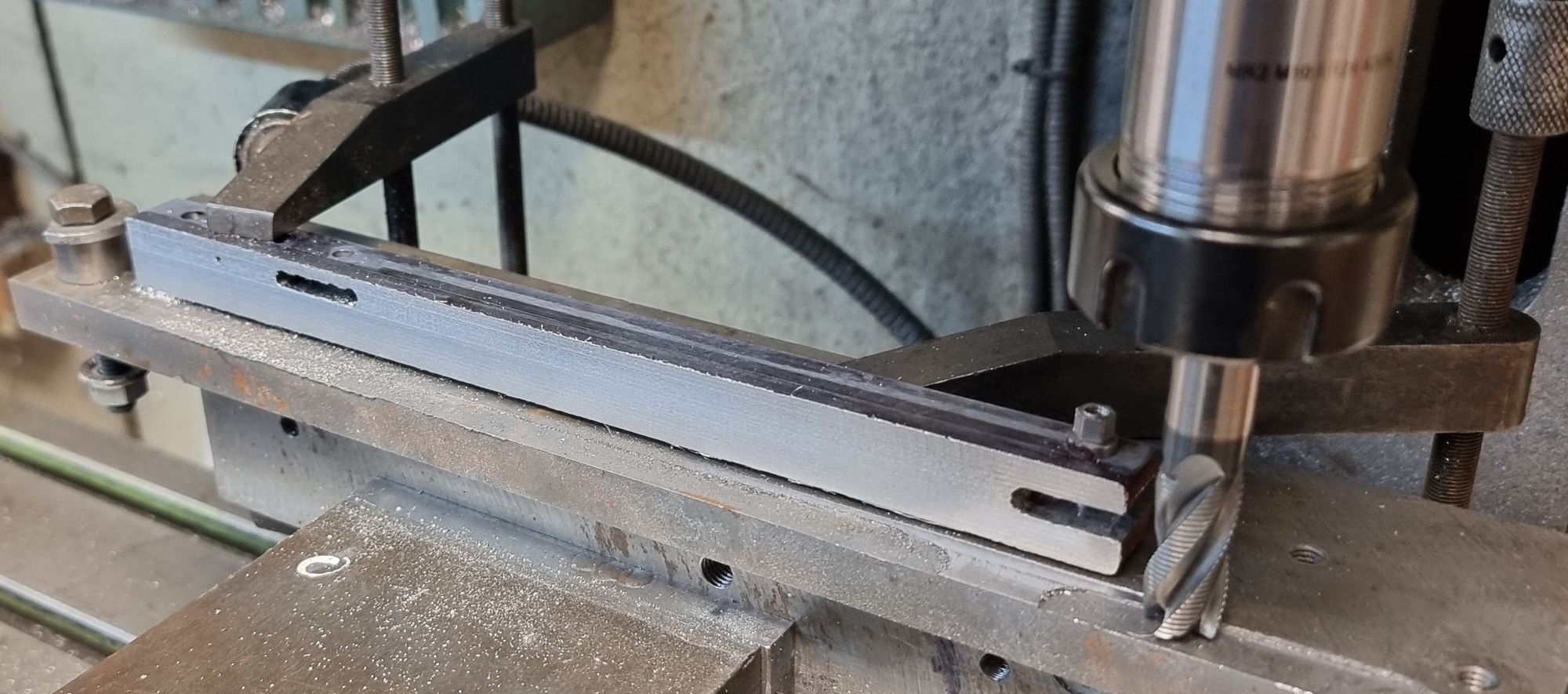
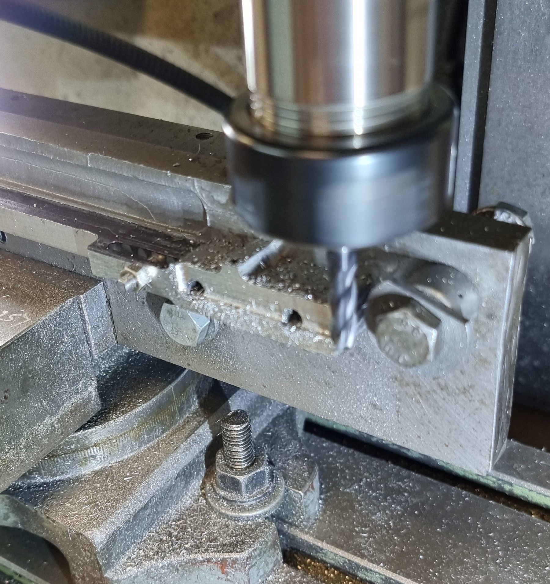
The jig was then clocked 90 degrees in the machine vice ready for the side profiles, I decided to start with the outer side as this is where the flute will be and I wanted to have a good solid lump of steel behind this for support when machining the flute. Note that the front knuckle is now held by a shorter stud with the nut in the fork to give me access to the outer face.
With the middle section close to shape, I then moved on to the tail, again using a 6 mm ripper before finishing with an HSS cutter. As can be seen, I am leaving the lifting arm slot till the end, it will be easier to do when it's at its proper width of 3/16.
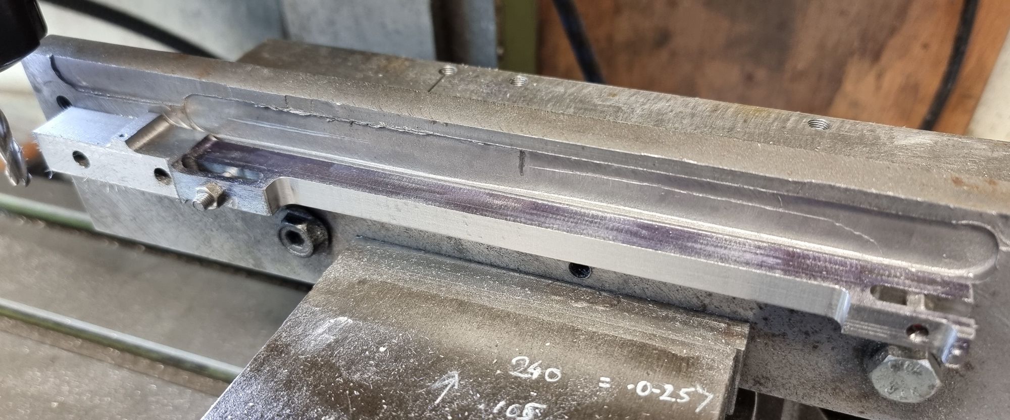
The front face is nearly there, note the small lump left at the knuckle end (right) this is so that when I turn the part around it will be easier to get it sitting square to the jig before machining, the center gap will be packed out.
Now, before doing the flute I needed to get the curves finished around the knuckles, there being 3, two on the expansion link end and one on the combination knuckle. There will be a final rad to machine around the knuckle on the other axis which will be one of the last jobs. So we move to the rotary table.
Lastly, for now, the flutes are now done, I didn't have a cutter (5.5mm)of the correct depth so stepped it using an IIRC 20mm x 4mm cutter. You should be able to see the lightly scribed lines for the other side, I need to make a few adjustments to the jig first, to be able to hold the part securely, that will be next time.
