

Today I begin some of the more interesting parts to the motion, I say 'interesting' in as far as they take a little more thought in the setup. There aren't many more parts of the motion to make but those that are left bar the union links are shall we say a little more involved. We have the combination lever, radius rod and eccentric rods plus the various bolts/nuts to connect them. There will be a few bits and pieces still to do before we can run on air but nothing too taxing.
The combination lever could be tackled in a number of ways, I have chosen to make them from solid gauge plate. As stated before all of the motion on this model are either HRPO steel or gauge plate, the cost is a fair bit more but I think it's worth it.
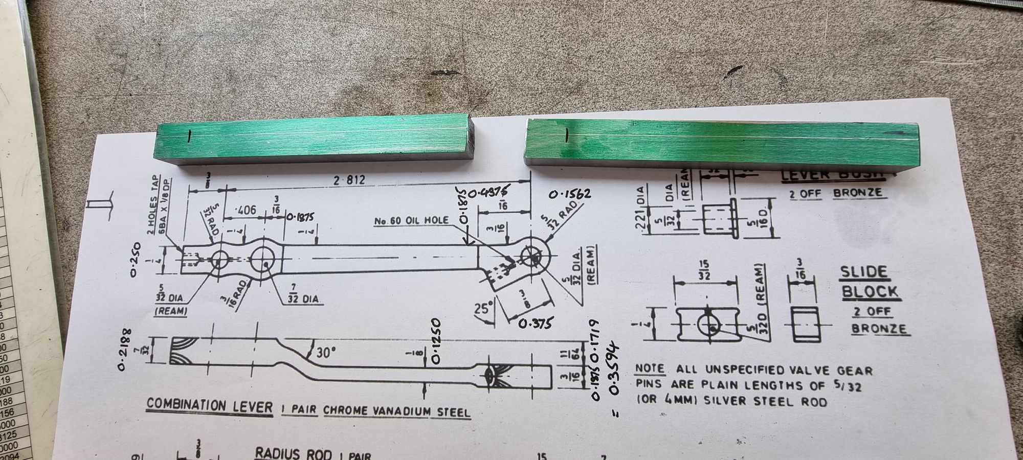
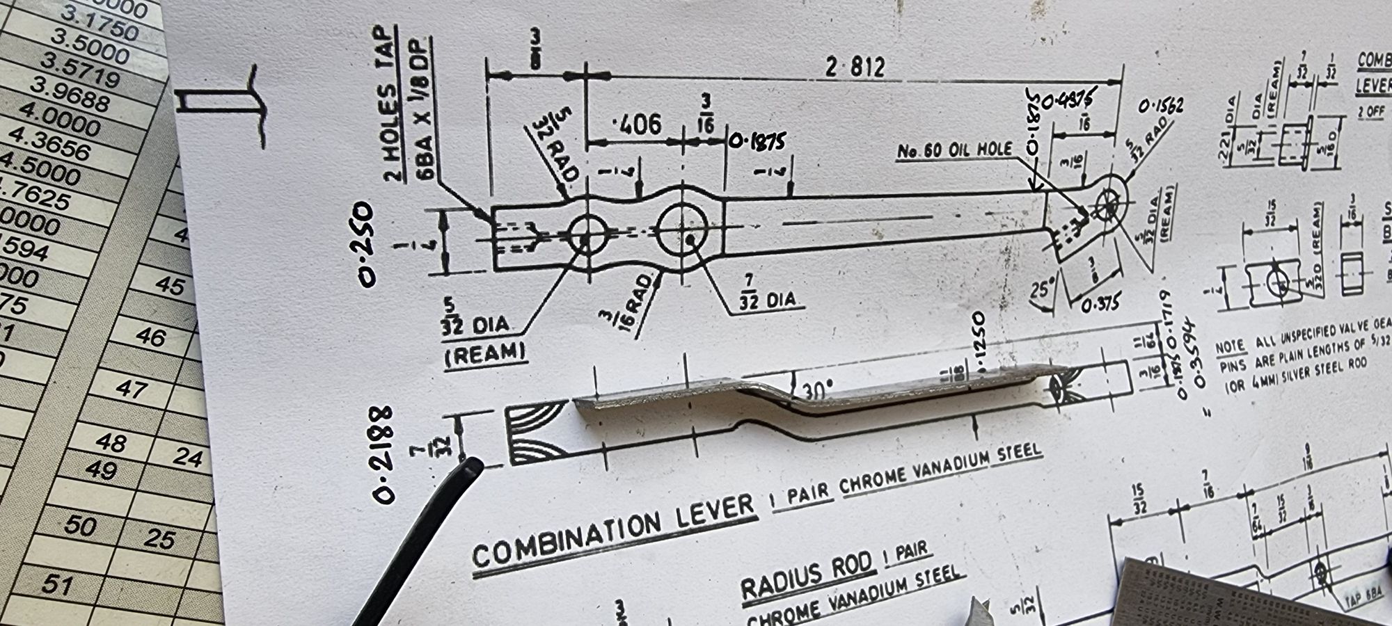
I'll begin with the drawing to show what we are up against, nothing too complicated but as I said, setup and the sequence is important.
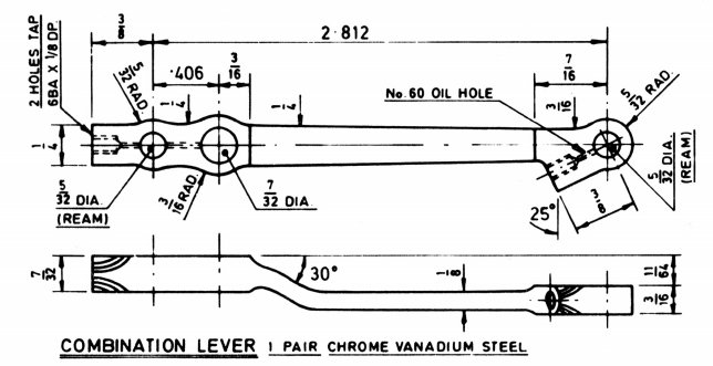
The first thing to do was to cut up some 1/2 x 3/8 gauge plate into suitable lengths for the job in hand. Note also that I have written the decimal dimensions on the drawing for machining.
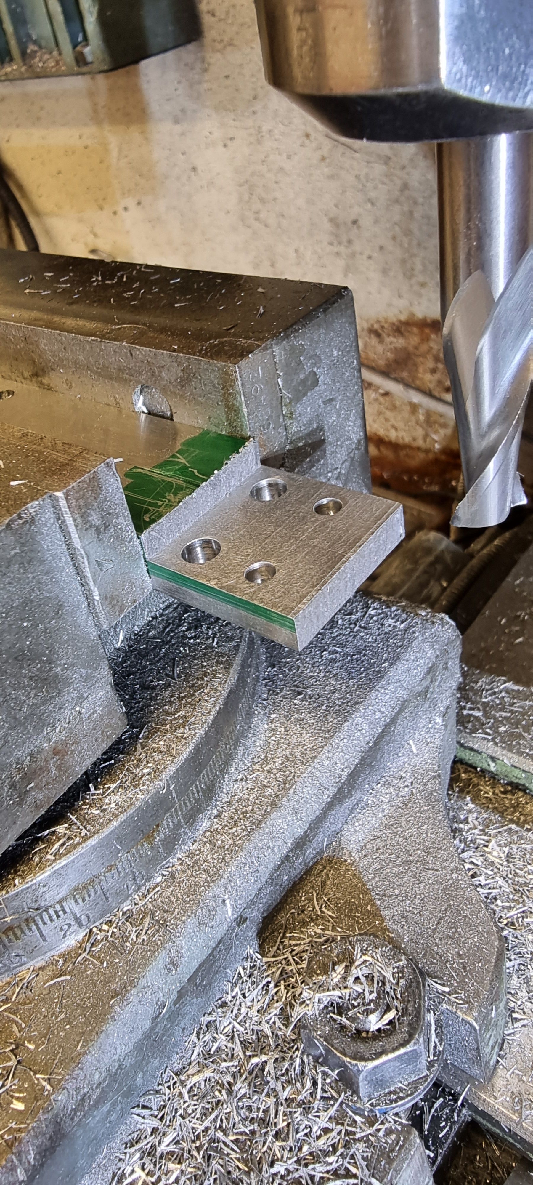
The three holes were tackled first, the middle one is 7/32 and the two end holes are 5/32, all of which were reamed.
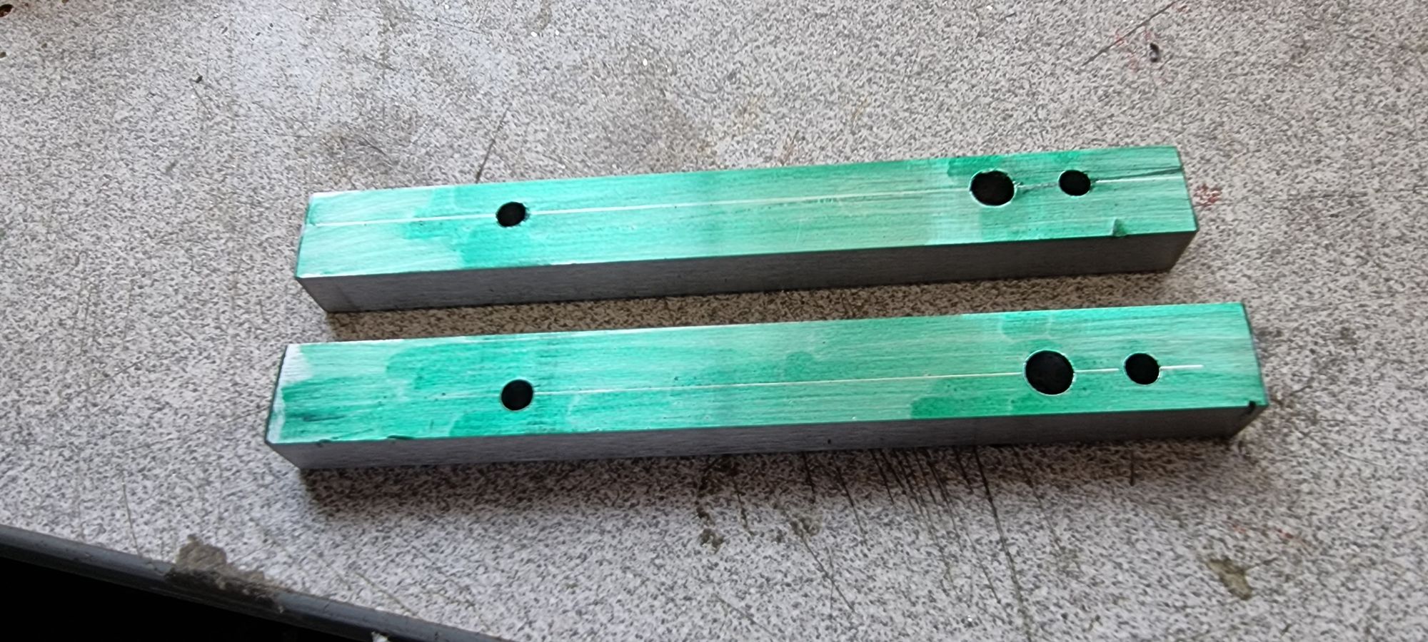
Here are the two blanks ready for the machining to begin, note that they are handed and that the holes are not central, this is to allow enough room for the oil reservoir to be included in the part.
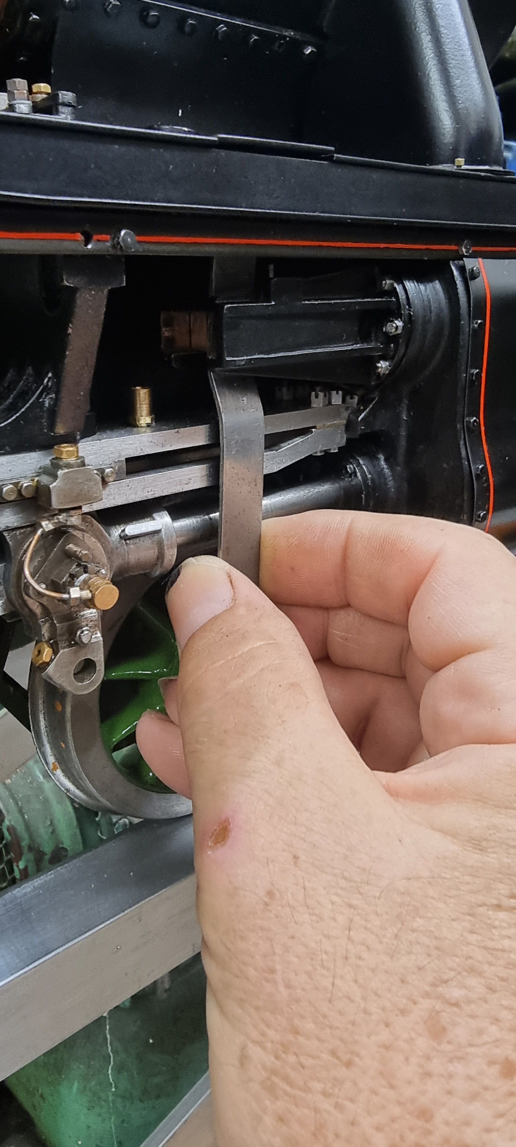
that's it, finished.. haha.. I wish, but in as far as critical dimensions are concerned those are now done, all I need to do now is make the shape and this is where the fun begins. Before doing anything I decided to check the angle as drawn and see if all is as it should be. Taking a piece of 1/16 steel strip I bent it to shape to match the drawing along it's back edge. NB: the drawing is overscale, all I needed here was the angle.
I then held the piece where it belongs to see if there was any obvious errors, so far all looks good. The actual combination lever will be 1/8 thick where it bends so I think we have enough clearance, time will tell.
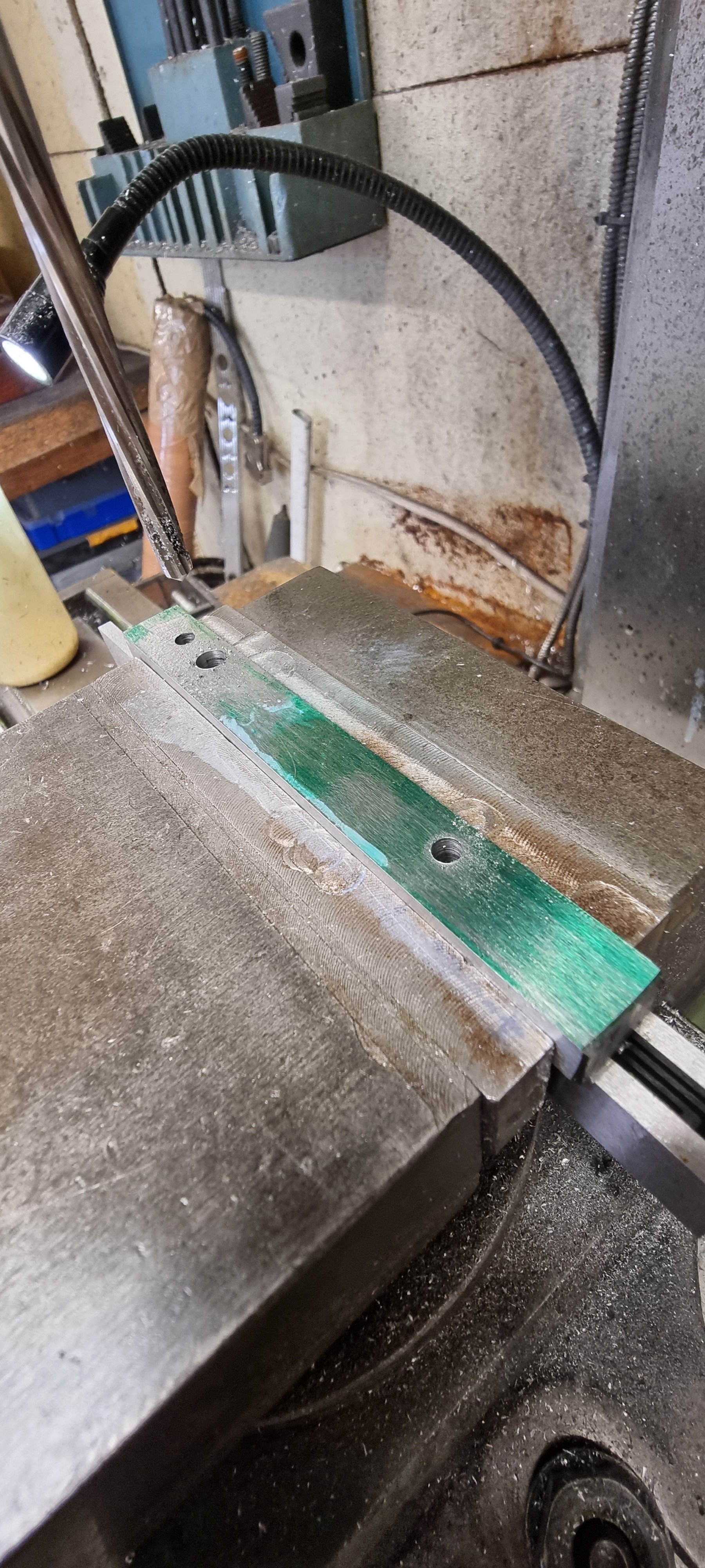
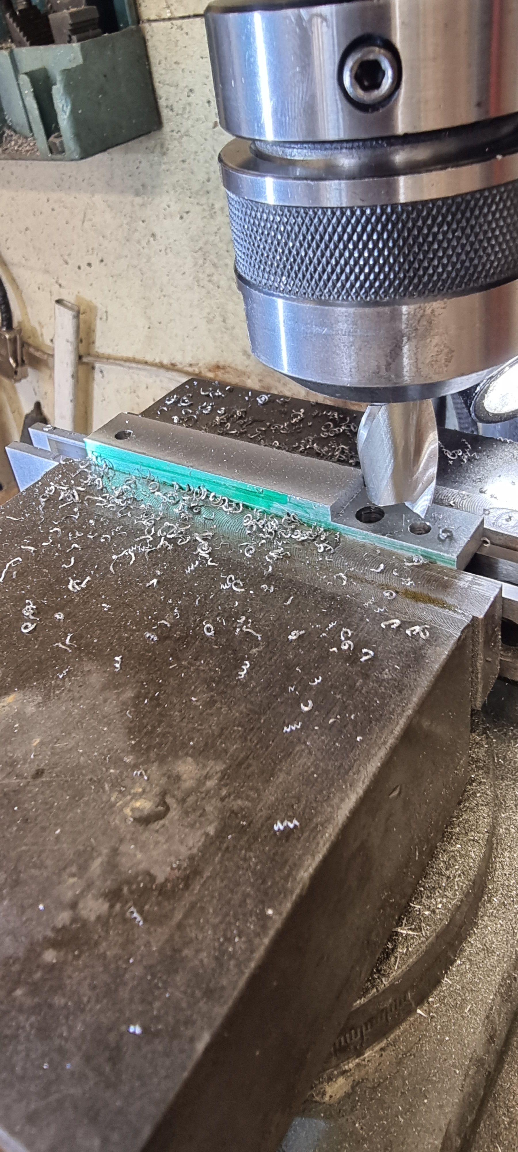
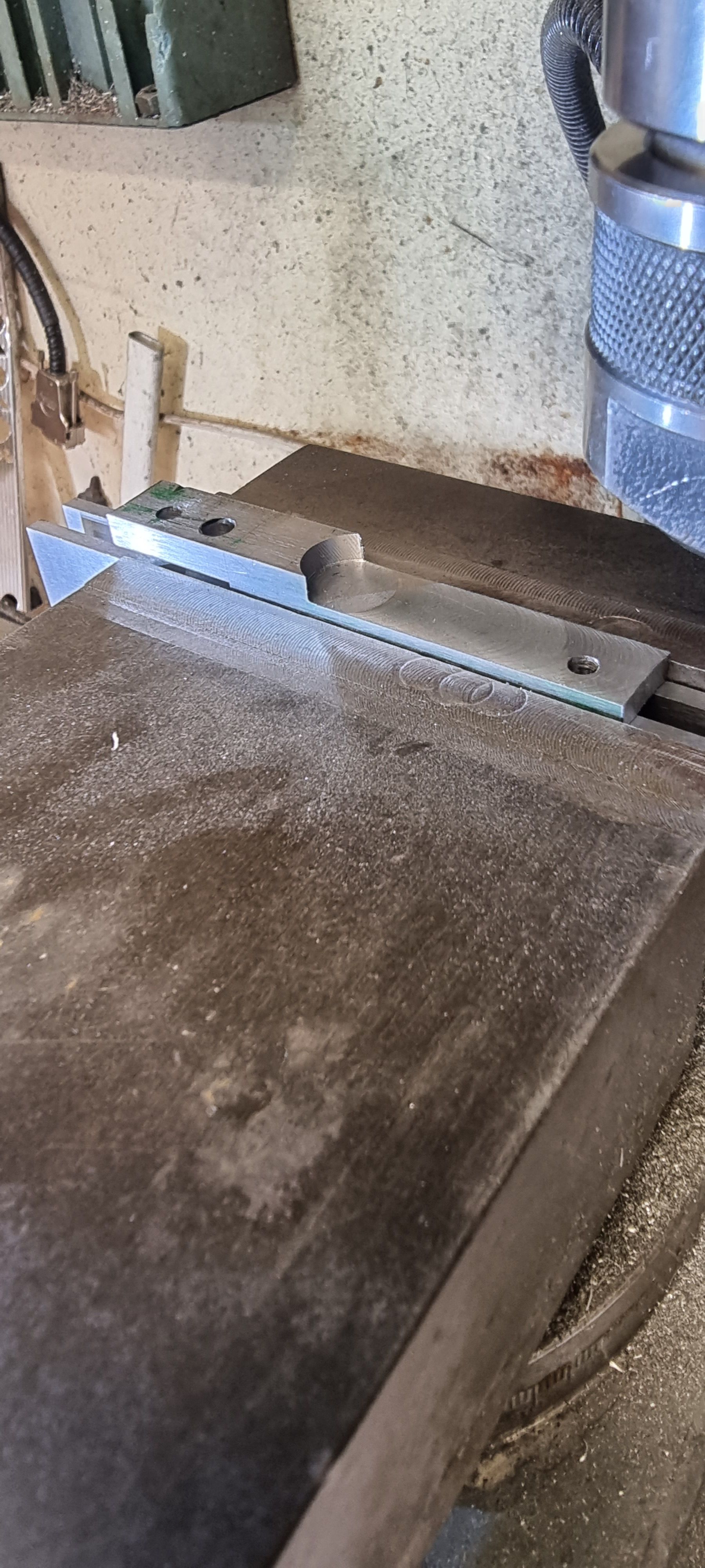
Ok, so to begin the machining I have taken my datum from the rear face and started by machining this 7/32 wide section to just short of where the 30 degree angle begins. Both blanks were held together for this setup, they were also faced along the end at 0.375 from the outer hole centre.
I then machined the blanks one at a time on the same face down to the required 0.359, this was to bring the 3/8 material width down to the correct size.
with that done I could now flip the blanks over and make a start on machining the front face, this was done to bring the width down to 3/16 which is the oil reservoir width, the middle 1/8 section will be machined after the angle has been done.
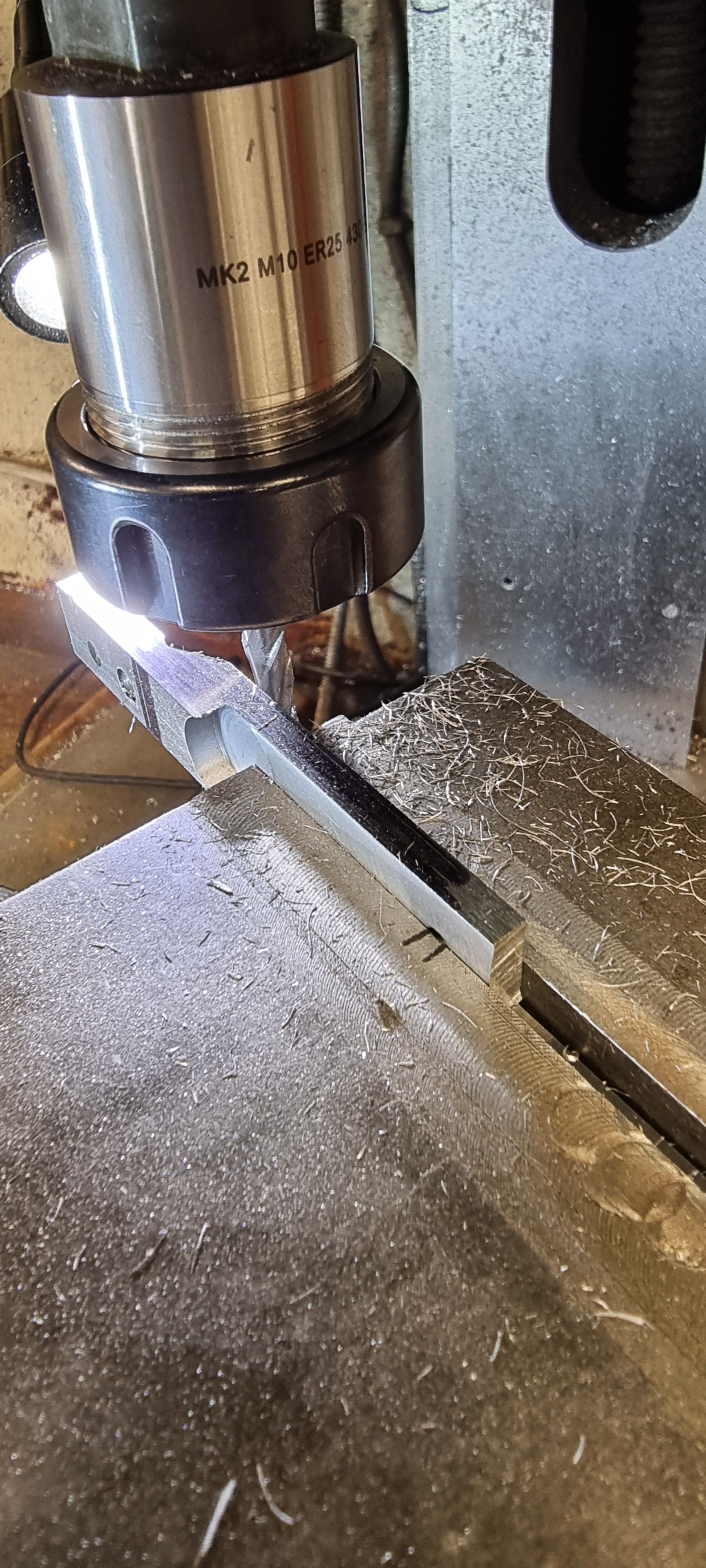
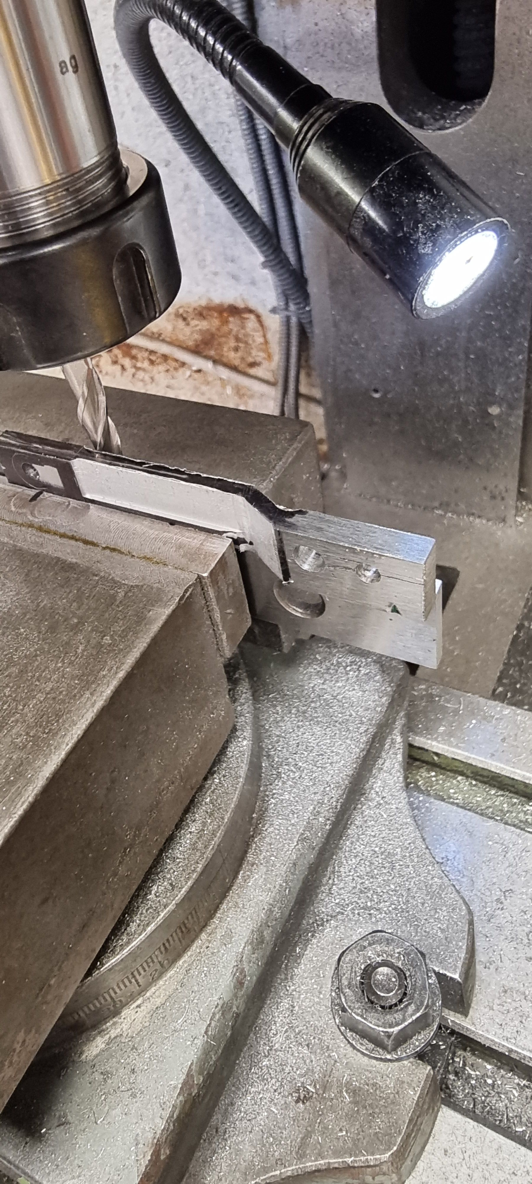
Now for the 30 degree angle, my trusty swivel machine vice comes to the rescue again and it was set using an adjustable bevel gauge to ensure the angle matched the drawing. I start again with the front face and have followed the drawing closely, that is I noted that the angle doesn't stop on the front face and that it actually cuts into it, same goes for the rear. I have followed suit going by eye for now using a 6mm cutter. Note the two pen marks registering the bottom hole, this is to make it an easier task to machine each blank using the same DRO settings.
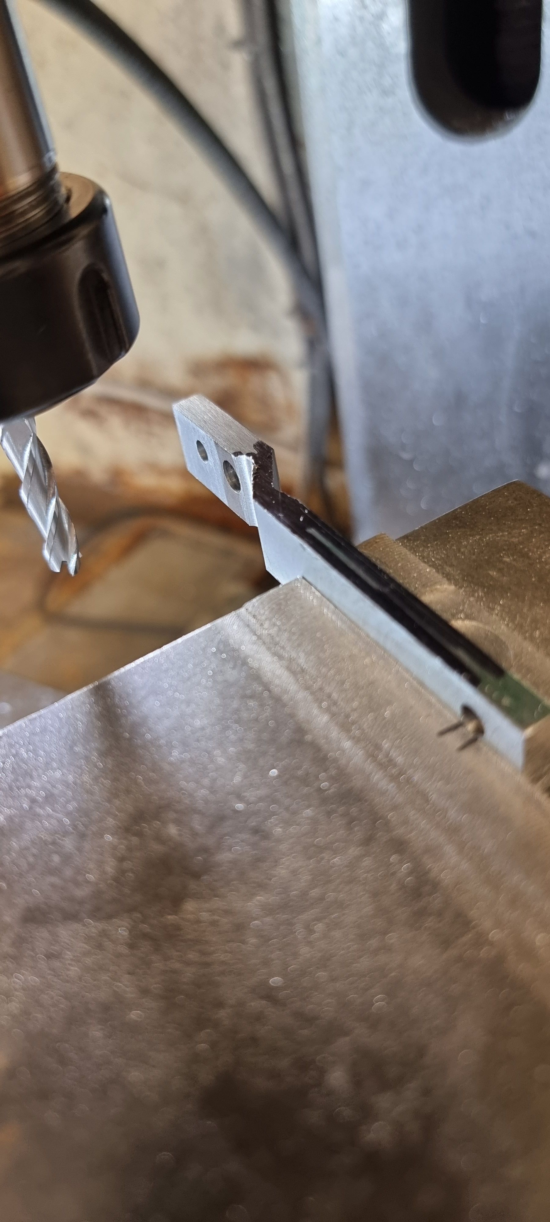
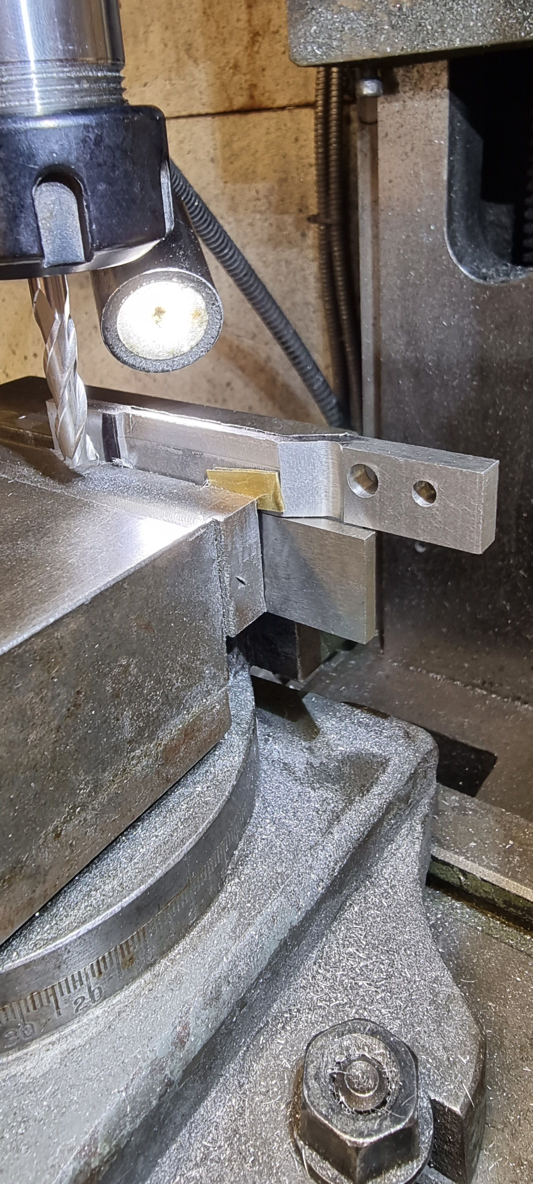
with the front face machined to size the next job was to machine the rear checking that the part left measures 1/8". I took this picture showing the other side which shows how thin the lever is in reality. Don states not to use mild steel here as it's not strong enough, something about a failure at an IMLEC event which I guess must have been in the early 80's or 70's. He also says to be careful with filing as any marks left can be the cause of stress factors leading to failure, I guess Don was concerned about this particular part?
Before moving on to reduce the main length down to 1/8" I did another quick check on how things were looking. I'm happy with it so far, you can never do to many checks.
For this next section I had to do it in two halves, that is I machined over half of each side first as I needed to hold the length rigid in the machine vice, this bit would have too much flex to have it hanging out of the vice.
Each part was then flipped over and using suitable packing the rest was machined to thickness.
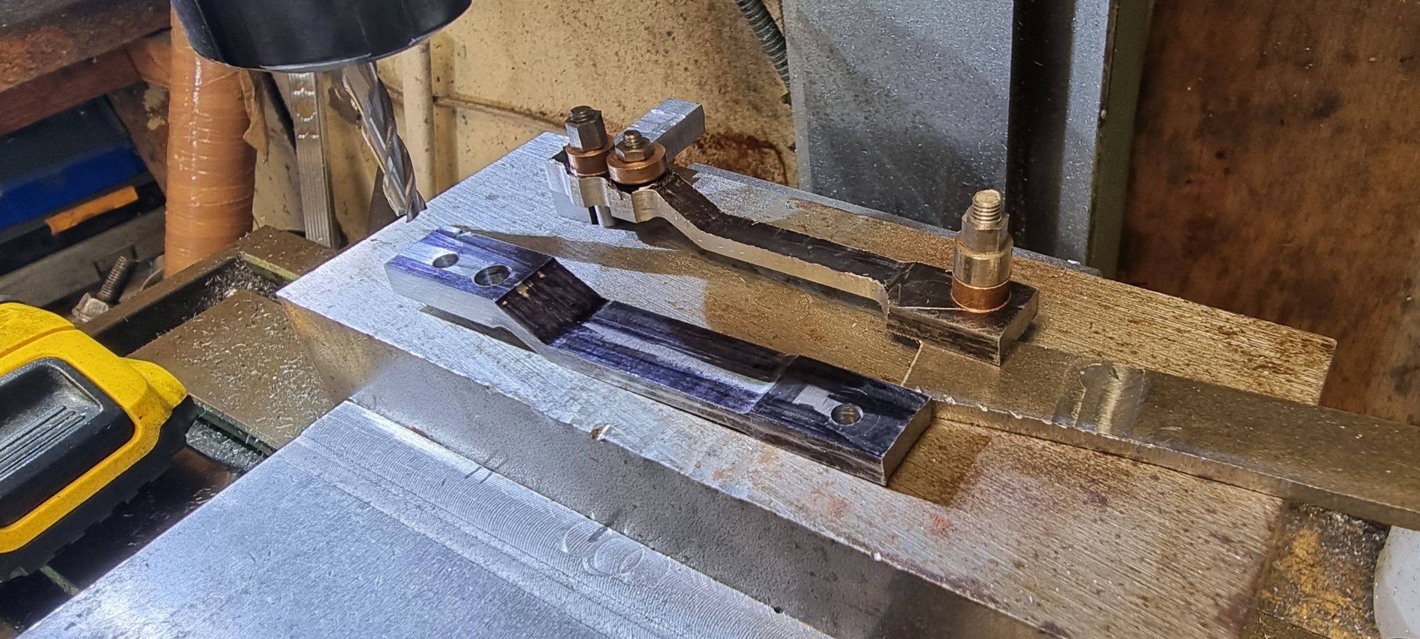
That completed all machining operations for the front and rear faces, it was now time to machine the profile. Returning to my trusted method of using a solid lump of steel, the first lever was bolted to the jig using suitable packing to keep it level. my approach here was to remove all of the access material that was required to include the reservoir and in doing so machine the width down to 1/4 with the holes central to this. It's certainly getting smaller now, before shaping around the buttons I will first need to reduce the width at the union link end as this part is tapered from 1'4" to 3/16". In this picture everything is still parallel, I have included the other side to show how much needed to be machined off.
On to the taper, this starts off at 1/4" at the top and reduces down to 3/16" at the oil reservoir. I started by angling the machine vice by 1 degree, as it turned out this was just what the doctor ordered...Therefore after machining one side as a test I continued with the other, noting on 'X' where to stop to be able to match both levers. I changed the cutter from the 6mm to 4 mm to achieve the smaller rads.
Once both levers had reached that stage it was time to shape the oil reservoir, Don's gives an angle of 25 degrees, so the vice was set for this to do the top of the reservoir, it was then a simple task to machine the return as that was at 90 degrees to the first. Note that the picture does not show the vice setup for this. I have returned it back to 'zero' to machine of the excess tail.
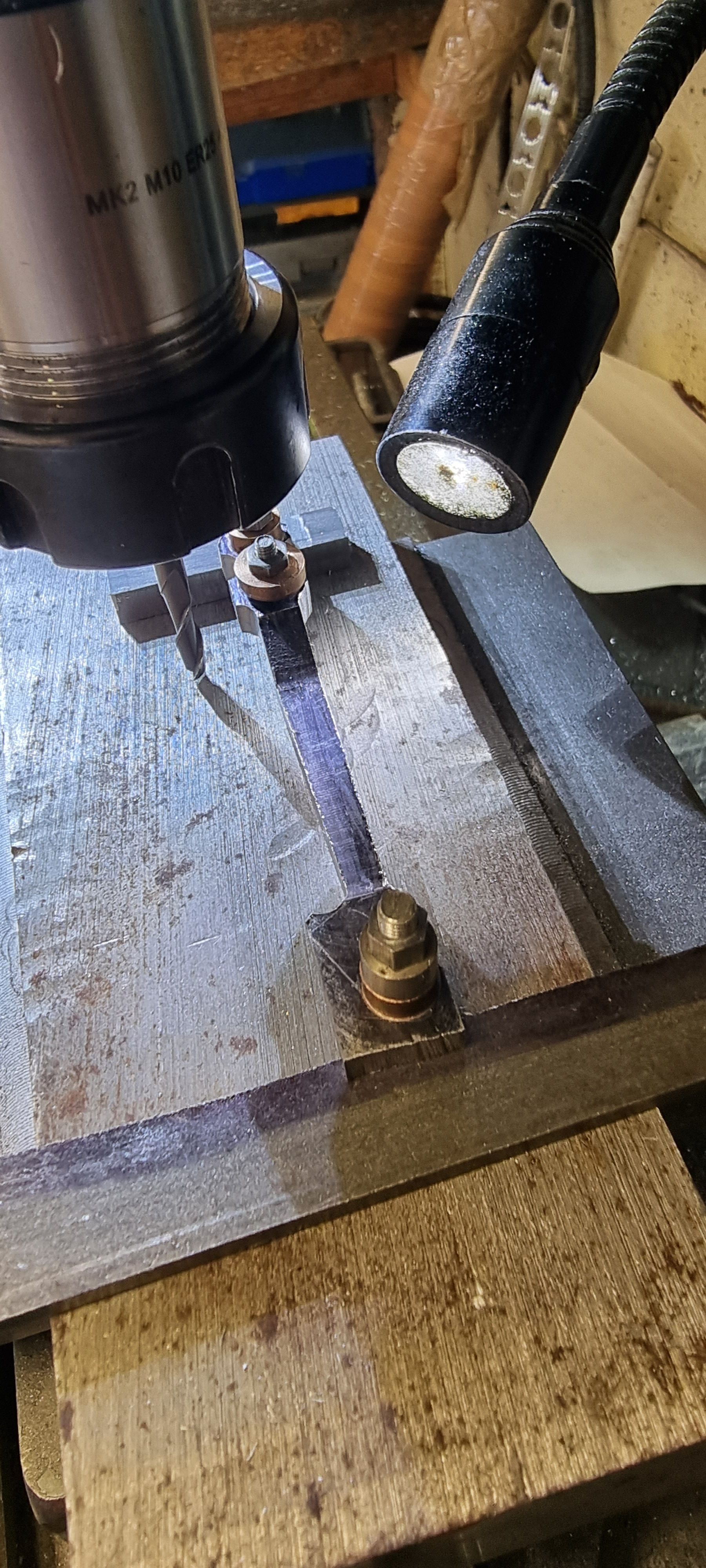
That concluded the basic machining, it was then the turn of the rotary table to do its stuff using the buttons. I machined the two outer ends first using the 5/16 buttons that I machined earlier.
With the two 5/16 outers completed I then machined the middle 3/8 section being careful not to cut into the main body.
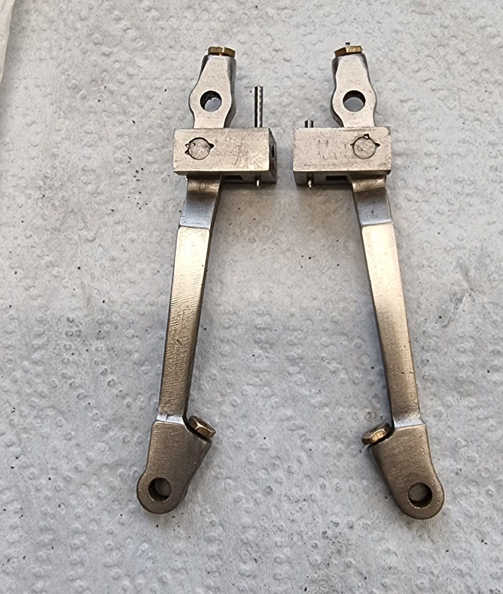
That was it for the machining, after that is was all hands to the files to finish off and give the two levers a polish. I had some more work to do which I'll do once the oil reservoirs have been drilled/tapped but they are beginning to look the part.
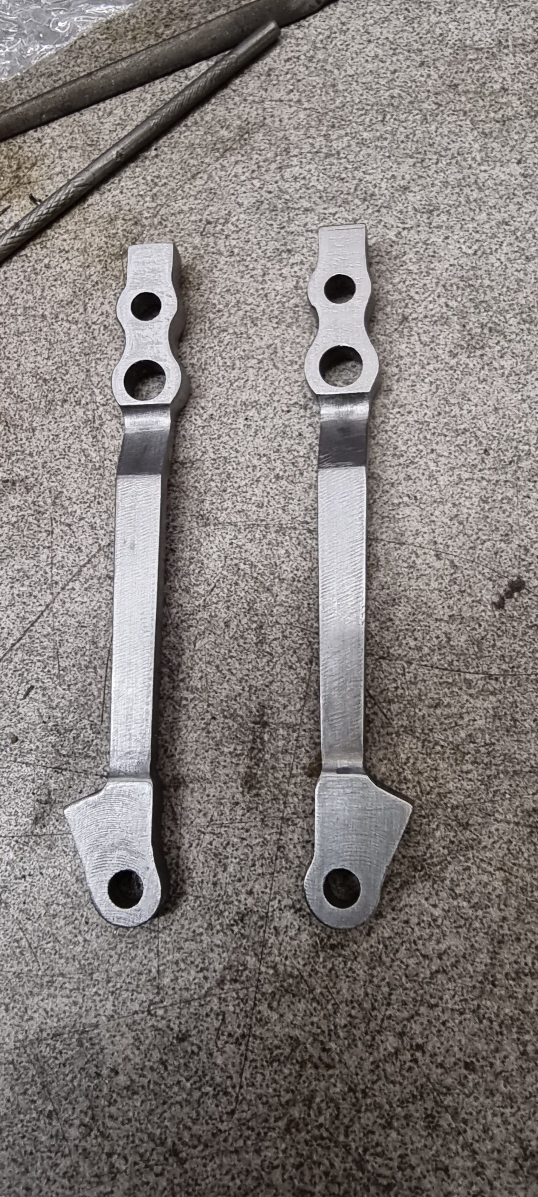
Before tackling the oil holes and doing the final fettle/polish I checked that things where still looking good with the fit, looks like they should work.
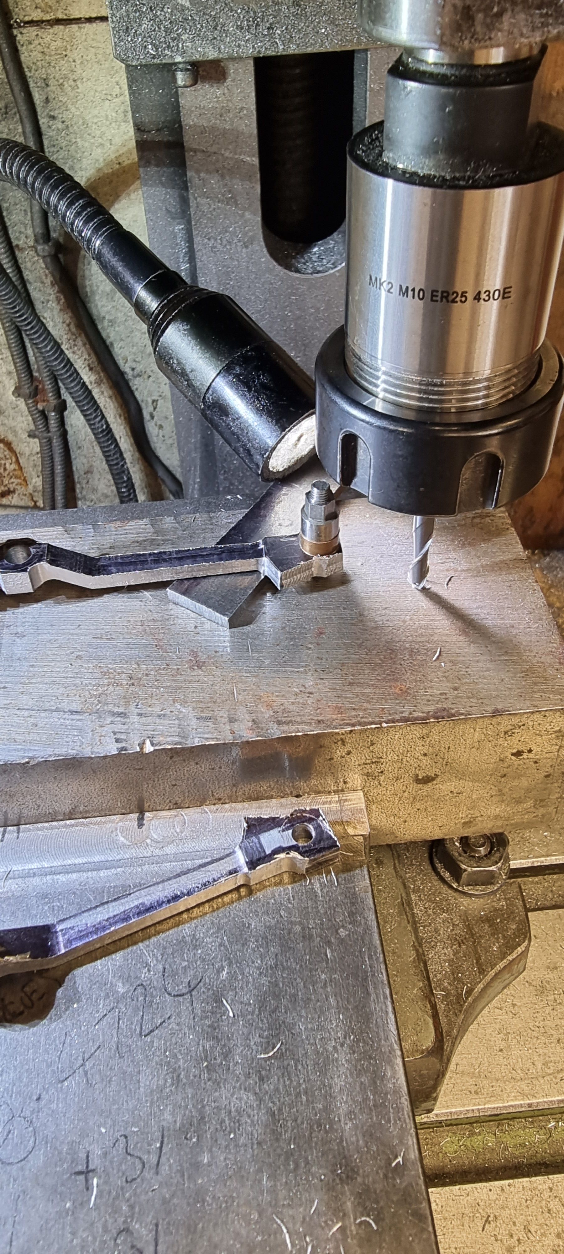
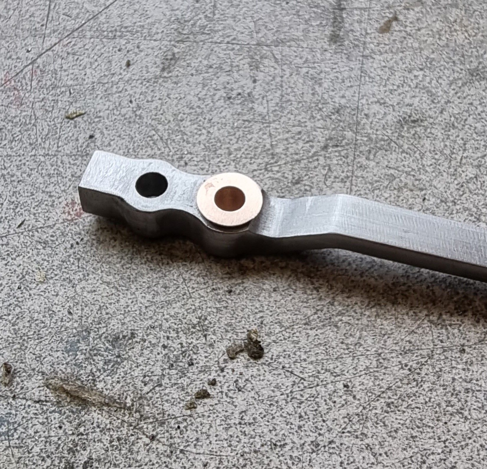
on to the crosshead stepped bronze bush next, this is an interference fit into the 7/32 hole which is 5/16 OD with a 1/32" shoulder bringing it to 1/4" overall width to match the slot in the crosshead. It's the only bush on the combination lever, the other two have no bearings which surprised me a little. Don states to make the pins from silver steel which I believe has an annealed hardness of 27HRC, the tool steel which I have chosen as my preferred motion material in the same state has a harder value so unless I'm reading this wrong, the motion parts shouldn't have any issues with wear and tear as long as well lubricated.
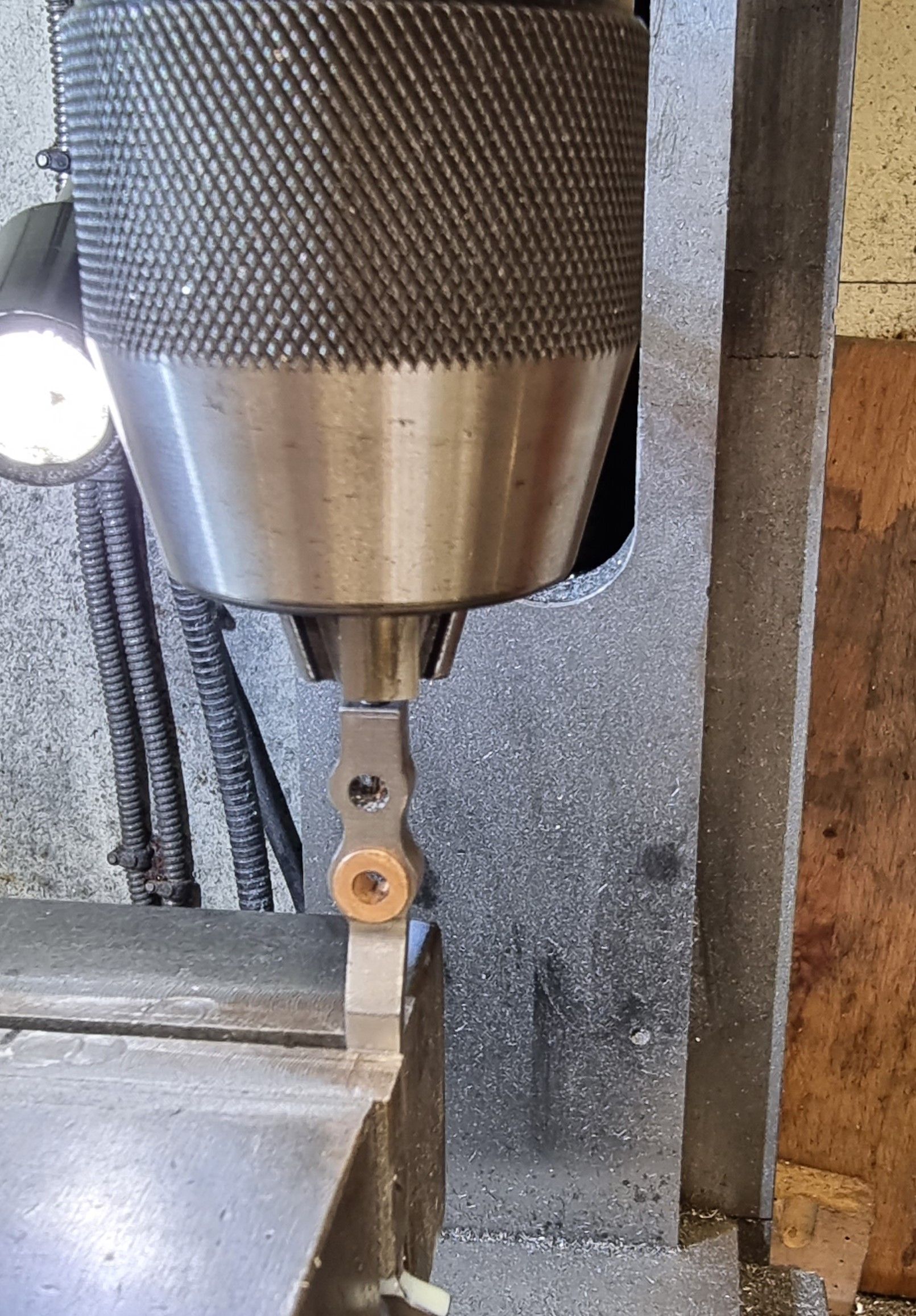
Nearly there now, the two remaining jobs being the oil reservoirs for lubrication, I tackled the two top combined holes for the crosshead and radius rod first. I drilled/tapped the oil reservoir 6BA to a depth of 0.200 and drilled the small 1mm oil way using a cobalt drill. The photo shows that the small oil hole is drilled through both 5/32 holes as one.
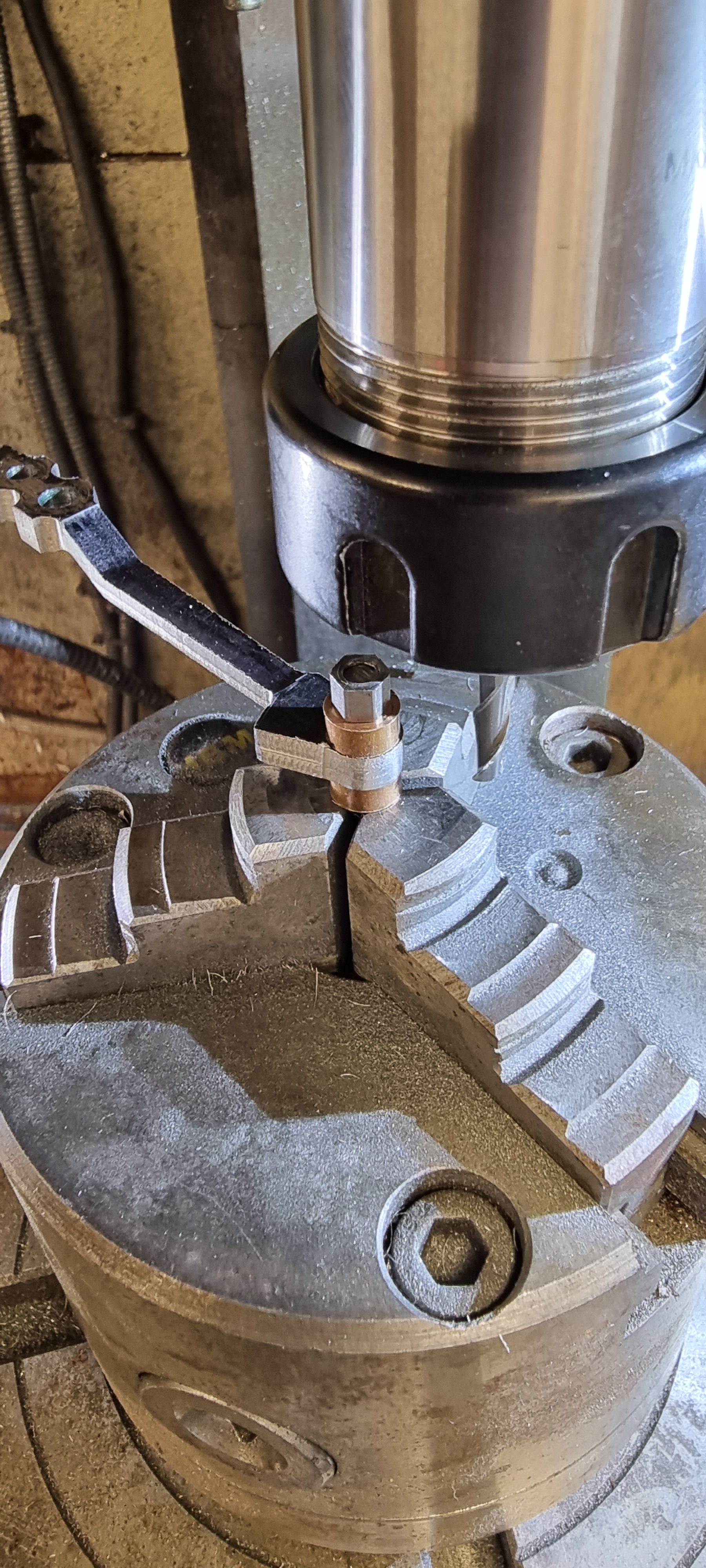
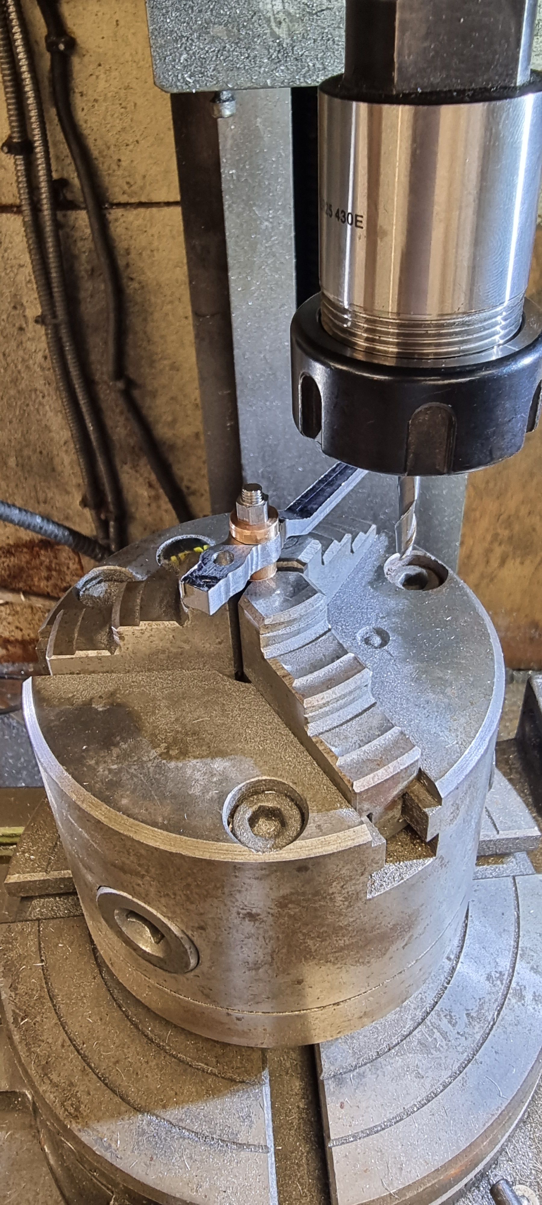
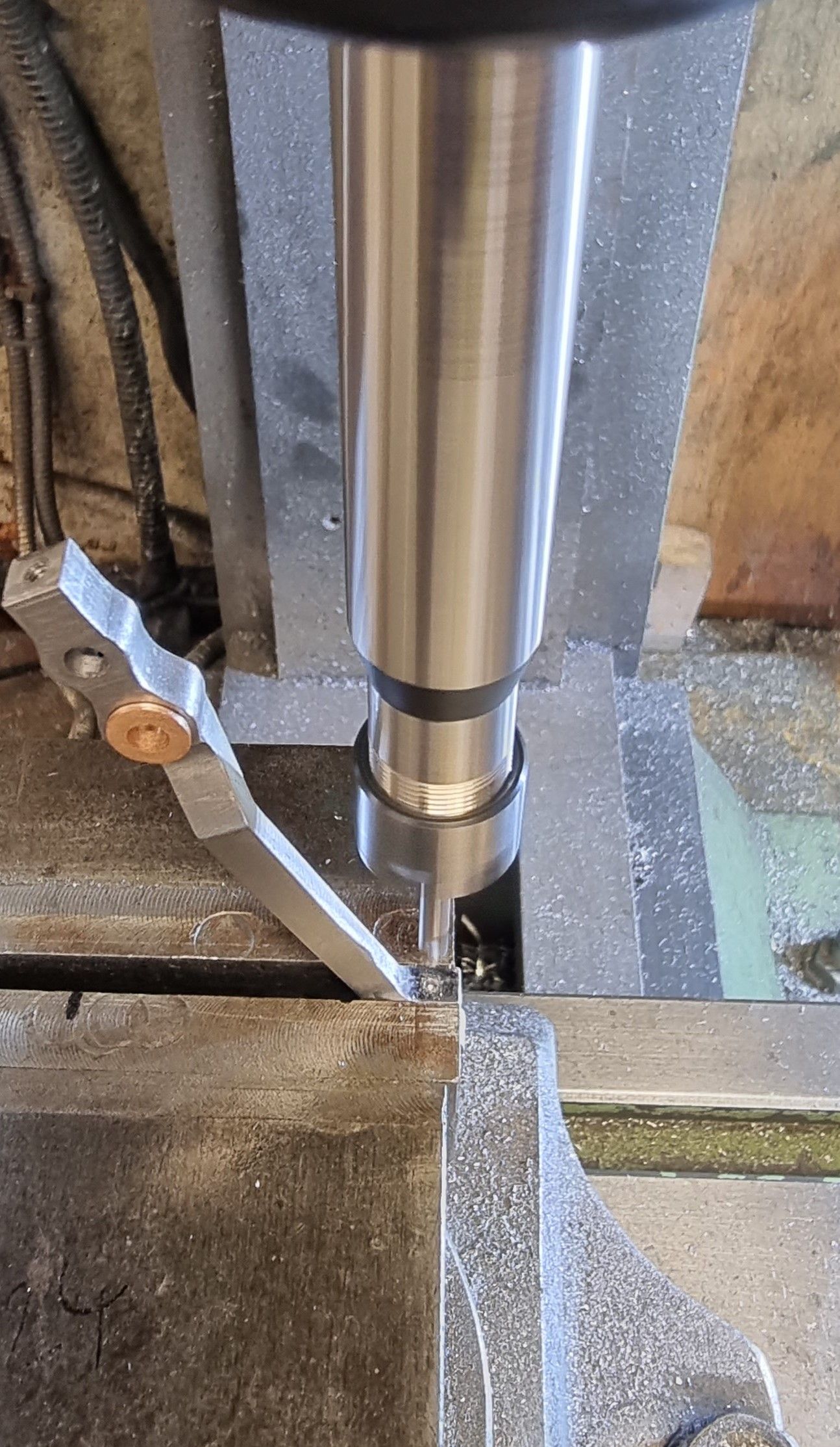
It was then the turn of the union link oil reservoir for which I changed the chuck to a small collet chuck so that I could reach without risking any damage to the lever.
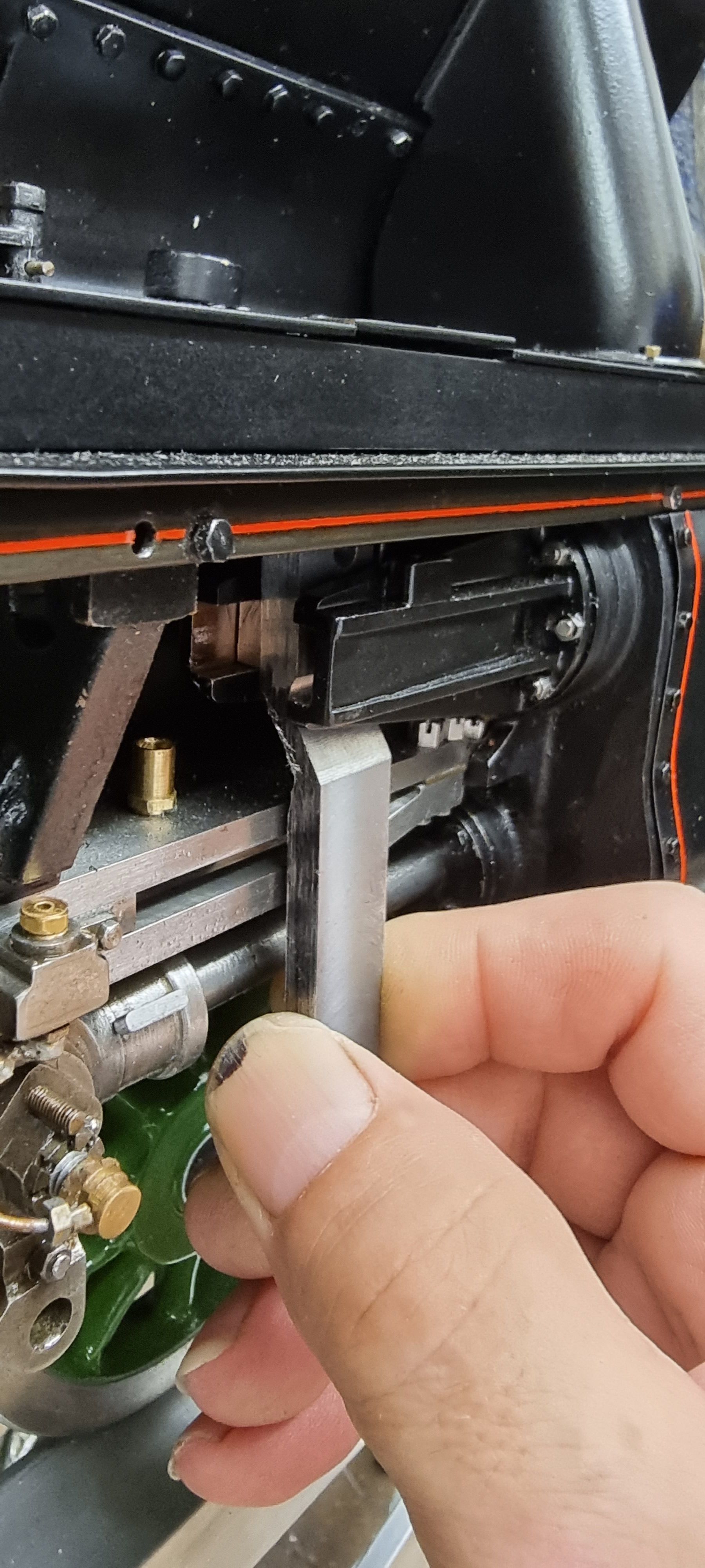
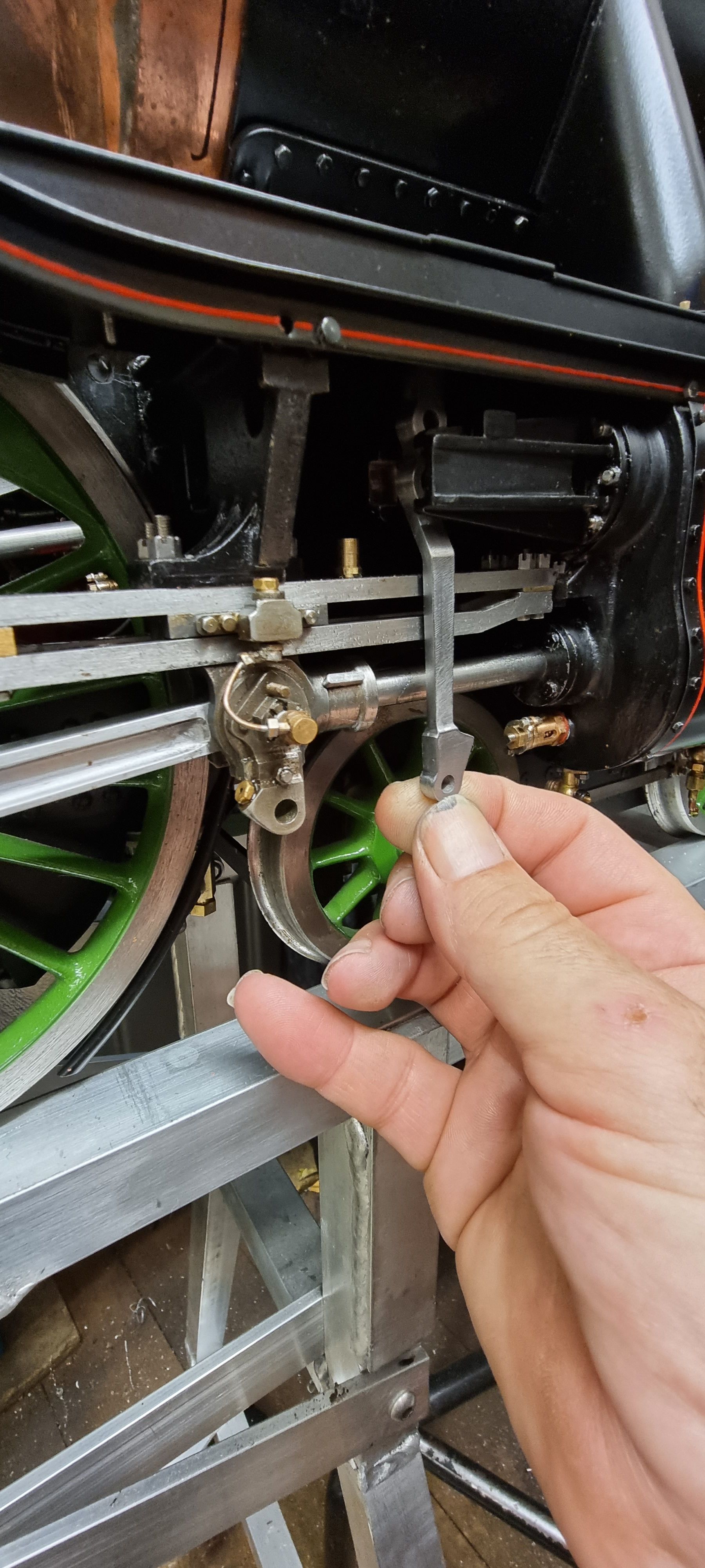
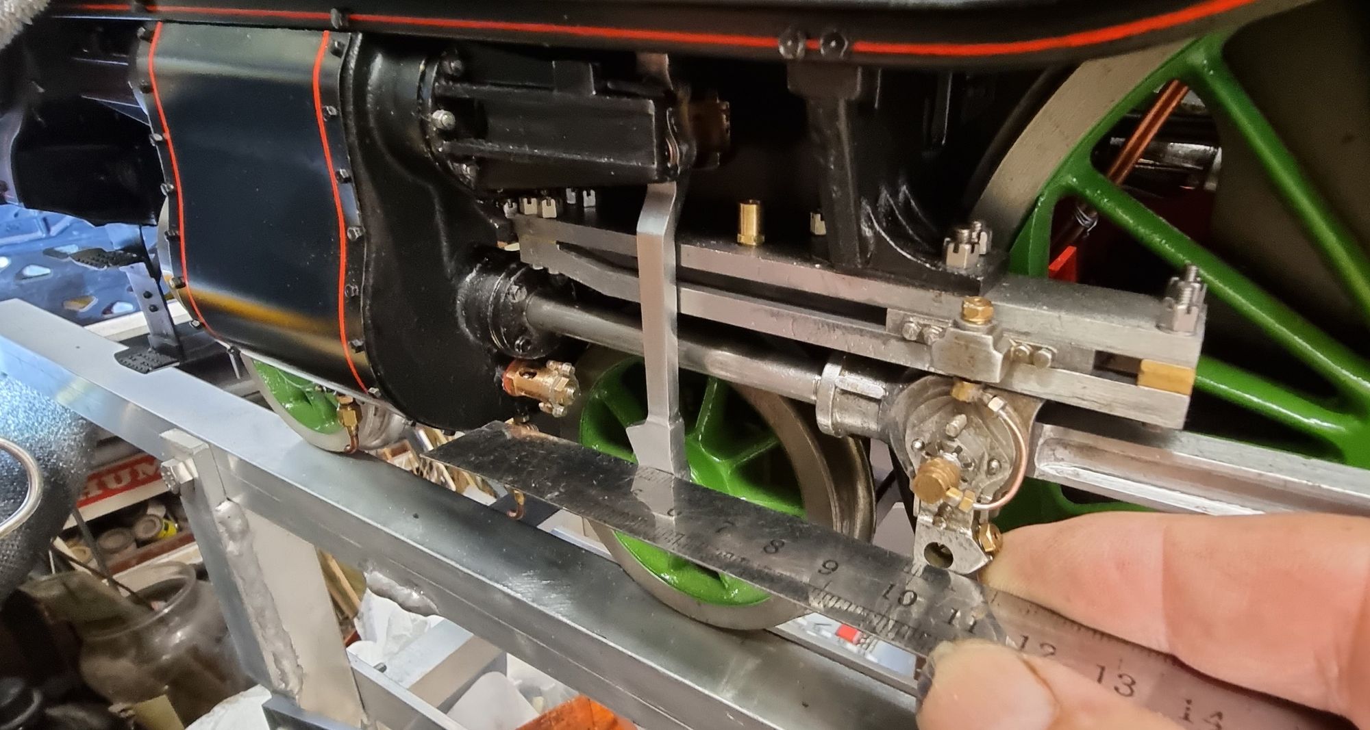
Last picture shows that all seems to have gone to plan. When I machined the 1/32 shoulder to the bush I left it a couple of though oversize, this is so that I can get a very good fit in the crosshead with no rocking movement in the lever. In this picture the lever has been wedged into the crosshead a short distance so that I can check its clearance with the slidebar. As can be seen things are as they should be, on final assembly I'll file a very small amount of the top of the shoulder so that the lever swings freely on its pin. I'll also give both levers a final filing/polish to remove any remaining marks
You can see that I have placed a rule against the drop arm and combination lever to check that they are inline, this check also shows that the lever won't foul against the cylinder relief valve which was something brought to my attention as a possibility by a fellow model engineer and footplate crew.
There's one final job to do which is the oil cups, These have now been made and fitted and the levers are fitted to their respective crossheads. One thing to note here, Don didn't specify which side the stepped bush should fit, or at least I haven't found it? i fitted it to the front but on checking this against the droparm it became obvious that I had this wrong and thus removed each bush and fitted them to the back of each lever. this picture shows the oil pots fitted, note in this picture the stepped bronze bushes are still on the wrong side.
All of the motion parts will receive one last polish on final assembly.