
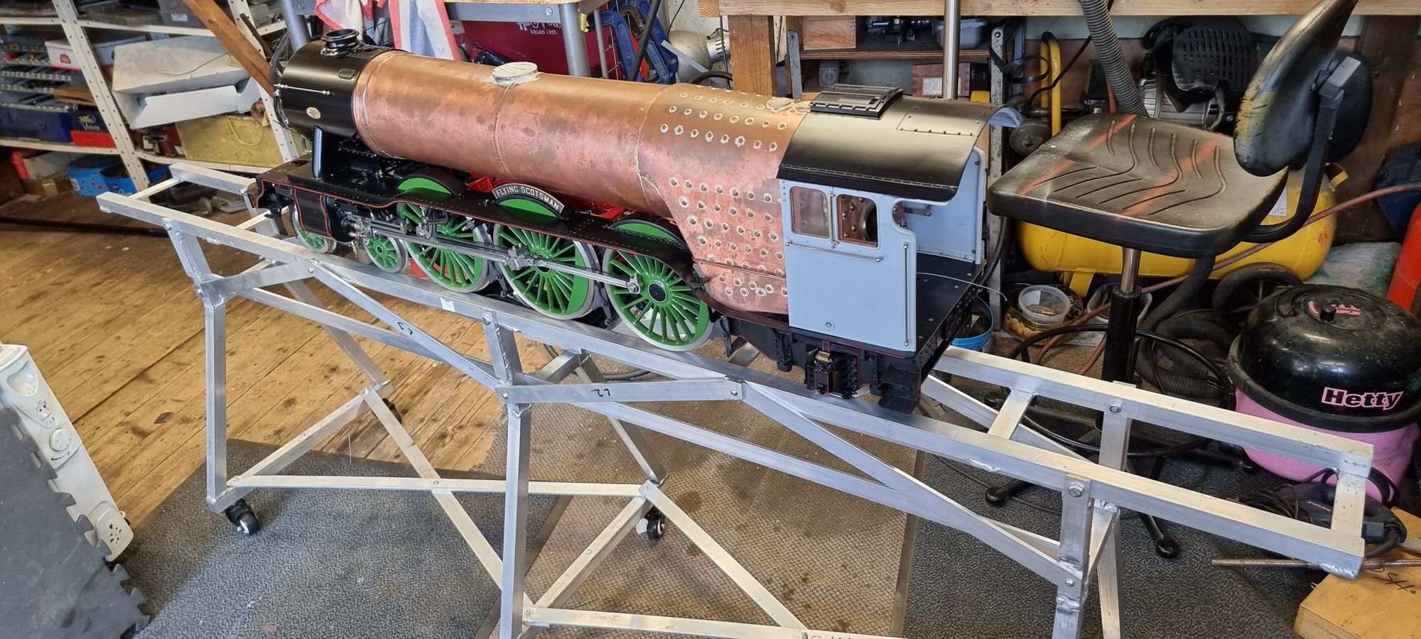
A good working steam locomotive needs to be set up balanced on it’s axles for best tractive effort, something that I have been working on for my model of 4472 in 5" gauge. Before building the weighbridge I studied how locomotives were weighed during the golden era of steam and also spoke to those who have first-hand experience on weighing 4472 ( now 60103) in preservation. The full-size weighbridge design as fitted in Doncaster in 1935 was very clever and intricate, far too involved for our purpose, we can cheat with electronics.
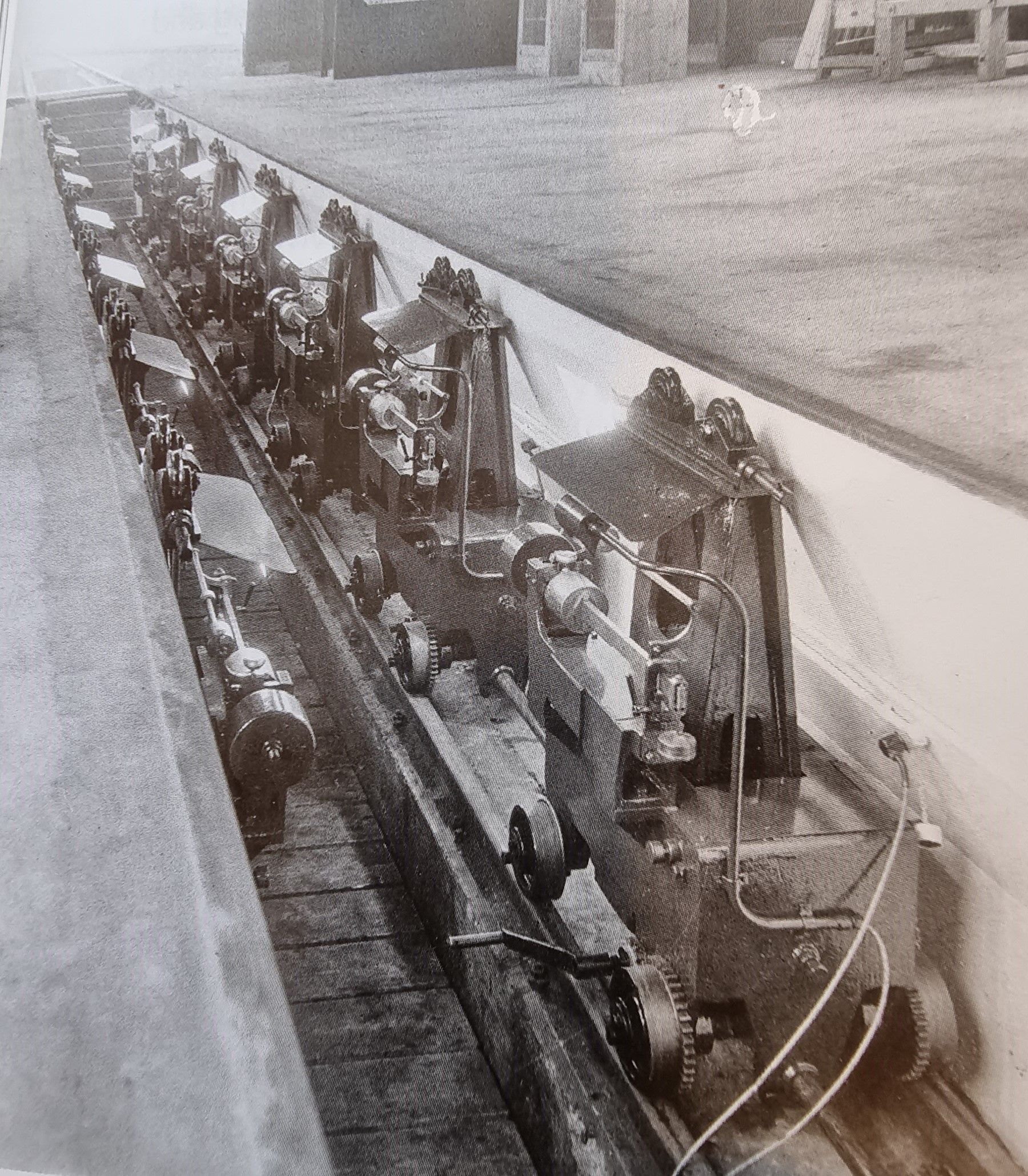
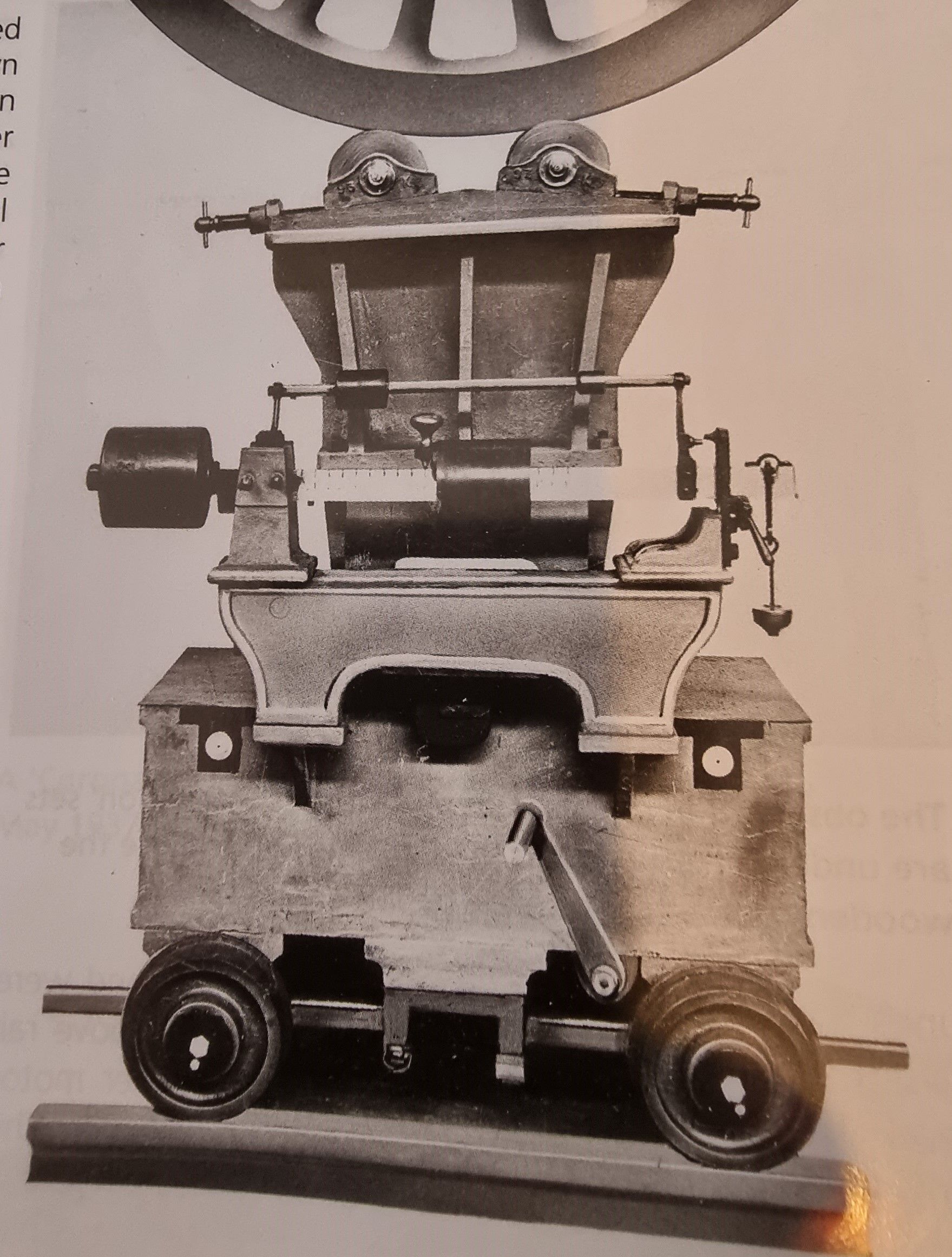
There are a couple of good images in the book LNER Workshops; Development, Expansion and Demise by Peter Tuffrey. The relevant info is in the ‘Doncaster’ chapter pages 87-88, there are two photo’s worth study. One showing the pit with weighing machines in situ and another showing one of the machines in closeup. Peter gives a good description of how a locomotive is eighed and how the weighing machines work using a ‘Steelyard’ system with two two arms (one short, one long) which were out of balance until the weight on the longer arm was brought into balance. The machines could either raise one wheel, both wheels of a given axle and all axles to give an overall weight of the loco. More details can be found in this excellent book.
These are the images, copyright to the above
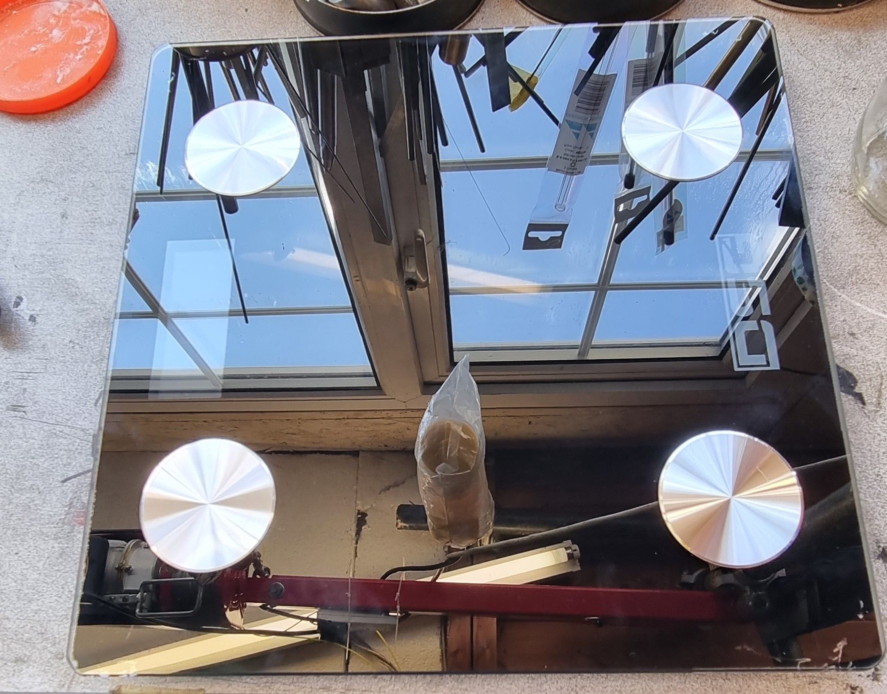
Now we don’t need all of this for our models and the simpler the better works best for me. A cheap set of ordinary bathroom scales will do the job electronically for us, I recommend using a set that has the Bluetooth ability as it makes reading and logging the results much easier.
You don’t need to spend a fortune, I bought my set off eBay for £15, I have seen the same set both cheaper and dearer. The reason that I chose this set is for two main reasons, first I could see in the photo’s that the sensors were only clipped in, second was that the electronic frame was only held onto the glass base by self adhesive pads. Both of these make life much easier when disassembling the scales.
Here is the set of scales that I have used.
The first job was to remove the glass shelf from the electronics, this was simple to do using a metal rule and sliding it flat between the two parts.
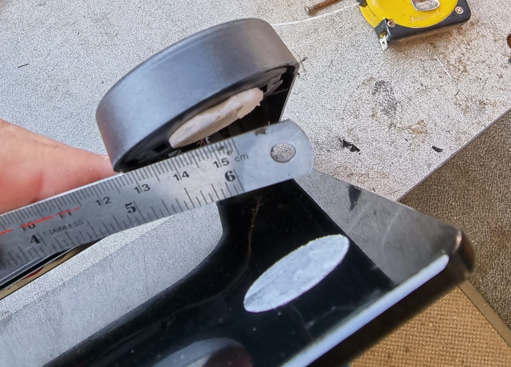
With the glass removed we can see what we are up against.
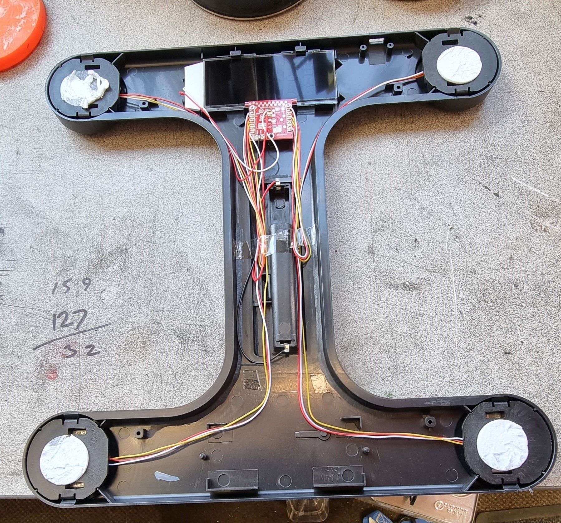
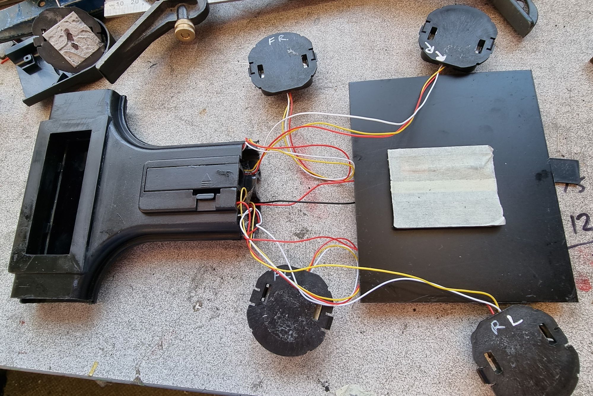
Removing the sensors was very easy, just unclip them from the frame.
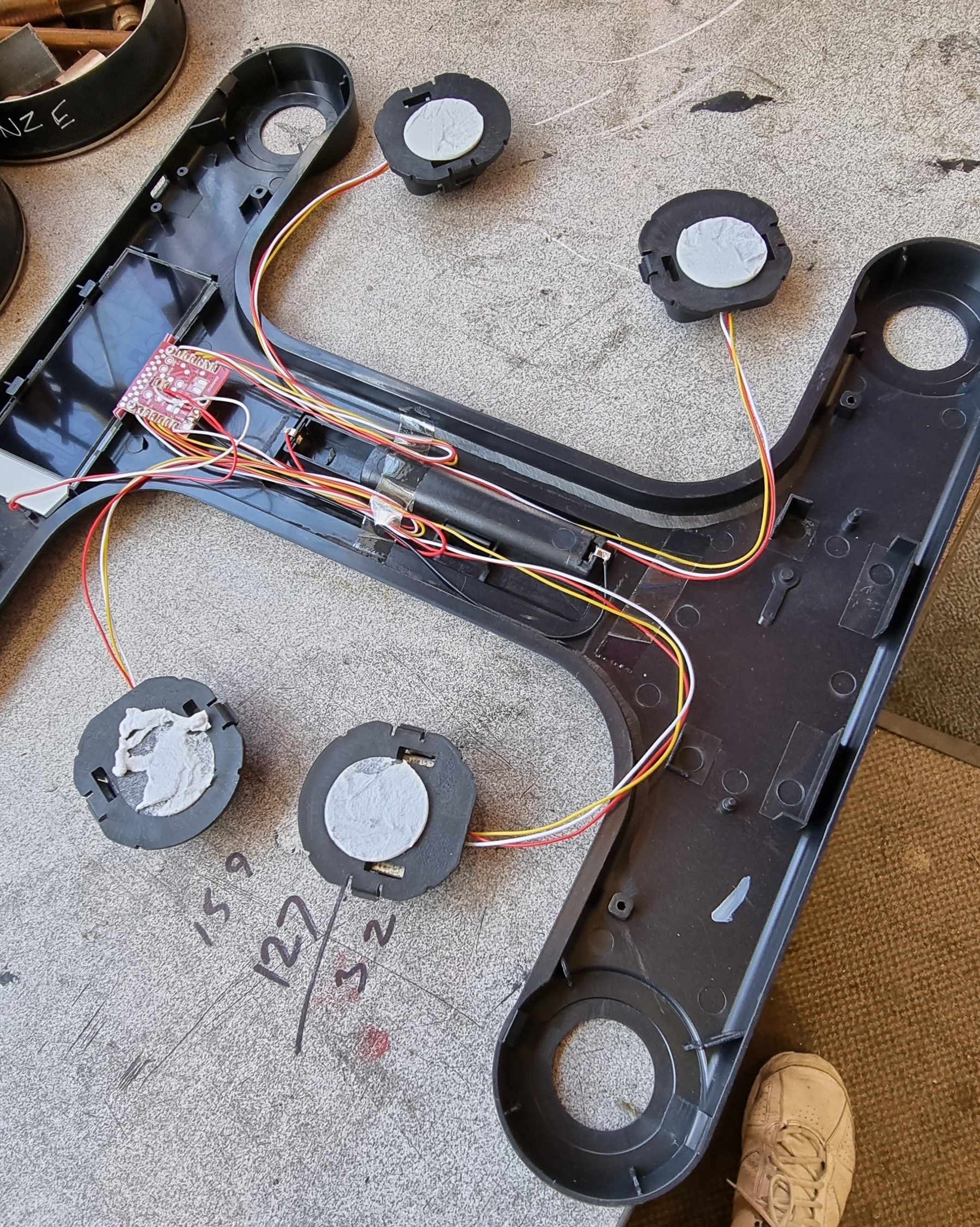
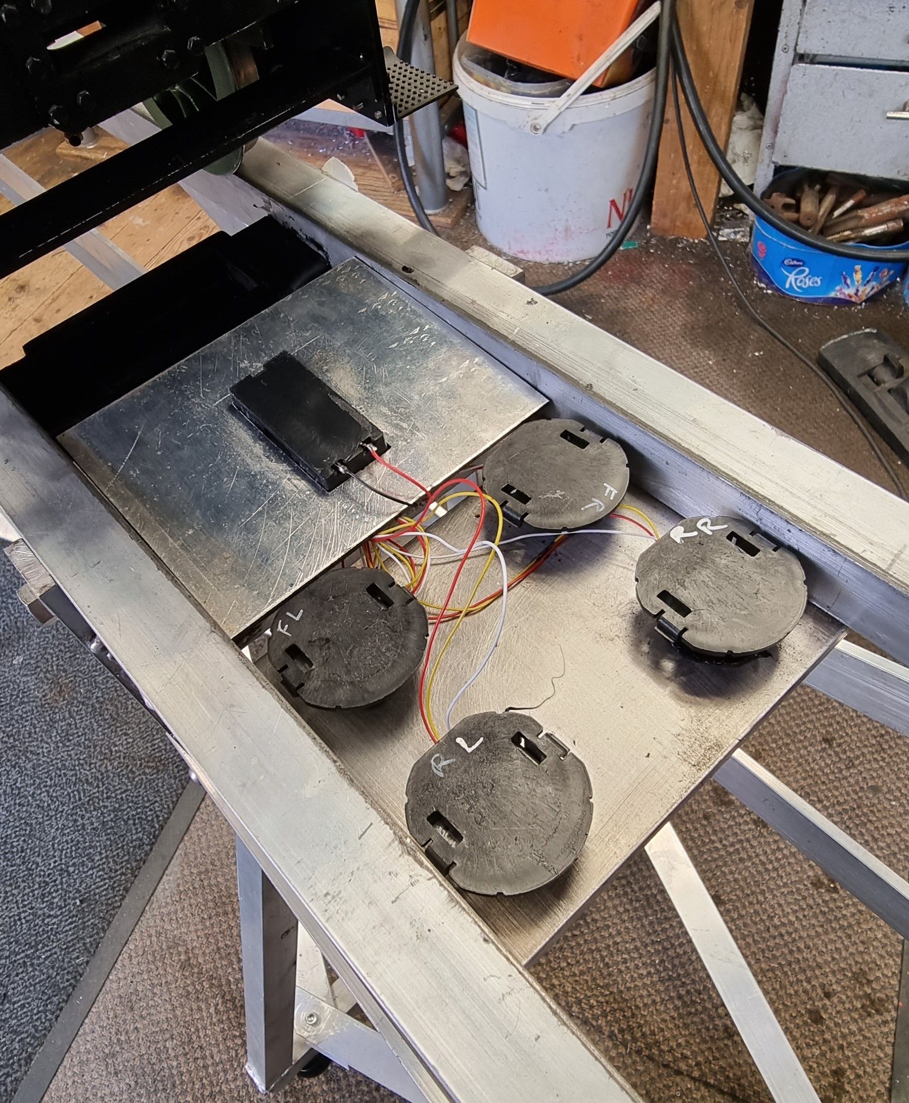
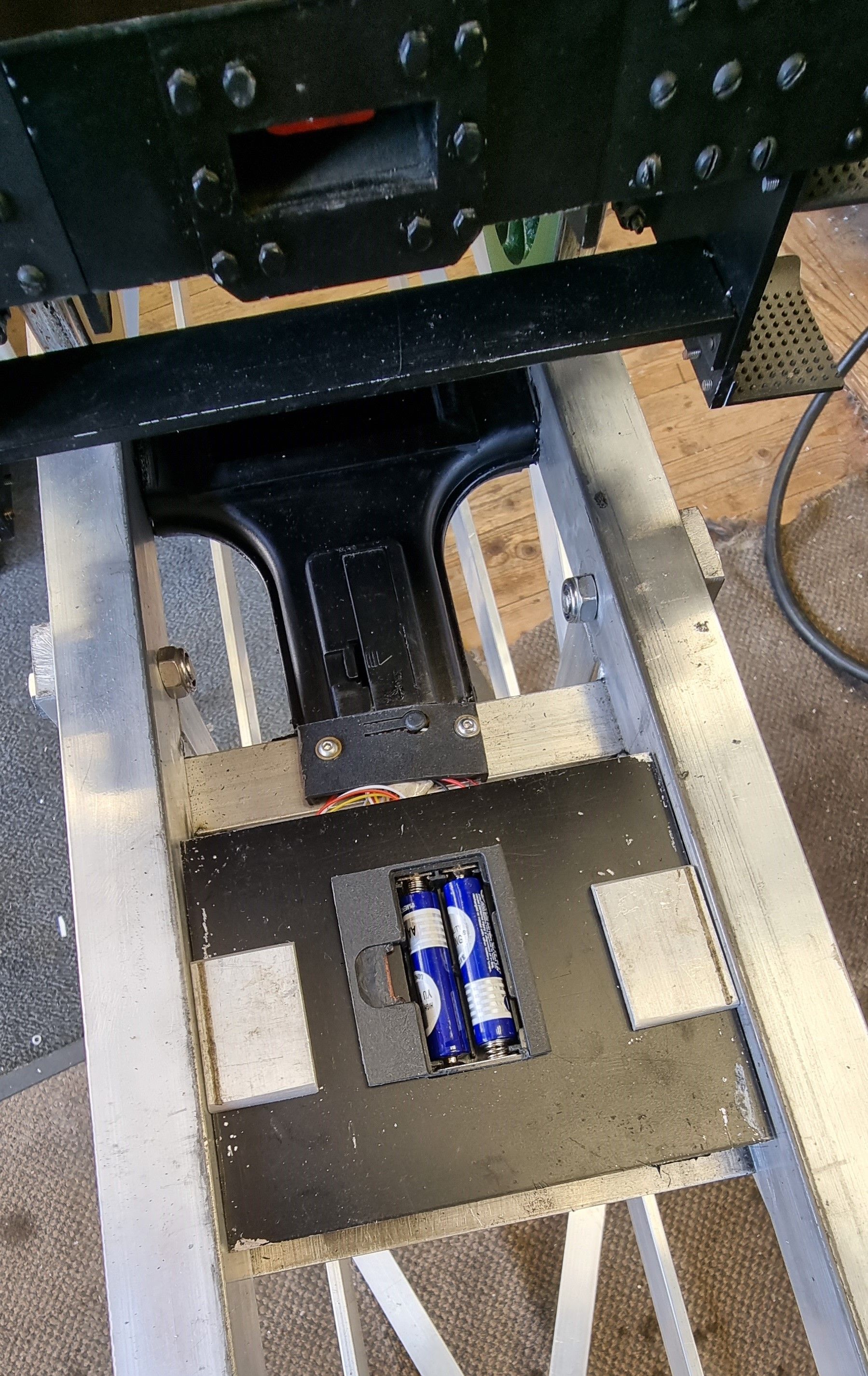
I then went about making use of the frame to construct a housing to protect the electronics and also that would fir between the rails of the loco stand. As can be seen I have cut the plastic frame in half and trimmed the sides for it to fit on the stand. I have also kept the sensors in the same orientation as set out in the scales, I have no idea if this matters but thought it good practice. I cut up some plastic right angle and made a frame around the display panel, I then glued the two halves together using a black silicone adhesive. For the weighing plate itself I have used a sheet of alloy and cut out the centre for a battery pack to fit. for anyone following my lead, when choosing a suitable weighing plate bear in mind that it needs to sit low enough in your loco stand so that without there being any lifting plates fitted the wheel flanges don't touch it when passing. You need this to be able to weigh individual wheels rather than the complete axle.
It was then time to fit the weighbridge to the loco stand, I have used the same silicone adhesive to fit the housing and the sensors to a thick alloy plate bolted to the middle of the stand, the housing also has two screws holding it to a cross brace. The stand is 7 foot long to be able to weigh all 6 axles easily. With the sensors already glued to the alloy the last job here was to fit the weighing plate. The weighing plate in this photo is upside-down awaiting adhesive to be applied and secure it to the sensors. Be sure that the plate isn't fouling the rails either side or it may give a false reading during weighing.
Here we have the completed weighbridge which has already been used as clearly seen by the marks left from the wheel flanges as they have rolled onto the lifting plates.
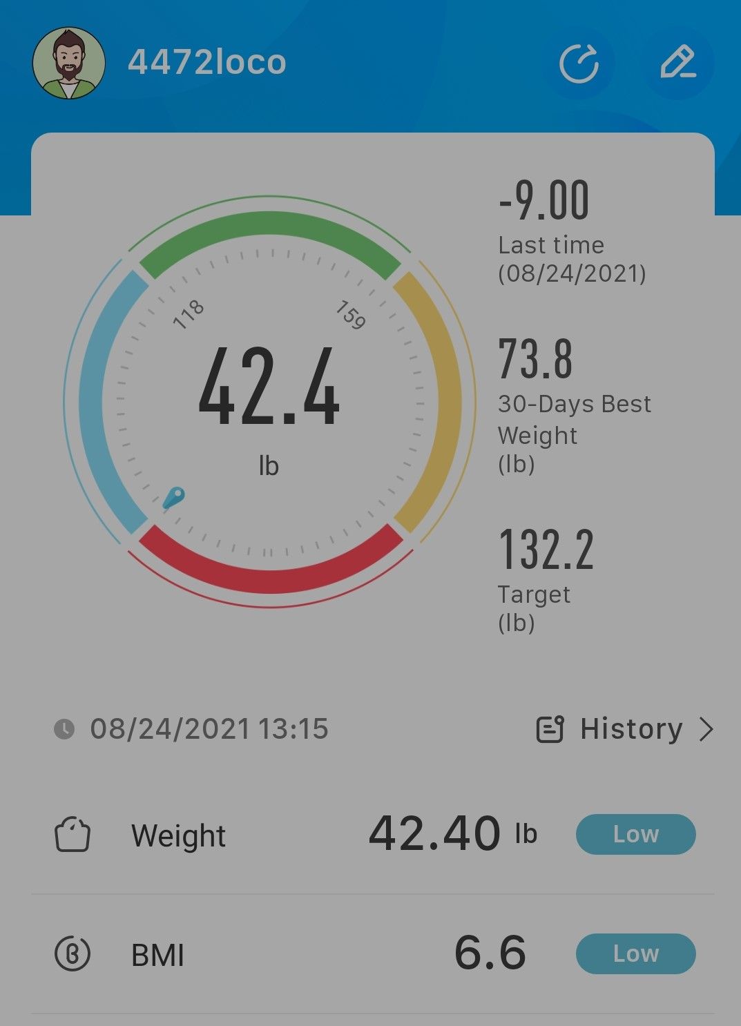
To operate it couldn't be simpler, using the mobile app for the scales I press the weigh tab and roll the chassis onto it's first axle, the app scree will show that it's measuring and very quickly give you a weight, I note the weight and then roll off the scale, press the weighing tab again and roll the next axle on and so on until all 6 have been measured. The picture shows the app for my scales, this is the 'OKOK' app for those wishing to find the same bathroom scales. This particular reading is for the trailing axle and i have set the app to read in pounds, you can also measure in KG if so desired. We only need the main weight, the rest is of no use to us. If possible at some time in the future I may see if I can persuade my son to look at writing an app more suitable for our needs, that is giving data for each axle, toatl loco weight and storing it for future use. I would very much like to do this, we shall see if it's possible.
Now to the model and how to weigh/adjust the spring weight and also decided on what the weights should be.
Adjusting is simple, you tighten a spring hanger to increase weight and lossen to reduce weight, armed with this information i set about getting the axles even.
After some R&D i found the easiest way was for a angled ring spanner to hold the hanger and a box spanner with cross bar for the adjusting the nut below. The picture shows the fun and games that i had getting access to the parts, this picture is an earlier one before I found the quickest way and i must thank my good lady for all of her help and dealing with me during this exercise..
Try to get the axle as close to the centre of the lifting plates as possible, the readings will vary slightly if off centre, perhaps doing a few runs and taking the average is the best solution, IIRC even in full size they have to play around with getting a reading and even then it's out once it's travelled a hundred yards down the track. Here the main driver is sitting on the weighbridge lifting plates.
Luckily during my research of 4472 I came across the axle weights as designed and later changed to during service, for some reason Gresley originally had the main drivers set differently with 24 tons for the leading driver and 20 tons for the other two. I doubt that this ever happened as 24 tons is over the loading gauge and so this was later evened out at 20 tons for each driver on the A1, the later A3's were 22 tons, I'll of course be following the former.
Having the prototype's axle weights from one of my reference books, I could then scaled against the model's total weight and thus work out what i needed using the known axle % rates.
Prototype weights are engine 92 tons, Front bogie 17 ton, Leading driver 20 tons, main driver 20 tons, rear driver 20 tons, trailing axle 15 tons with the percentage split being , 18.5%, 21.7%, 21.7%, 21.7% and 16.3% respectively.
Using the above percentage splits and a little maths I can get a ballpark figure for the model weight (which as of today) is total of 244 lbs (more than I had thought, this makes the boiler alone over 90lbs empty, IIRC the volume is 9 Ltrs full, so nearly 20 lbs with perhaps 15-16 lbs running weight still to add )
Figures of the axle weights for the model today are: (this will of course increase as the build continues.)
Front bogie leading-axle 24.8 lbs
Front bogie trailing axle 26.4 lbs
Leading driver 49.6 lbs
Main driver 49.6 lbs
Rear driver 51.2 lbs
Trailing axle 42.4 lbs
Total weight coming in at 244 lbs.
Taking the figures above which are pretty good after some fine adjusting earlier today, what I need to find with the current total weight of 244lbs is a close match to the prototype axle weights using scaled down figures of the prototypes percentages given above.
The target figures to match a scaled version of the prototype are
Front Bogie (both axles) 45.14
Leading driver 52.94 lbs
Main driver 52.94lbs
Rear driver 52.94lbs
Trailing axle 40.26 lbs
If you compare the above scaled target figures to those of the model from today I am getting very close, very close indeed. There is no need to get the weights spot on now as there's still a lot of weight to be added, but after adjusting the axles today she is rolling so sweetly now, a big improvement from before.
I was asked about weighing just the one wheel of each axle, I did give brief details of how this will be done but have now added this small addition to show this in action. I guess that I hadn't explained myself very well and to be fair I should have included this in the write-up.
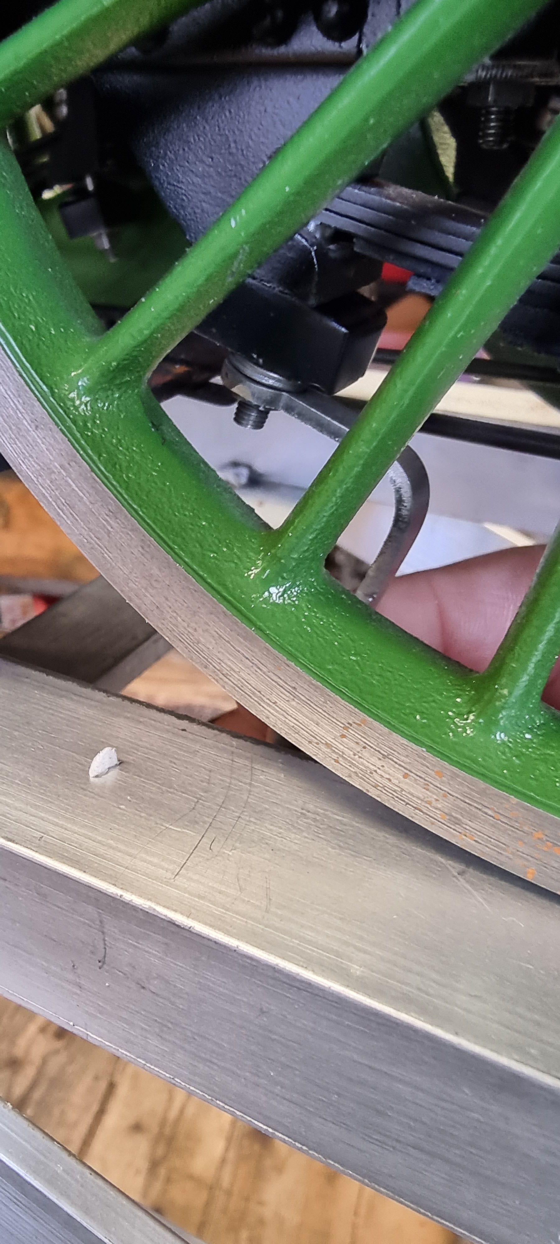
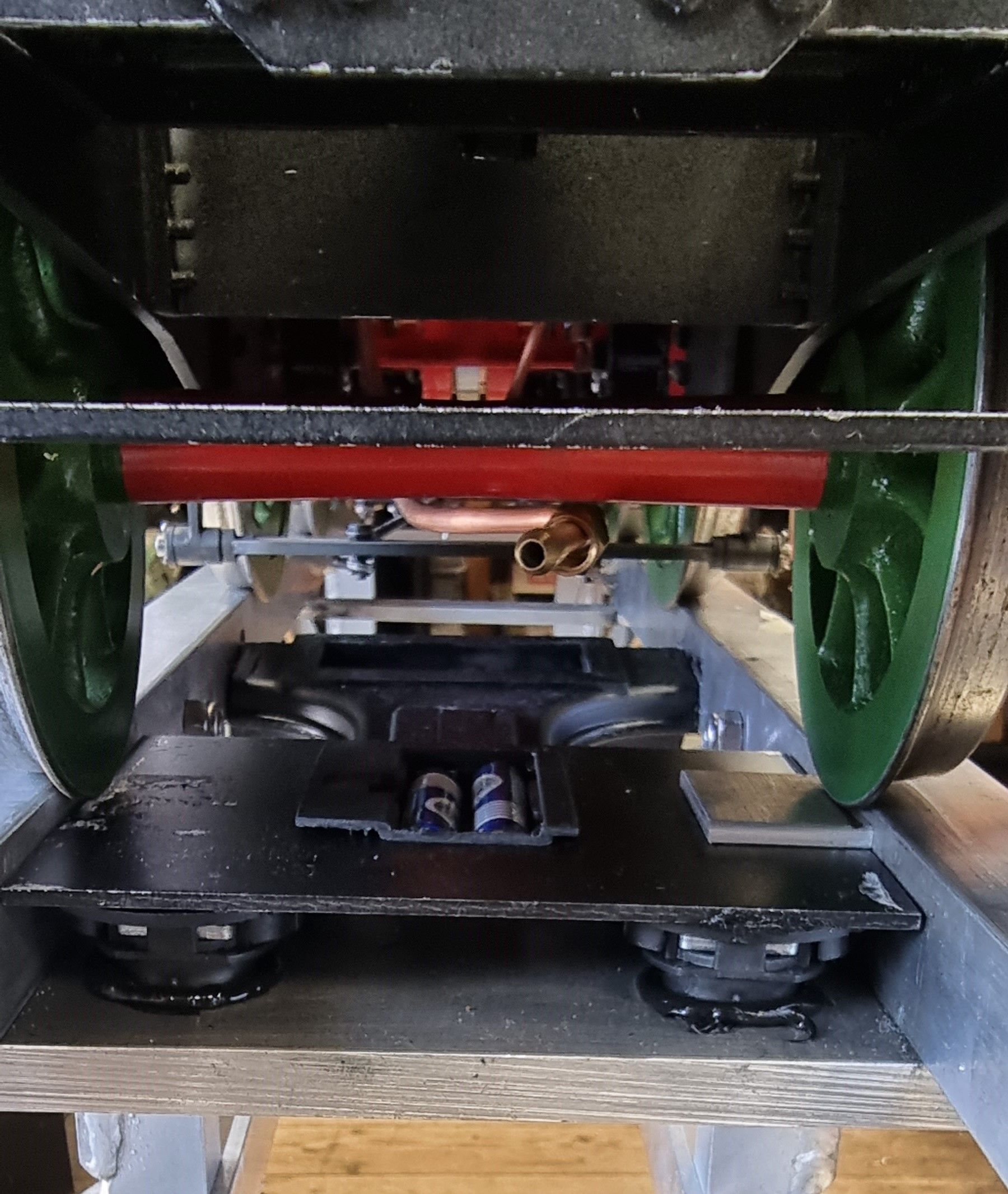
Anyway, to show how this works and how simple it is I removed one of the lifting plates and measured one wheel on the trailing axle, weight recorded was 21.4 lbs which is uncannily close to half the axle of 42.4, just a lucky hit I guess..

Picture to show one wheel being weighed after removing one of the lifting plates, in this case the one on the left has been removed. You can see how only the right hand wheel has been lifted off the rail by its flange resting on the lifting plate.
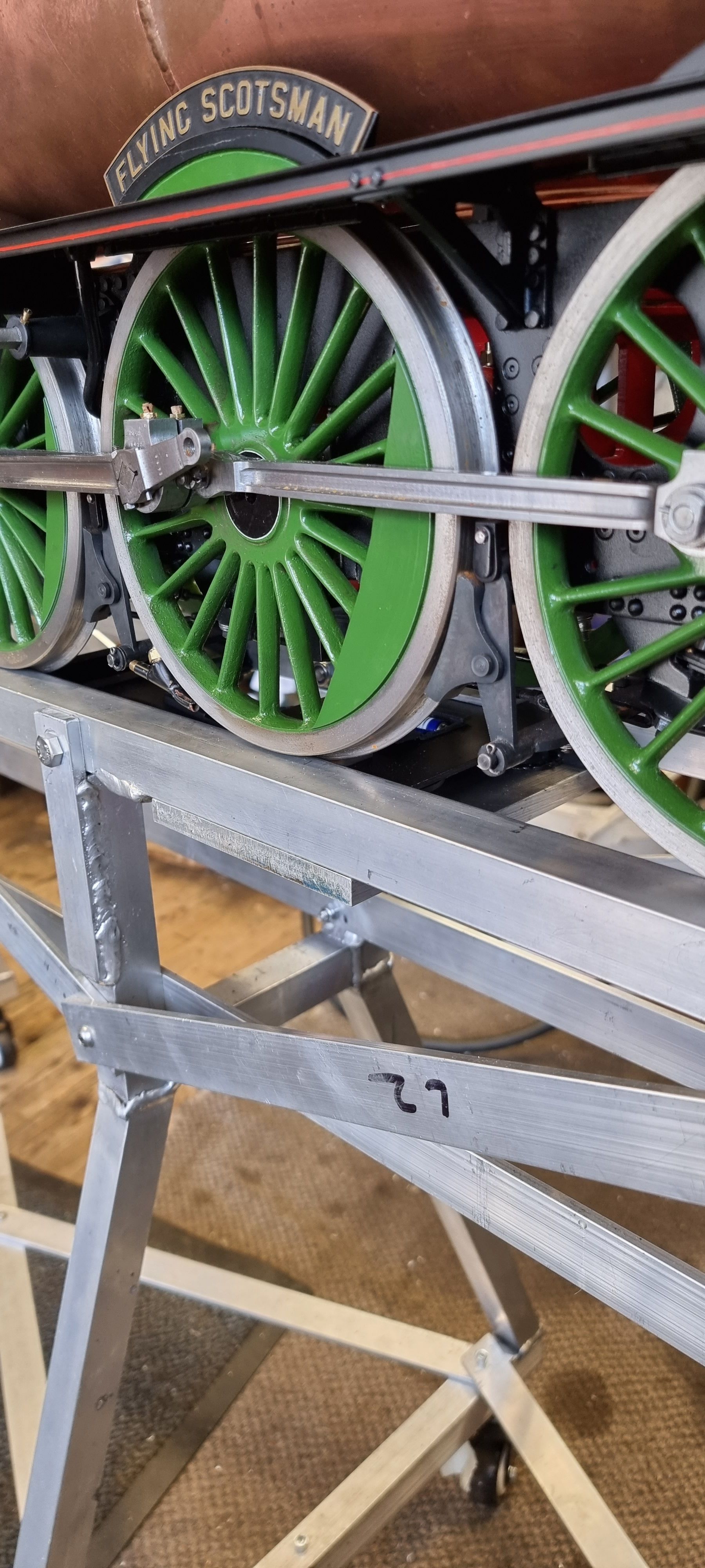
Lastly a picture of the model sitting on her stand/weighbridge
