So where to start?, well I thought I'd start with an easy item, the bogie truck, did I say easy???
I had read Don's "words and music" completely a number of times by now and in fact, many times since, most of which is were a mystery to me at this time but like anything in life it's just a matter of taking it one step at a time and my first step on the engine build itself, was the bogie.
During my research into FS I recorded all of the upgrades during her life so knew that the bogie was one of the mods undertaken during her early career. As built she had the swing link bogie but these proved a problem with reports of the rear bogie wheels making contact with the cylinders causing damage. So Gresley changed all Pacific's for a slide control type between 1931-37 which means my loco will have this type of bogie.
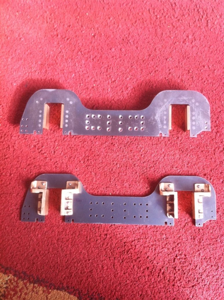
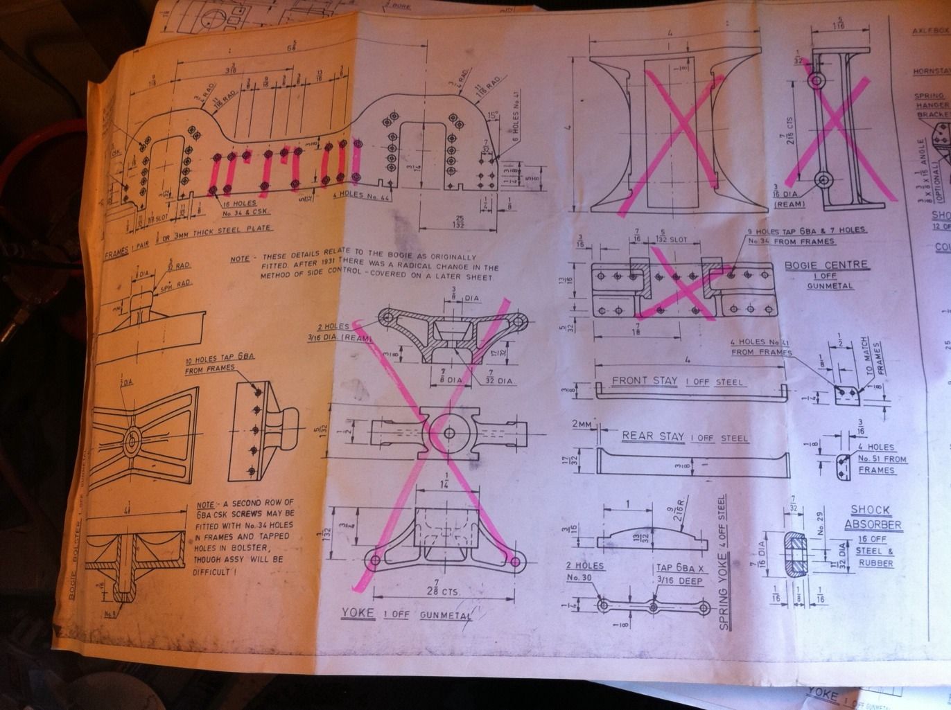
The pink highlighting on the drawing shows the parts of the swing link bogie that will not be needed, the highlighting on the bogie frames is to remind me not to drill those holes as they are for the swing link bogie only, still with me guys?...
Other parts seen here are the same for both types although the bolster requires modifications...
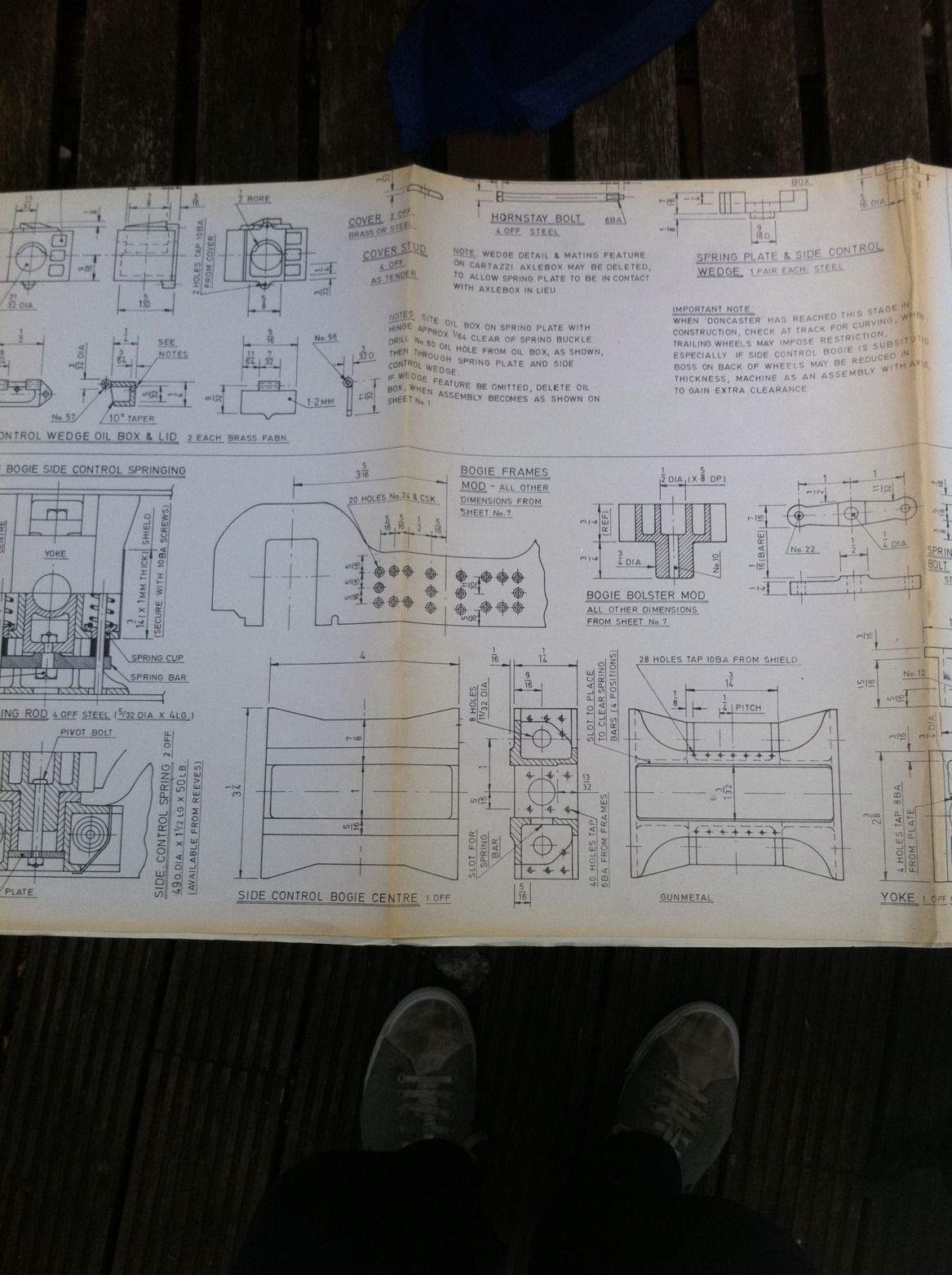
Now this sheet covers the slide control options ( if you haven't guessed yet Don gives drawings for both), the bogie bolster in the previous picture is used for both although it does require modifying . Now the bogie centre shown here is listed by Reeves as the A3 centre, this is not correct and in fact the main reason for me writing these notes. Yes it's the later type bogie but many A1's including mine had this upgrade done years before actually becoming an A3. So for anyone considering building an A1 check to see which bogie they actually had during the era that your building. Another item of course that's different is the yoke, so make sure which ever bogie you decided to build you get the correct castings for it.
I will try to cover all these little differences in an attempt to make things a little easier for anyone else who follows me building this beautiful locomotive .
Bogie frames
I bought these laser cut frames from Steve Harris of Laserframes.co.uk . I have no connection with this company but credit where credit due, the frames are accurate and smoothly cut. Later I'll show the trailing axle frames which were also by Steve, although the first set were incorrect, no big deal, more on this later (much later) when I cover the trailing axle frame fabrication.
Forgive me if I'm teaching some here how to suck eggs ( there's some very talented/knowledgeable folk out there, far more so than myself) but thought it best to give as much detail as possible in how I do things in the hope that it may help others.
So first job was to mark them out ( I didn't have a full DRO on my mill at this stage hence doing it the old fashioned way), on looking at the drawings it became obvious that a good datum to use was a line 1" up from the bottom of the frame, on this line were all of the top holes for the bogie centre stay but more importantly one of the horn holes was on this line too, all holes where measured from this line. Don states to transfer the holes from the horns to the frames so by having one of these holes on the datum and with the horn held square once machined by the slot, this seemed my best option of obtaining an accurate bogie assembly.
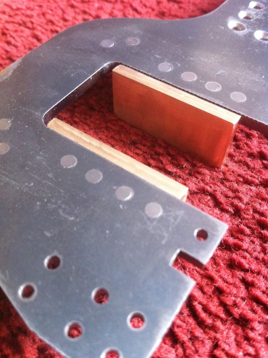
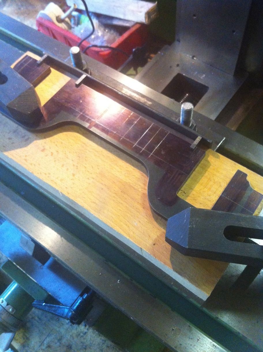
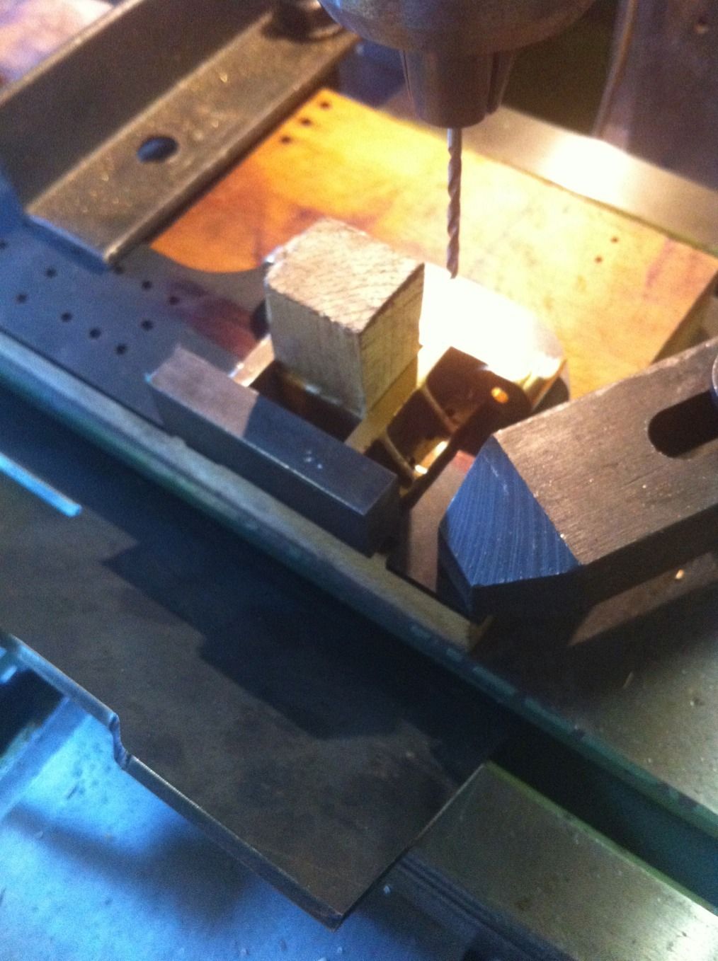
First to get the frames bolted together, I decided to use the four horn stay holes to do this but needed to keep the frames in line first, this I did by cutting some pieces of steel of the correct thickness to fit in the stay slots and then lining these up against a steel right angle that had already been set square with a DTI.
Picture shows this setup , I used a machined piece of English Oak to clamp the frames to for drilling.
After bolting the frames together they were turned around reset with DTI and clamped down. All holes were first drilled using a centre drill and followed with the correct size drill, the bogie centre holes are No.34/CSK, rear stay holes are No.51/CSK, front stay are plain No.41 holes as are the 4 guard iron holes. The frames were then turned over for the other side to be countersunk. BTW the horn-stay holes were No.44 and were tapped later.
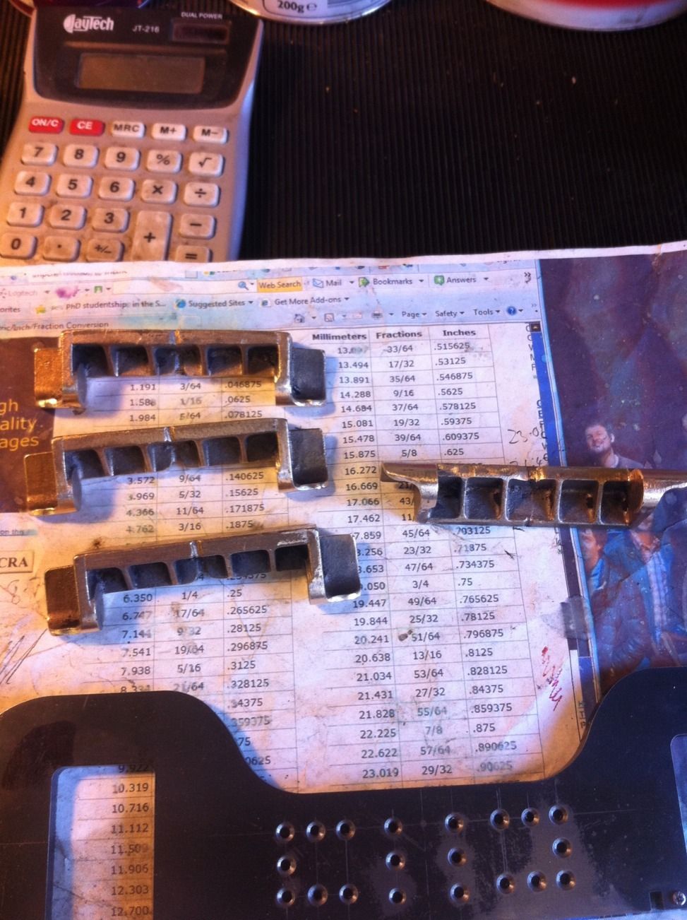
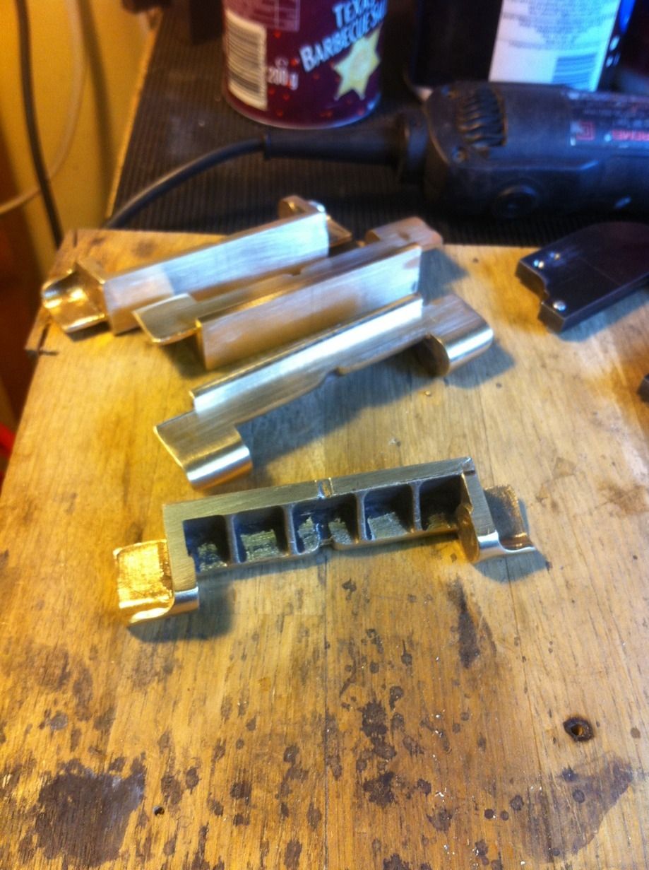
The bogie horns supplied in sticks of two are seen here before machining, I think Don would turn in his grave is he could see how bad these castings were, one of them is actually nearly double the thickness of the others and another has a crack in it but luckily not in a critical place, so what Don describes as an item that requires little machining has taken me three days to sort out and not finished yet..lol
NB: there will be a number of times as we progress where I have issues with the quality of the castings, I'll cover those as i get to them.
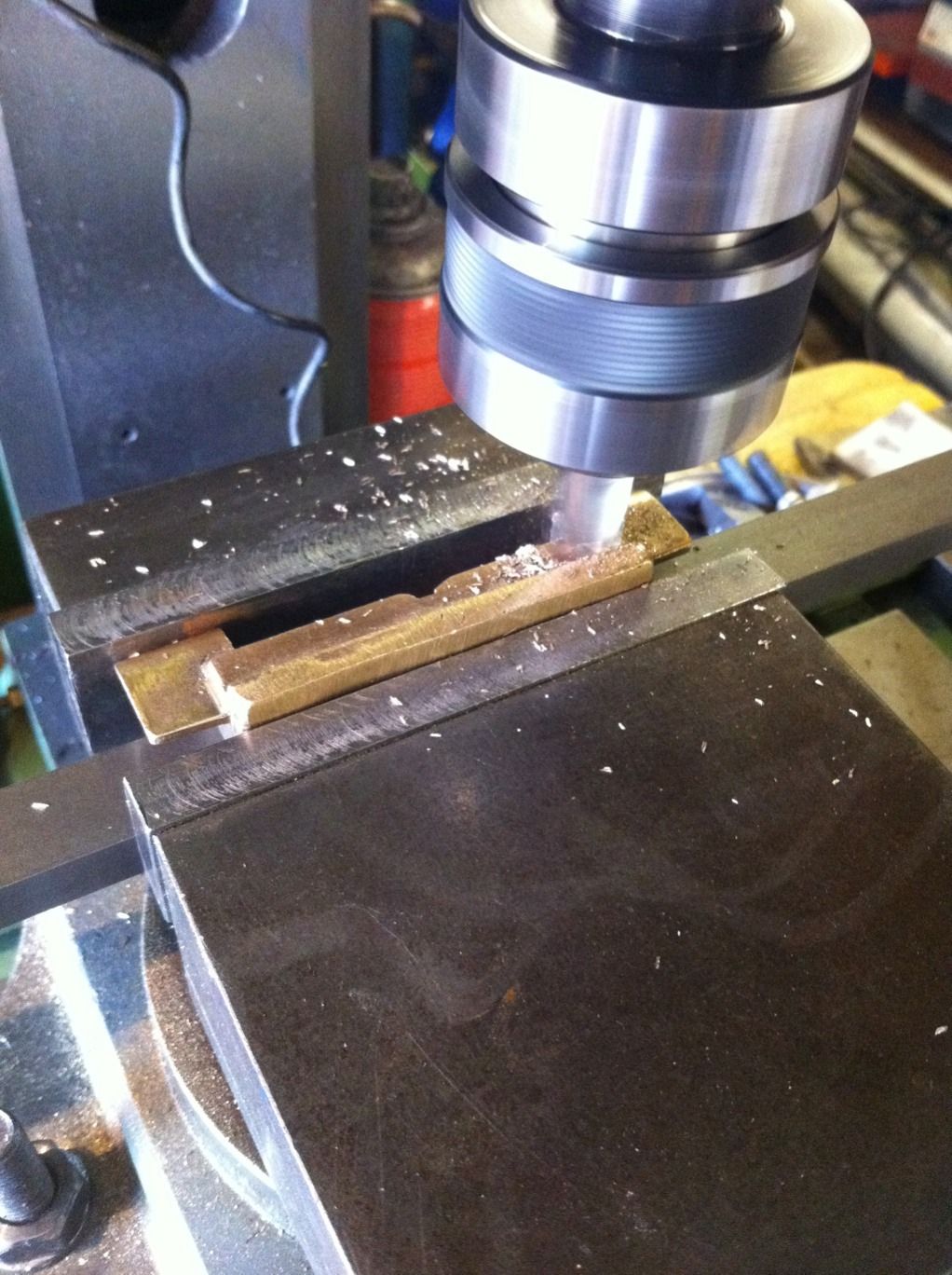
There's two many changes to setup involved to list them all here but this picture shows the face that sits on the frame being machined. I had to take a small cut just to get a flat face and then went from there, once this and the opposite face had been machined ( 1/2" between them) I could then machine the face that fits into the axle box slot, this I have left 10 thou oversize for machining later when the horns were fitted to the frames
All horns now machined, before parting them I marked out the holes. These needed a lot of filing to get to this stage especially the one that was twice the size around the curved section, all this extra work took a fair bit of time.
Finishing bogie horns and fitting to frames
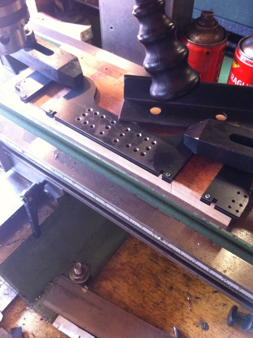
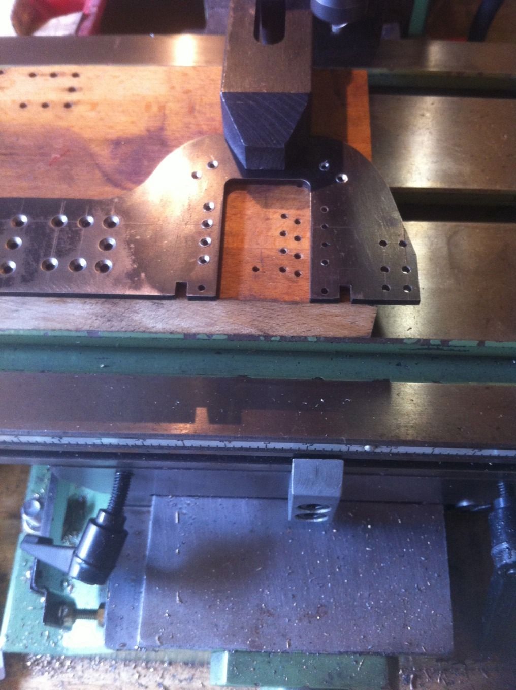
Before getting to this picture all holes were measured/drilled and the horn sticks were split into two and machined to size. I then squarely clamped each frame in turn to the mill bed ready for drilling the horn holes. I lined up the hole that sits on the datum and checked all was ok. I then cut a piece of timber to a tight fit between the horns and wedged it in place, I also used a suitable piece of steel to keep all horns at the same height by pushing it hard against another piece( this time the discarded trailing frame that was incorrectly cut ( and replaced by one of my own drawing later) sitting in the bed T slot. All this was just me being overly careful to ensure all stayed square while drilling the horn holes into the frames. I found it easier and more accurate ( than using a transfer punch) to use the horns as guides to ensure each hole was were it's supposed to be, well it worked for me..
With the horn holes drilled next job was to turn the frames over and countersink them ready for the 5/64 rivets.
Here's the end result, the riveting was done the normal way of holding a suitable snap head in the vice, rivet placed in hole, cut to length and then using a flat hammer to flatten the rivets end into the countersunk. I did one rivet for each horn first, I then replaced the piece of timber to ensure each horn gripper was tight against the frame slot and then completed the rivets. Final job was to file flat any rivet material left sitting proud of the frame. Picture shows both sides and the last picture is a closeup.