This is a big update, this will be where I leave the tender for now until the final painting session once the loco is ready for the same. There's a lot of parts covered in today's update, plenty of extra detail and lots of painting, some of which I still haven't tidy'd up/finished, I'll tackle any little outstanding issues during the final assembly.
Ok, so back to the model, I mentioned previously that the scoop has been left off for safety reasons, that's fine, back the apparatus that operates it is a very distinct part of the tender coal wall and thus imperative to include.
After researching the water-scoop details and deciding how to make it, I got down to fabricating the parts required.
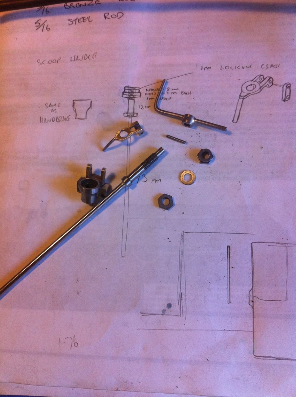
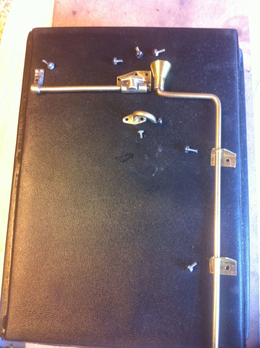
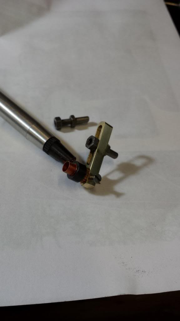
Here I have broken down into component form the various parts that make up the scoop handle. They consist of, spindle,bearing housing that includes the bracket for the locking pin, washer( no PTFE bush needed here) two locking nuts( one with collar) locking pin clasp and finally the handle. So just a few bits to make then..:)
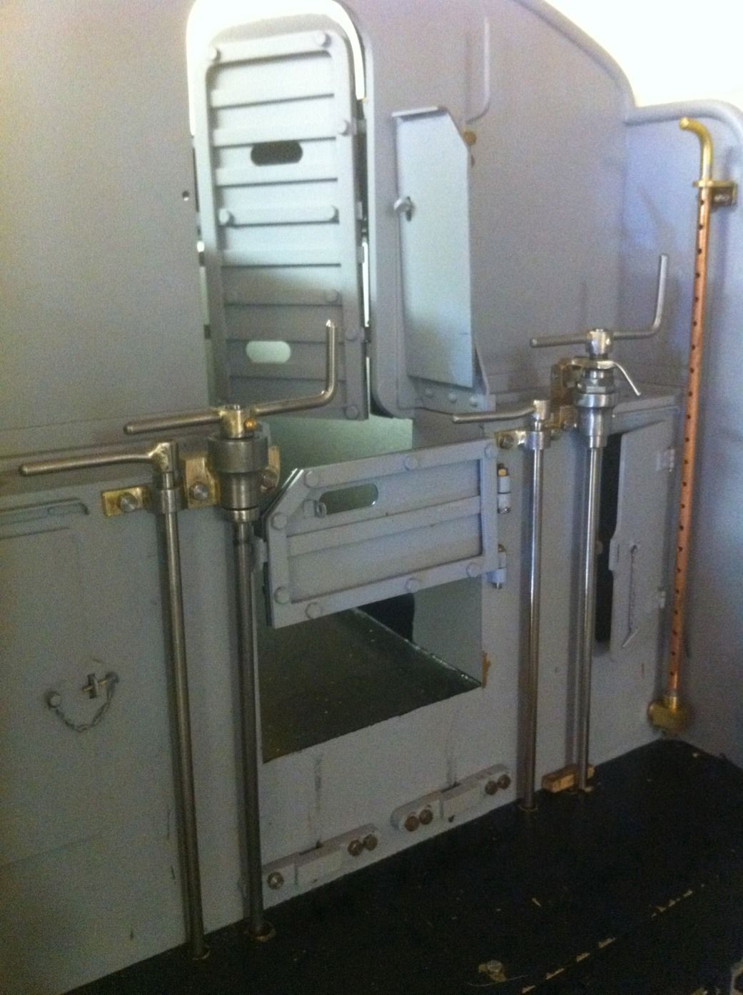
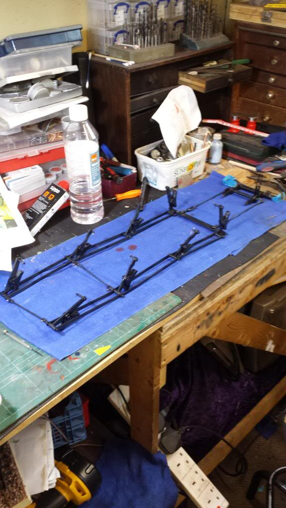
This picture showing the various handles fitted, I still have work to do underneath so haven't refitted the wooden base yet in this picture, this will be the new wooden base with the planking orientated correctly. I seem to have mislaid the details for the water handles, they basically follow the others in construction, they are connected to two 90 degree globe valves below the floor.
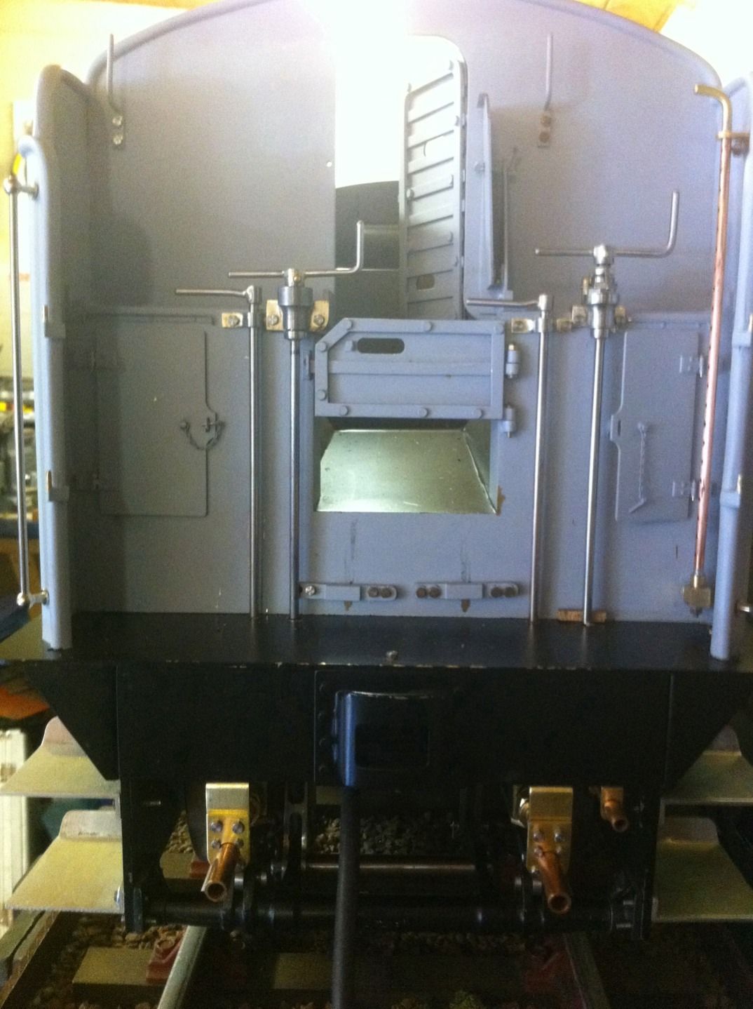
This picture shows it's beginning to get busy around here but still has a way to go. Other parts seen here not mentioned before are the pick iron brackets
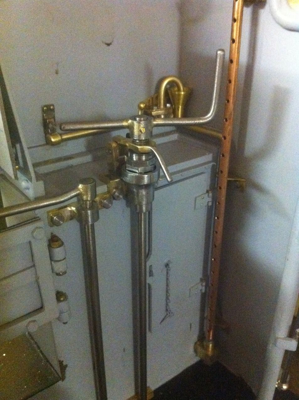
Now for even more extra's, looking at various photos and more useful still the 'Elizabethan' film clip on YouTube I got a good idea of what the various parts do and how they operate when taking on water using the scoop.
I could see in the film that the fireman would drop the scoop by unlocking the clasp turning the handle, wait for water to come up out of a swan neck pipe and then quickly raise the scoop followed by re locking the clasp, at least this is what it looked like to me.
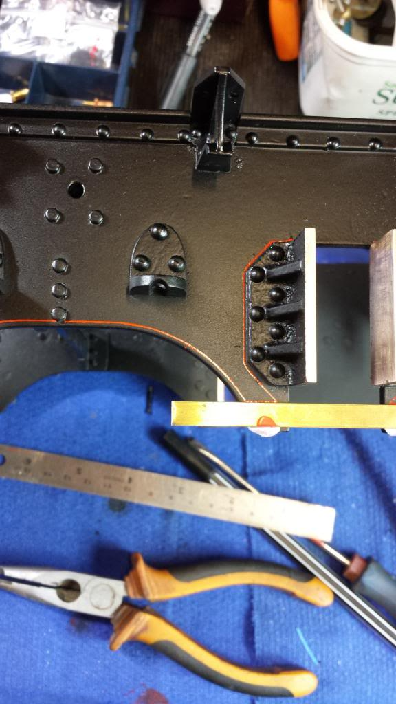
these are the parts that I made, I could see from my research the support plates seemed to vary a lot in shape and size between tenders again just showing how different they could be. I've followed the video here , taking a still so that I could see it a little clearer.
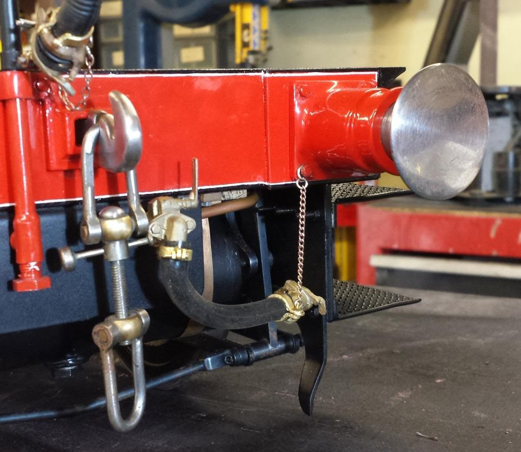
And here we see the parts fitted, it was a bit of a pain to fit( fingers too big again) but I'm happy with it. there were two bolts at this stage that I couldn't in due to the swan neck pipe getting in the way so when everything was apart for painting I fixed dummy heads over the holes.
The corner plate seen in this picture was later changed to a larger version after finding a better photo to judge its size better.
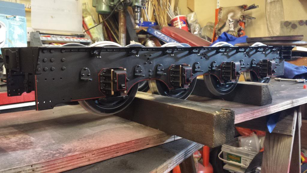
We now get to that stage when it was time to get some proper paint on the chassis and do the lining too. A few things have changed since these bits were done, nothing big, the most noticeable is perhaps the buffer stocks which show as red here, I later changed these to black and also lined them in vermilion.
before I could make a start on painting the chassis I first needed to disassemble the tender as it had been sitting there for two years and was showing some signs of surface rust. I wasn't sure before this stage as to whether I would paint the tender before completing the engine or paint both at the same time. Having now seen the state of the tender with many parts not painted and considering how long it took me to get this far it was clear that I needed to at least finish the chassis completely including paint. The body will be tackled when the model is more or less completed, or at least when the model has raised steam and all 'green' areas are finished.
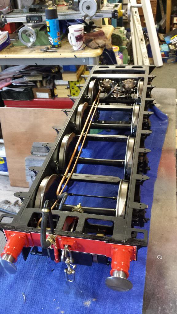
The chassis, minus buffers, steps, braking, including the vacuum cylinders which I had made as a compact quick release item. some of you will have a good idea just how long it took me to completely strip the tender chassis down for painting.
The braking linkage... not having had these off together before I shared this picture purely as a matter of interest.
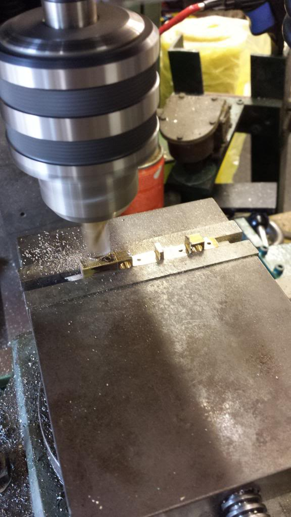
After painting the chassis black and the buffer beam red I put those asaide to harden properly ready for doing the lining. I then moved on to a little machining, to begin with the standpipes have a metal clip that holds them to the buffer beams so I decided to get those out of the way. For such simple things they certainly took a while to do, I started with 1/4 sq brass bar, enough for both brackets (loco too). Marked them out for the hole that the standpipe goes though and the 8 BA mounting holes. I drilled the small mounting holes first, clocked the bar 90 degrees and drilled the holes for the 3/16 pipe. These are not really holes , these are clips however the quickest way to do this in my mind was to drill the hole close to one edge and then saw and file to finish. Before doing the final stage for the large hole I machined off the relevant areas to form the clip as while the holes where unfinished the bar was more solid for the machining process.
This picture shows the last area being machined
Once the machining was finished it was then just a case of separating the two clips and carving to shape with the belt sander and files, final finishing using a sanding sponge.
Here is one of the finished brackets/clips attached to the tender buffer beam to hold the standpipe. the 3/16 hole for the pipe was drilled a fraction under size so that the pipe clips into the bracket and is firmly held in place, the other bracket is on standby for when the loco is ready...

I then took a look at how I was going to tackle the lining for the chassis and decided my best bet was to make an adjustable spacing tool similar to what I remember seeing in Chris Vines book ( how not to paint a locomotive), it didn't take long and means I can now set the pen for lines up to approx 15 mm depth from the edge. It's a simple design that I came up with, some suitable square brass stock, one end I drilled a 2.38 mm hole for the 'Bob Moore' pen's stylus to fit, cross drilled and tapped 8 BA so I can lock the stylus in place and then I machined a 3 mm wide slot 15 mm long for the adjustable pins to fit. I made two pins of different lengths threaded 5 BA with two nuts so that they can be locked in the slot at any position needed.
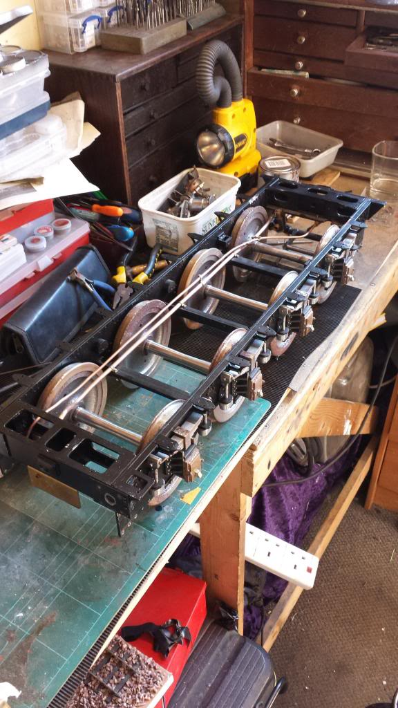
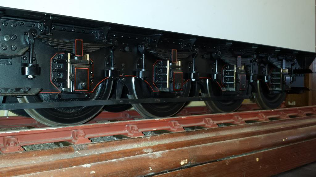
Just to give some idea of what's involved in Doncaster's chassis, there are 280 parts here and that's just for the suspension/axle. It took me 2 days to get these parts ready for painting.
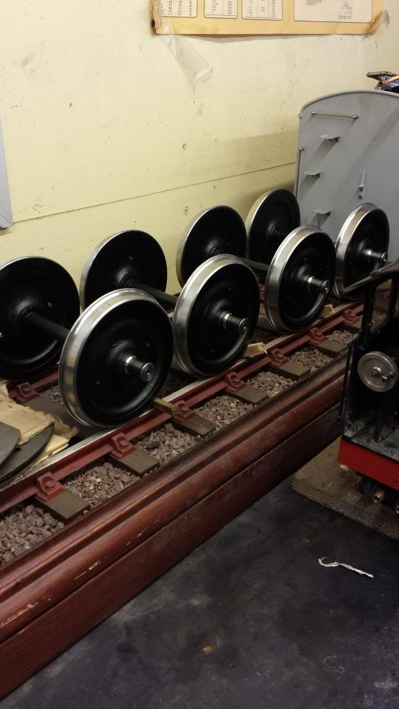
i also put some paint on the wheels which were then ready for refitting, I had been shocked at how much rust had built up on these over the two years of storage, I'm pleasantly surprised at how well they came out.
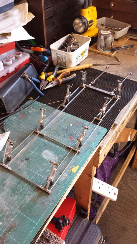
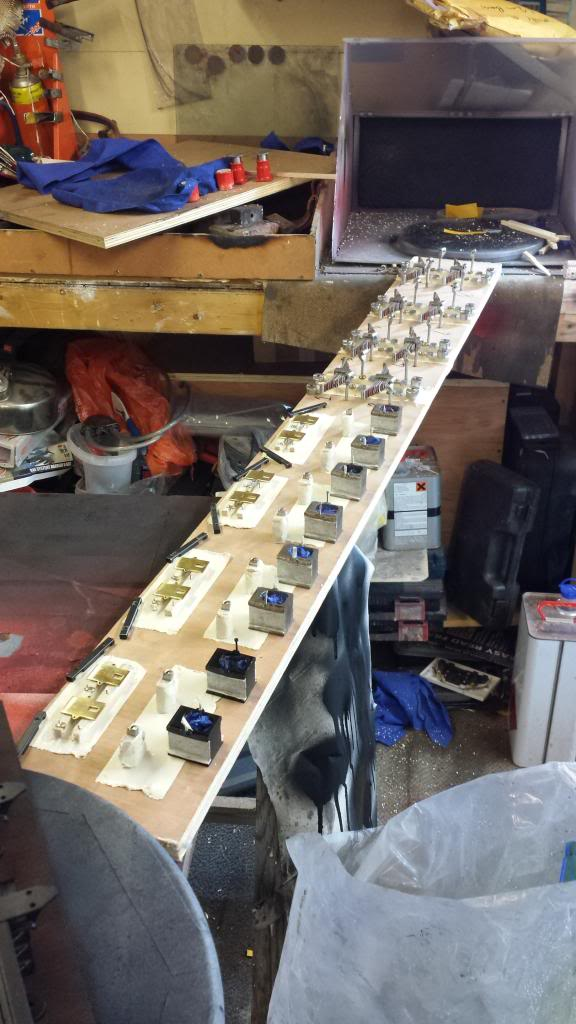
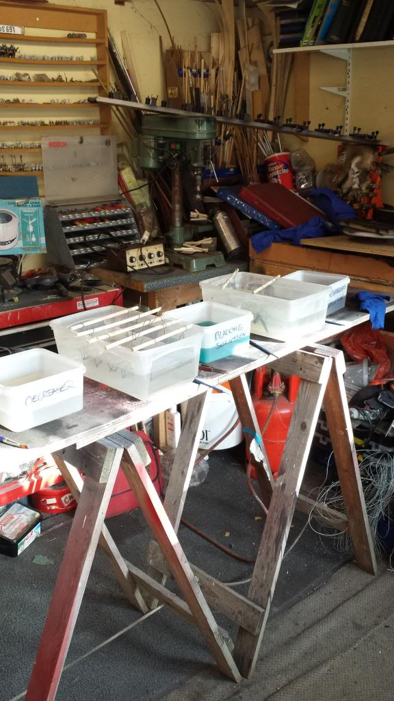
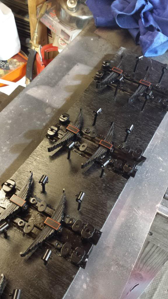
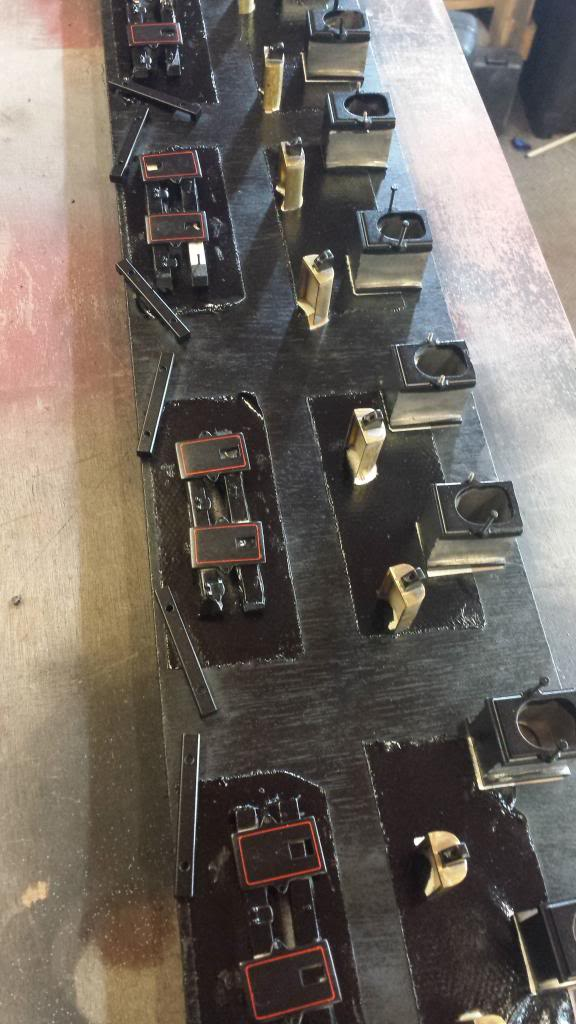
It was then time to consider how i was going to paint the brake gear, I decided that paint may not be the best way as these are close fitting moving parts and so went the 'Chemical Black method. I spent a day getting to grips with chemical blacking and have to say I'm sold, I didn't know what to expect in either finish or durability but so far I'm very impressed. I bought my kit from Frost Restorations after they were recommended to me by my eldest son. The kit includes all you need except gloves and safety glasses, I ordered a set of latex gloves with my order, iirc total price was around £47 (price from ten years ago before this update) which includes 3 x 2 ltr tubs for using the chemicals in. I spent most of the day doing the brake parts as can be seen below which isn't bad considering how many parts they comprise off.
this was my little set up for the process... order of play is left to right, degreaser for 10 mins, rinse in water, dipped in black solution for 4:30 (instructions said not to go over 5 mins), final rinse in water, dipped in dewatering solution for 10 mins and then left to air dry.
What amazed me was that I could handle items immediately after the blacking process without rubbing any off, in fact you have to rub them dry with an absorbent cloth before the dewatering process.
Back to the painting, I had now done the vermilion lining around the spring holders and axlebox covers...to my eye they are not perfect but may not be so prominent when on the model, I will address any parts I'm not happy with on final assembly. Here are the spring holders, for these I used the pen with a guide.
Next were the axlebox covers, these were done again using the pen but this time using a template as the guide
Here I have completed the first stage of lining the vermilion on the chassis... below is a close up showing how the lines can vary at this stage of the process.
What I have learnt though is that after the paint has settled and dried it looks a lot more even, so I leave it till then and use a small brush to sort out any bad parts, also before the paint dries I use a cotton bud or tooth pick soaked in white spirit to remove any unwanted paint.
I still have to do the black outer lining around the buffer beam.. I plan to do that next... then I can start to re-assemble the chassis.. I'll update either later today or tomorrow unless something goes badly wrong...let's hope not..
I decided to put the wheels back on while giving the lining time to dry before doing the final touch ups...Ooo err..to be honest I wanted to see how things were looking although after fitting them I realised that I had forgotten to fit the spring holder plates first so they had to all come off again...lol
Things seen here are beginning to look the part, I was amazed at how long it took me to get the spring gear back on the chassis.
As can be seen in the above picture , buffer beam had now been lined although I had a few area's to touch in once the paint had dried, looking at the photo it was also clear that I hadn't put the right hand buffer back properly.
I refitted the vacuum reservoir tank after checking that it was leak proof , took it to 100 psi with no signs of a leak from the tank or it's fittings. I them etched it, primed and top coated, I decided to leave the holding bands unpainted for no other reason than I like it like that.
NB: might change this later...:)
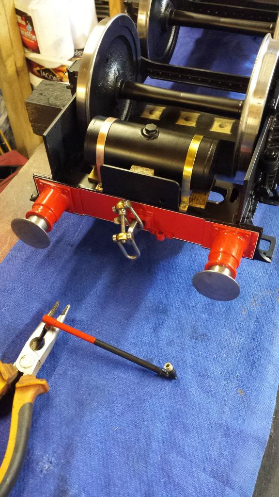
The tank is supported with Oak blocks, two between it and the chassis and one between it and the tank shield. I also turned up the standpipe Tee, silver soldered the parts together and then secured it to the bottom of the pipe, I still had the condensate valve to make which I did over the following few days... The pipe had been painted and was waiting for it to harden before I could fit it to the beam.
On this day it was a productive morning...In this photo we see the vacuum hose assembly so far, there was a small bracket that needed making that secures the pipe to the soleplate, at the time I thought it best to wait until I had the body back on as I had a lot more to do before I could test the brakes.
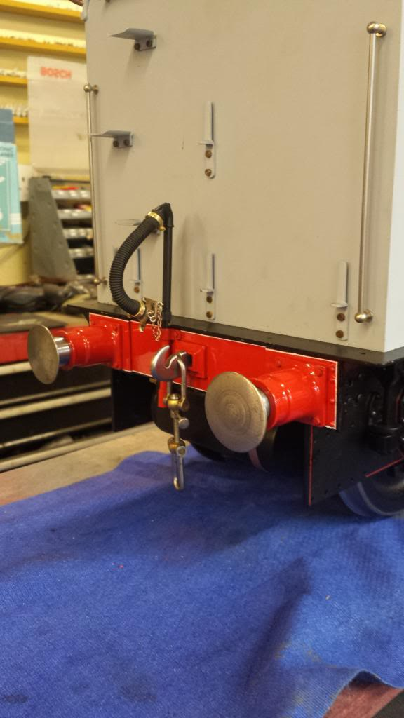
Here I had now rigged all of the brake pipework ready for the vac test.. I sucked on the tubes and could certainly get a vacuum on the main 3/16 pipe by blocking the pipe to the vacuum cylinders, in doing this I was able to check that the Doug Hewson hose was sealing properly which I'm happy to say it was.
here we have the general layout of the braking system..
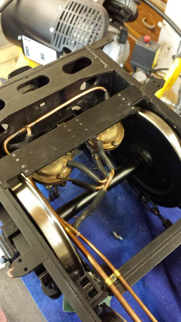
now a close up of the vacuum cylinders...
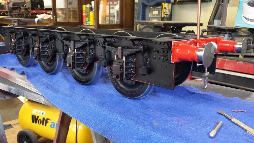
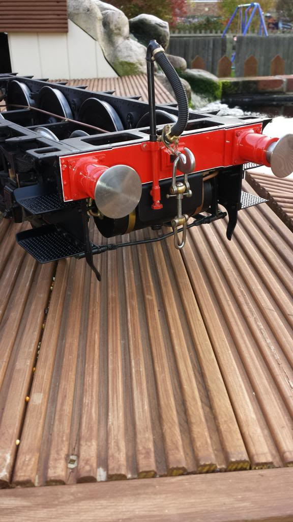
Yet more painting and assembly, steps now finished and refitted to the chassis along with the guard irons. I'm glad that I spent the time on these as they would have looked a bit plain if leaving them without rivets and to me they look so much better, practical and more prototypical.
There are 1238 0.79 mm holes or for those imperialists among us 1/32nd that have been drilled and countersunk in one move using a BS0 centre drill, rivets cut, hammered and finally filed flat.
Moving on to fitting a Doug Hewson heating hose, I've had to fit it a couple of mm lower than is seen in some photo's so that the fixing stud cleared the 8 BA bolts that hold the shield on but I doubt if it's noticeable
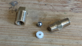
Picture shows the components as to Don's design for the condensate valve, although rather than following Don to the word, I decided to use hex bar so that I had something to tighten up with without marking the paint too much, these parts will be buffer red of course. So instead of using 3/16 and 1/4 round bar I used hex , other than that the parts are made to drawing. The parts consist a PTFE sealing washer and a 3/32 stainless ball. . After a few attempts at getting the valve to work I decided to modify it further. I did away with the PTFE seal and machined a chamfered recess to the hole that the seal was supposed to go against, so in effect just like a clack valve, I swapped the 3/32 ball for a larger 5/32 and put everything back together. This time I'm happy to report it worked perfectly.
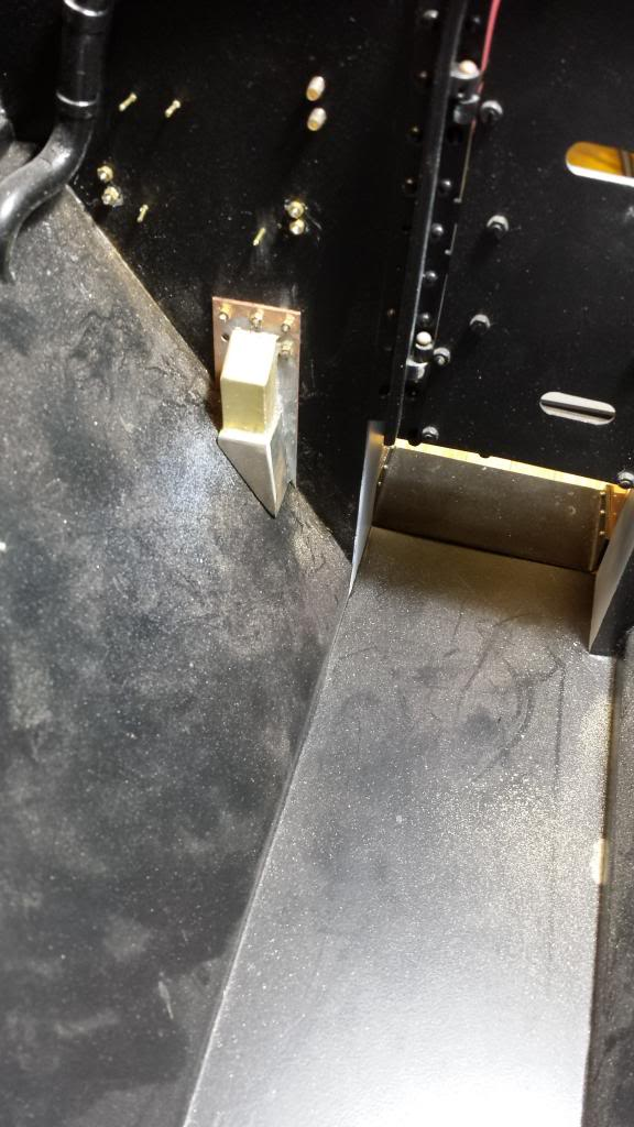
Next up was some more detailed work, this was a casing that sits inside the bunker, IIRC it covers part of the scoop apparatus that sticks out from the front.
This was a late addition as i had trouble finding photo evidence but a fellow ME came to the rescue, my apologies for forgetting who, so many have helped me with the project over the years, i'm indebted to each and everyone.
I tried to follow the proportions seen in the pictures supplied but I'm also forced to follow what's already built, ie the height of the locker and the slope of the coal bunker the end result being that the upper part is taller than seen in the picture I had but it looked ok to me and will probably be covered in coal most of the time anyway.. the protruding bolts and rivets will be sorted after painting as I need to be able to remove the parts they hold for painting.
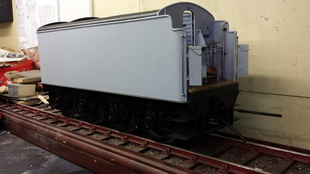
Now these last few pictures are really just to finish off the tender build so that I can move on to the engine, I'd say it's about 95% complete... jobs left are of course painting, lining, transfers and water filters.. I was hoping to find a commercial item of the correct size for the filters, so far I've found both smaller and larger filters, I've looked at motorbike fuel filters and even R/C car nitro filters which in fact came the closest but too small a bore, however I may copy the design and just increase the bore to the 1/4" that's required and then test to ensure flow isn't effected. There may also be a little work involved when mating the body to the chassis for the first time as it involves about 40 8 BA bolts but I can't see there being any problems. Other than that I think most is done unless I discover more bits to add...
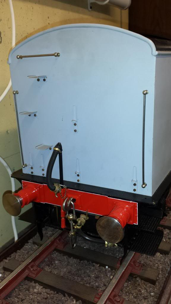
First view from the back, nothing much new here but included just to show all views at this point in the construction.
Low side view showing the lining..
General 3/4 quarter view
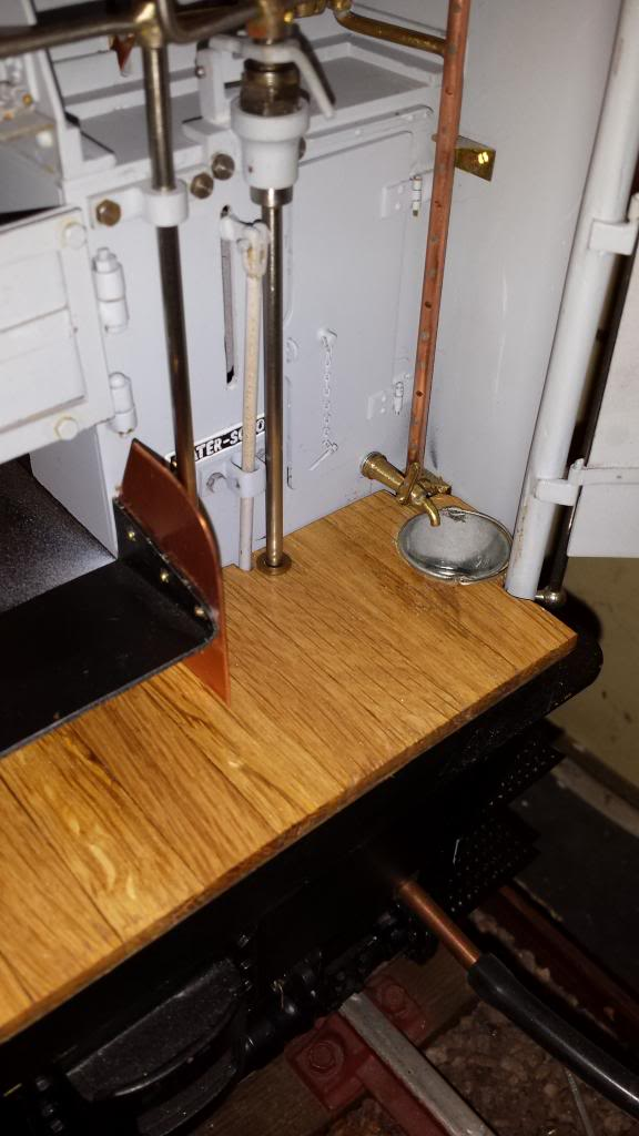
A close up of the front.... There's been a few changes here.. I have finally redone the wooden planking. New items..., lamp bracket seen on the left side as viewed, handle for locking the coal door closed, safety hoops that sit over the cab/tender doors, the two side shields fitted to the coal scuttle , the water gauge has had some of it's holes filled to follow the prototype closer and there is now the water tap that is below the right hand (as seen)locker. One thing to point out and admit to here and that's my error in fitting the two brackets on the water gauge side, I later discovered that these are for when the tender is paired up with an A4, the brackets are to hold the cod mouth handle, I might just leave these as is.
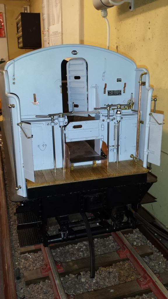
finally we have the fitting of the bucket that sits in the wooden floor, I found one of a suitable size from a dolls house supplier on eBay, once I had cut off the over scale handle and it's brackets and made up some new parts it looked much more to scale.