This update is going to look a bit strange as some bits may look 'out of step' for example I begin covering the fabrication of the steps and then the water piping, you'll notice in the last picture for the water piping that the steps are still as first made, hopefully this will become clearer as I proceed.
A little background on the steps, when I began making these I was still very much in my early days of researching the prototype, discovering new information more or less daily. The steps are a prime example of where I have revisited a part and changed it. Originally I covered the steps in a checker plate pattern, looked OK but I knew then that it was wrong but had no 30's pictures that were clear enough showing the steps in detail. Those on 4472 today made no sense to me, that is, they looked devoid of any tread pattern and in my minds eye not only looked wrong but looked dangerous too?
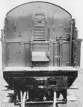
I then discovered two things, first was a picture of one of the tenders when new at the works clearly showing a row of what looked like rivets. I also discovered in one of my many reference books and from chats on the LNER forum ( I have an awful lot of reference books now), that as part of the apprenticeship training used in various locomotive works, one of the jobs that they were given was to fit a tread pattern to both the locomotive and tender steps.
From what I have read this was done in two ways, I guess it varied between works but in as far as a model is concerned the end result would look the same. Trainee's learnt how to weld and rivet by using these skills to apply a tread pattern to the steps. One method was to fix small rivets, the other was to weld blobs, both following the same layout, or at least from what I can ascertain. The picture that I found looked square on at the front of a tender where it was possible to count how many rows were used. It's not a very good image but when zooming in you can make out the rows, better on the left hand side steps (right hand as seen here).
There was some discussion as to whether I had this correct on the MECH forum but I stuck to my guns, later, much later, when being able to take photo's of the loco for myself at an early morning photo session at NRM in 2016, I could see that I hadn't made a mistake. The front steps which are probably those least used and weren't actually fitted to the loco until later in her career. The pattern was clear to see close up on the cab and tender steps but looks bare from a distance. Only when you get very close can you make out the remains of the old pattern, very worn but it is just visible around the edges.
a picture from the 'no tread camp' that was presented to me as proof..you have to admit, it looks pretty convincing..:)
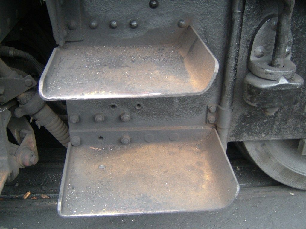
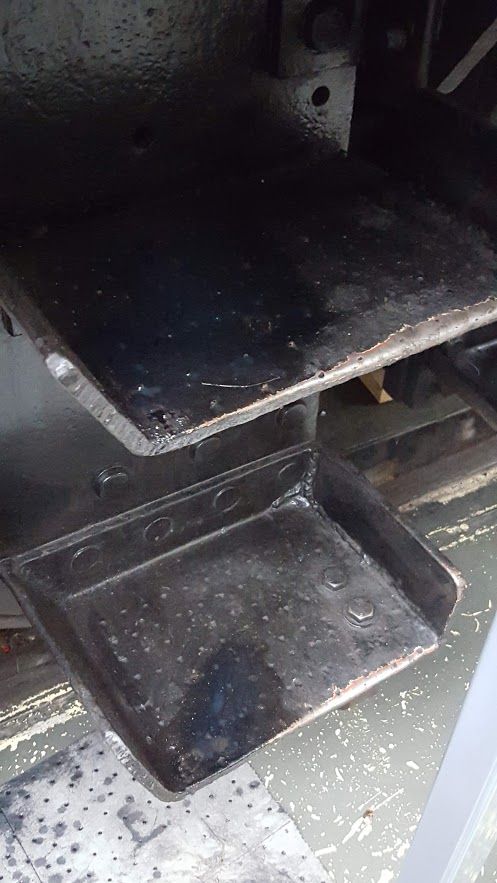
And here we have a couple of my photos from 2016, first the loco front step.
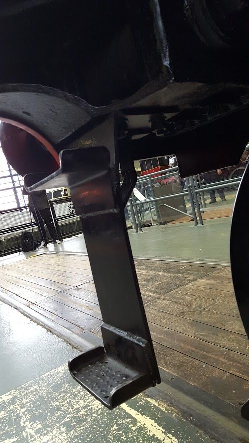
and here's the cab steps, you can just make out the same pattern as that seen on the front steps. It probably shows up more in this picture when compared to the one presented as proof that there is no pattern due to the loco being fully cleaned for display.
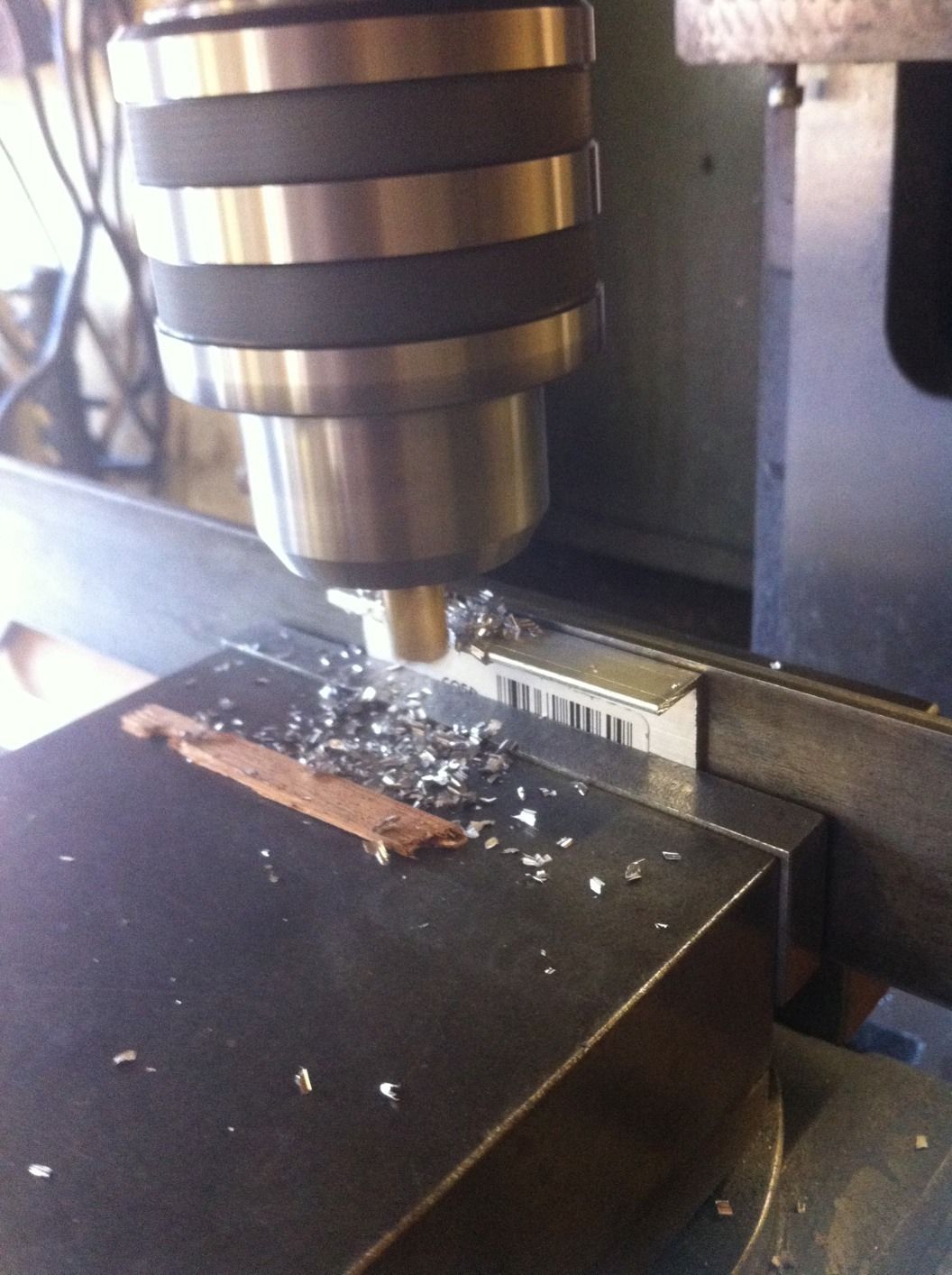
Ok, so on to the model itself... While roaming around B&Q I came across some Alloy extrusion which after machining was ideal for the job in hand. The picture shows on of the steps cut to length and now being machined down to size, I even left the bar code on as proof its a bought item... :)
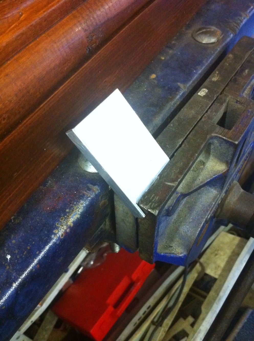
After machining to size and squaring up the flat end ,a small slot was cut to allow for the bend as shown here after which the step was completed by filing the curved angles to shape. One of the changes made later was to also do the same to the other end of the step, something that is not shown on Don's drawing. The steps vary in shape and style, I have tried to followed those as can be seen in photos.
Steps loosely fitted in place and still showing just the single turned up lip
I had posted a picture on the LNER forum of my tender during my many researching sessions and it was pointed out that Doncaster works didn't use the pattern that I had used (checker plate mentioned previously) so it had to go. After researching a little more and with help from the forum mentioned it was discovered that the step tread was created with rows of 1/4 rivets/weld blobs, which was confirmed by a picture that I already had although evidently I hadn't paid enough attention to it (now shown above).
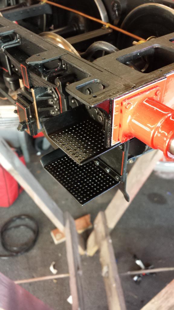
So here's what I have done, these are 1/32 rivets which are a little bigger than required but I think it only equates to there being 1 row missing, I can live with that.
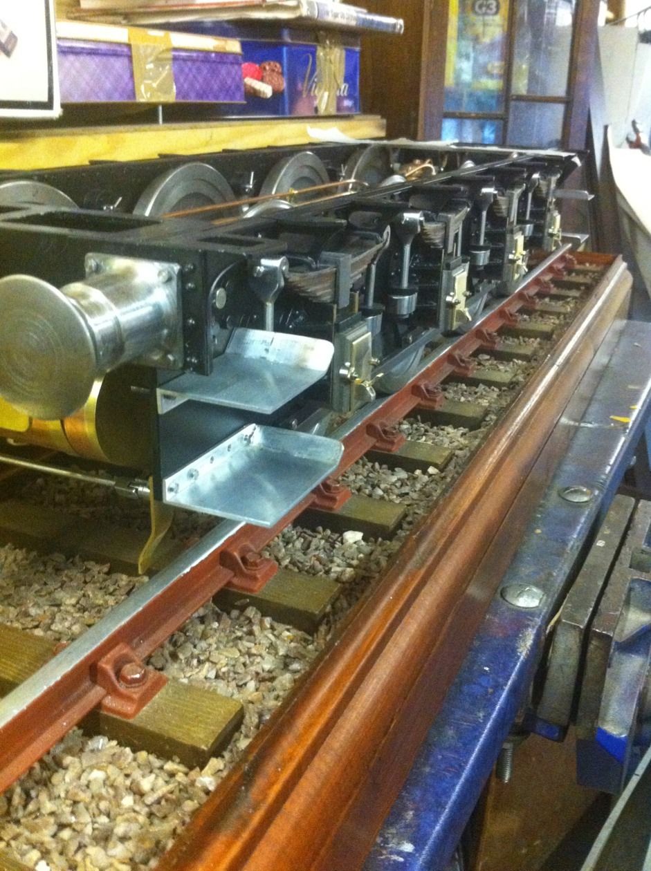
Well this was a lot of work but got there in the end.. steps now finished and refitted to the chassis along with the guard irons. I'm glad that I spent the time on these as they would have looked a bit plain if leaving them without rivets and to me they look so much better, practical and more prototypical than previously seen.
NB: as you can see, the chassis is fully painted in this image, that's because I have taken it out of sequence to help explain the step construction.
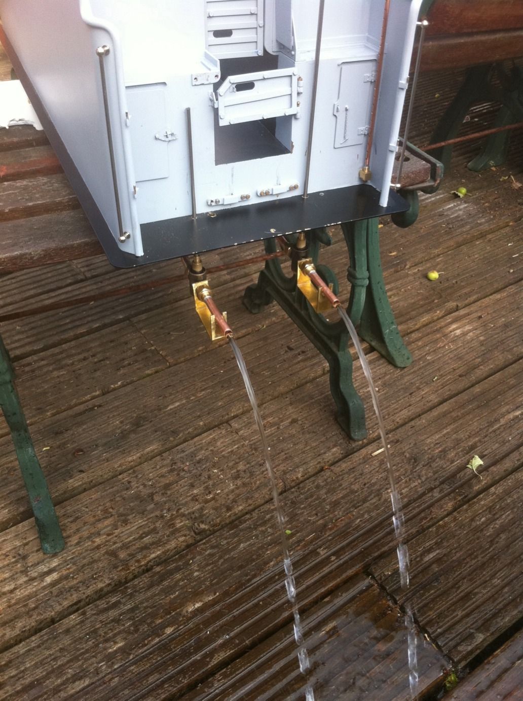
We now move on to the water piping and a test on water flow.
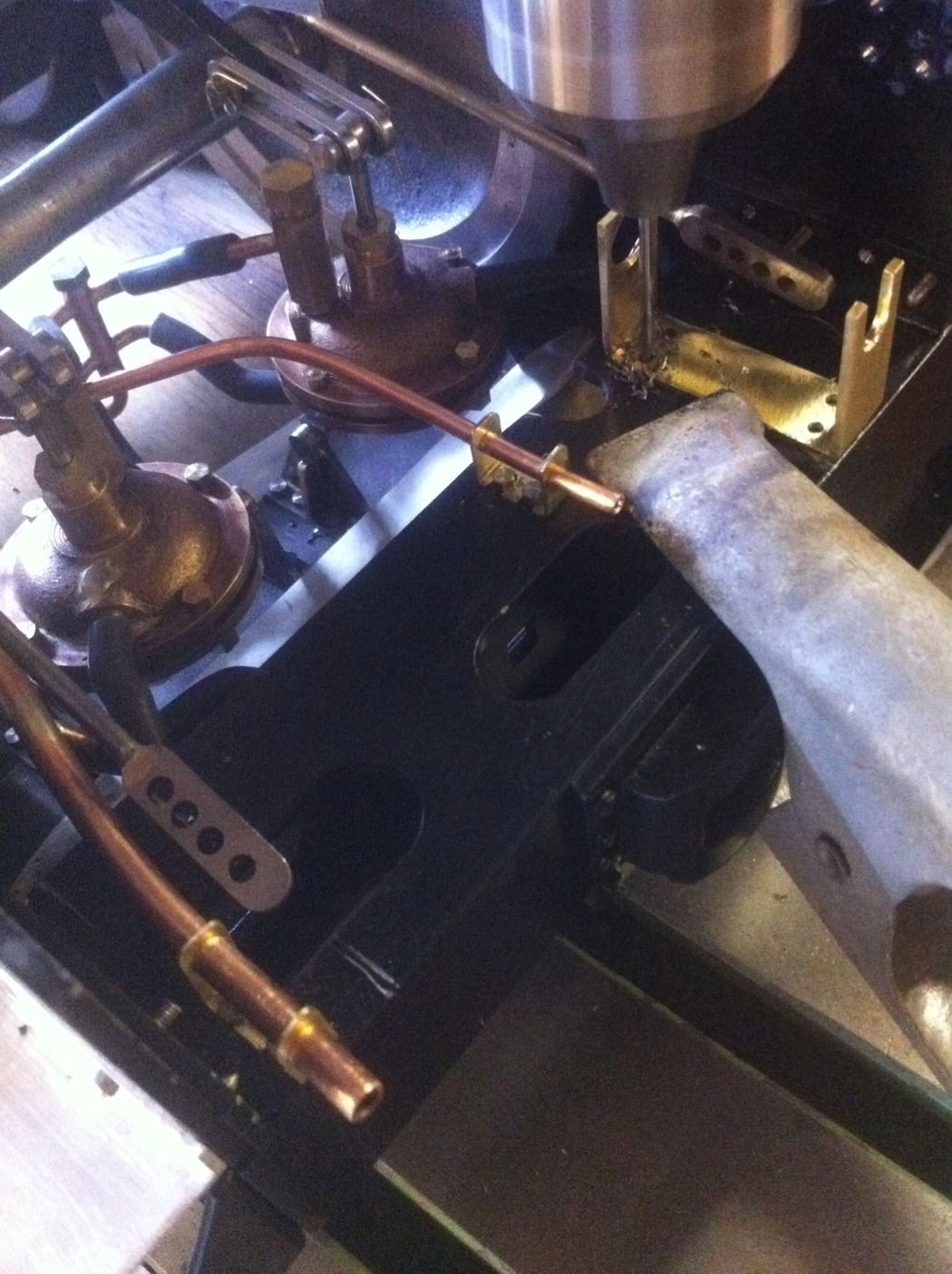
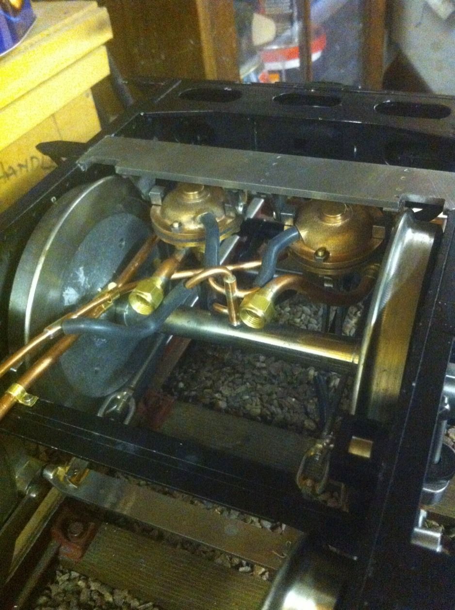
The picture shows a test of the water valves working to check performance before final fitting to the chassis.
Items used are 2 x 90 degree 1/4" tender water valves supplied by Bruce Engineering, connection to belly tank via 2 x 1/4" by 3/8 x 32 thread unions.
Test result was good, flow rate was very good and no leaks from tender which was filled to the rim for the test. Also the tank emptied a look quicker than I had thought so see no reason to fit a drain plug as I had originally planned.

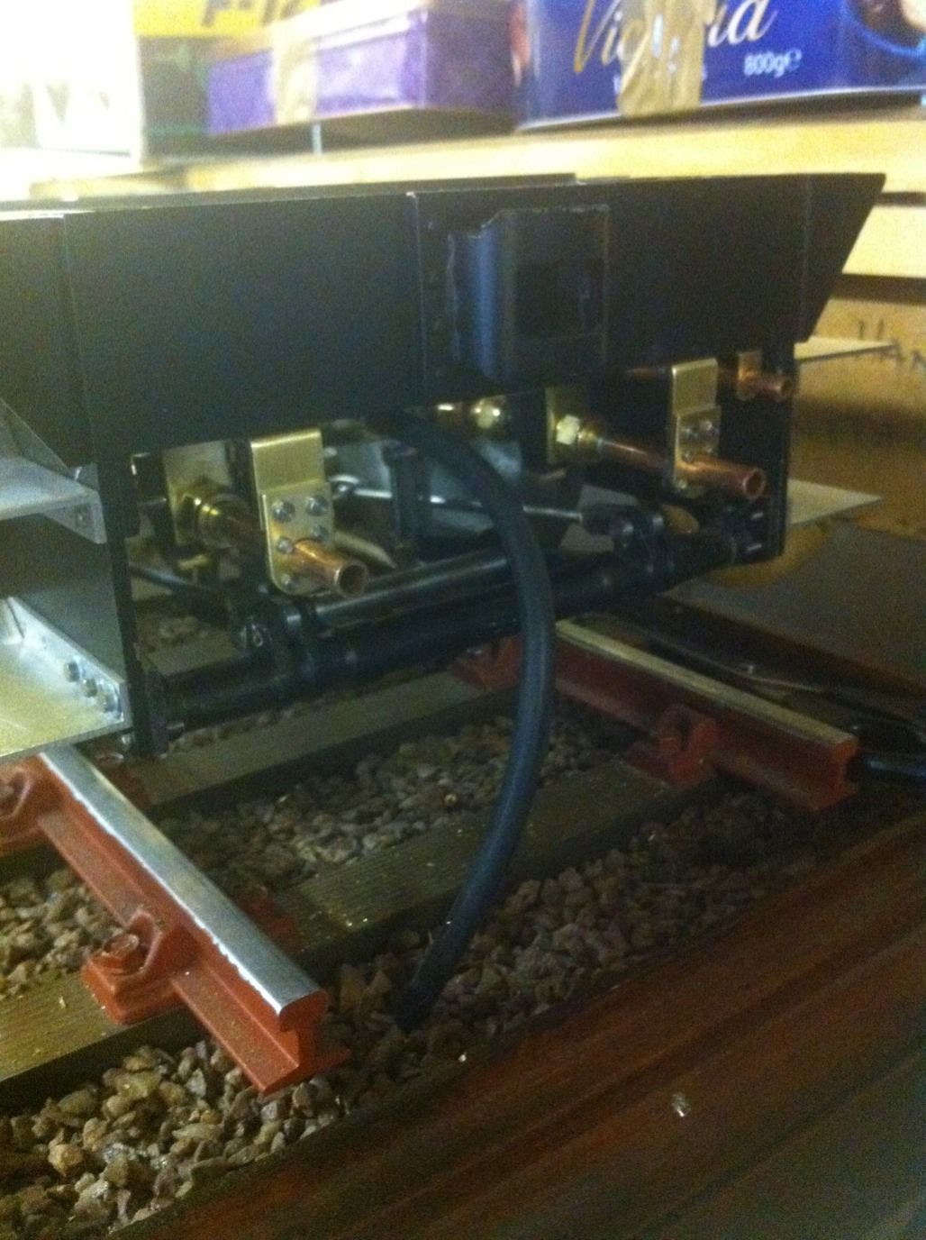
Mounting U brackets to the underside of the draw box to hold both the brake vacuum and water pipes in place via 8 BA hex bolts. I have tried to replicate the general appearance of these brackets as seen in some of the photos of full size shown by Don in his words and music.
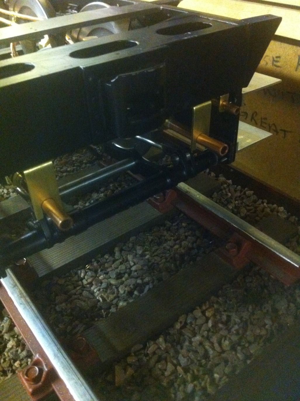
early beginnings of the brackets and pipework fixed to chassis, these have been laid out as per prototype.
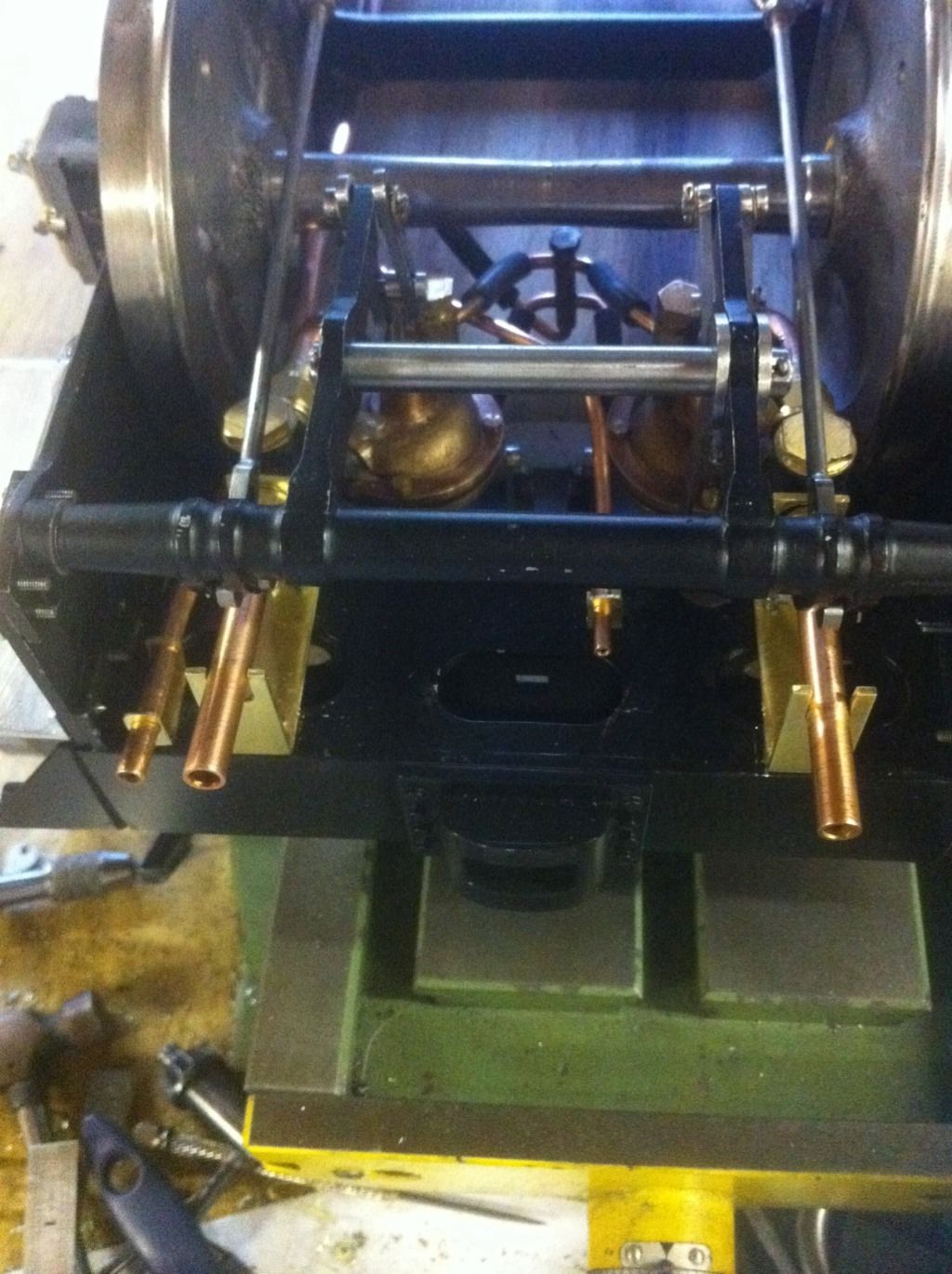
View from rear showing the two 1/4" pipe connections ready for fitting to the belly tank. After looking at this for some time this seemed the best place for disconnecting the water pipes to remove the tender body for future maintenance as I can access these pipes without to much difficulty.
NB:.. Now I had forgotten something at this stage and that's the planned inline water filters... I have yet to make these, just another one of those many outstanding jobs left to do.
Rear view, I have some more detail work to do here that as mentioned will follow a picture supplied in Don's words and music, I want to try and get as close a prototypical look for these connections as possible and yet still be practical.
A closeup of the water pipe bracket now with it's finer detail applied.
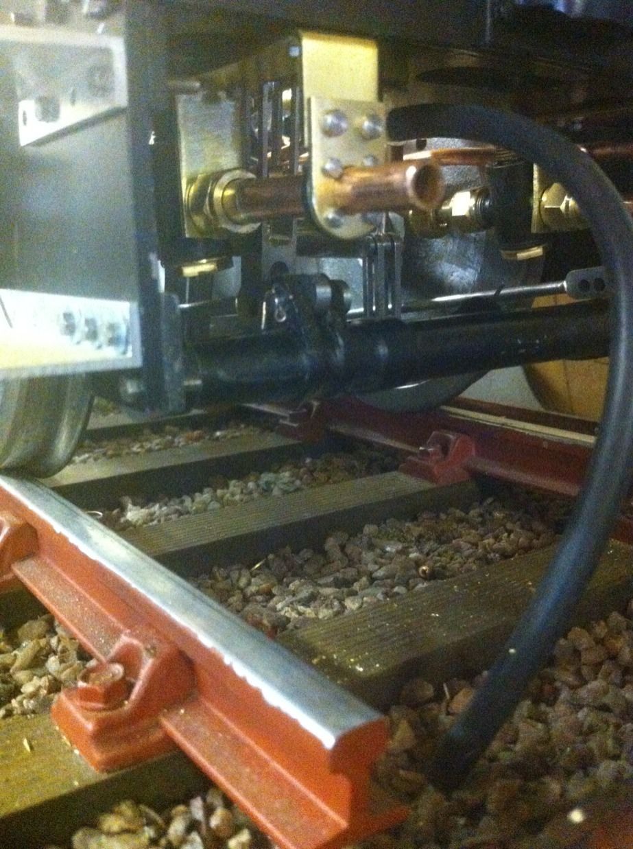
A general wider view of the pipework showing the two water pipes for the injectors , the 3/16 main vac pipe to the engine and the smaller 1/8 vac pipe that's set back as in the prototype photo. On researching this it seems that things varied a lot on different tenders so I've used a little modelers License in doing this but I think overall it looks good?