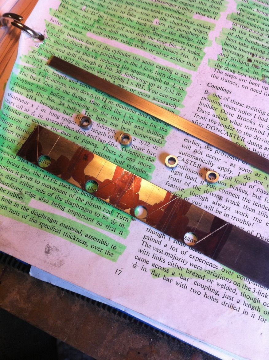
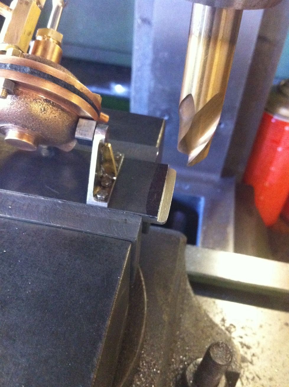
Brake cylinder support brackets, I've deviated from Don again ( making a habit of that) both in method and design. Don states to bend up the brackets from 1"x 1/16 steel, drill 1/4 hole for bearing which is turned to suit the fulcrum pieces ( next) , braze all together and shape to drawing. I wanted a sharp 90 degree bend with no radius so decided to make the brackets up from two separate pieces.
The picture shows the various parts ready for brazing, rather than make all the parts separately I find it easier and quicker to construct as one piece and then to split them up for final shaping. I soft solder the web piece on after these parts were silver soldered and cleaned.
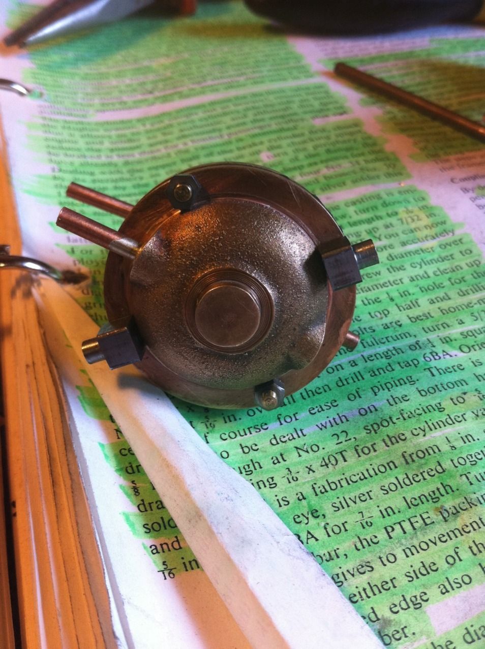
Here the fulcrums have been machined and fitted to a cylinder, they start of as 1/4 BMS sq bar chucked in the 4 jaw and 1/8 spigot is turned down to 5/32 dia and the the job is parted at 5/16 overall. Finally a hole is drilled into the 3/16 length of 1/4 sq bar and tapped 6 BA.
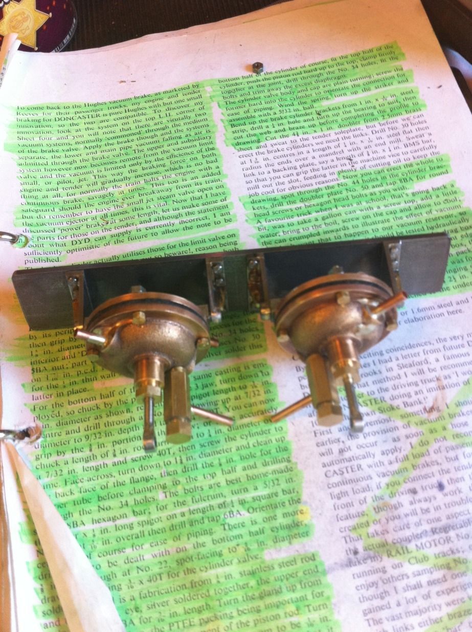
Cylinders fitted to brackets and doubler plate. Now I have changed things again here in as far as the doubler plate is concerned. Don says to cut the plate from 2.5mm brass to 4 3/8"x 1" size and then sweat it to the soleplate. Mark and then drill 16 No.44 holes and tap 8 BA for the brackets . Now the problem here is to remove the body I'd have to dismantle all of this first and that would be a pain, also I wouldn't be able to observe the brake operation for final setup with the body in the way, yes I could turn the chassis upside down but then the brake geometry would be all wrong so I've changed things a little and perhaps others may wish to follow.
Ok so I want the doubler to stay with the chassis, there's a few things to consider . First the doubler needs to be longer to fit across the frames rather than between wheels, it needs to be stronger as it will be self supporting and it needs to have sections removed for wheel clearance. Here the chassis has been clamped to the mill bed, it's at times like this that I'm glad I bought a mill with a large bed. Naturally the doubler must be flush with the top of the frames so first job was to machine a step ( 1.6 mm deep, half doubler plate thickness) in both frames having first worked out the correct position above the brake shaft.
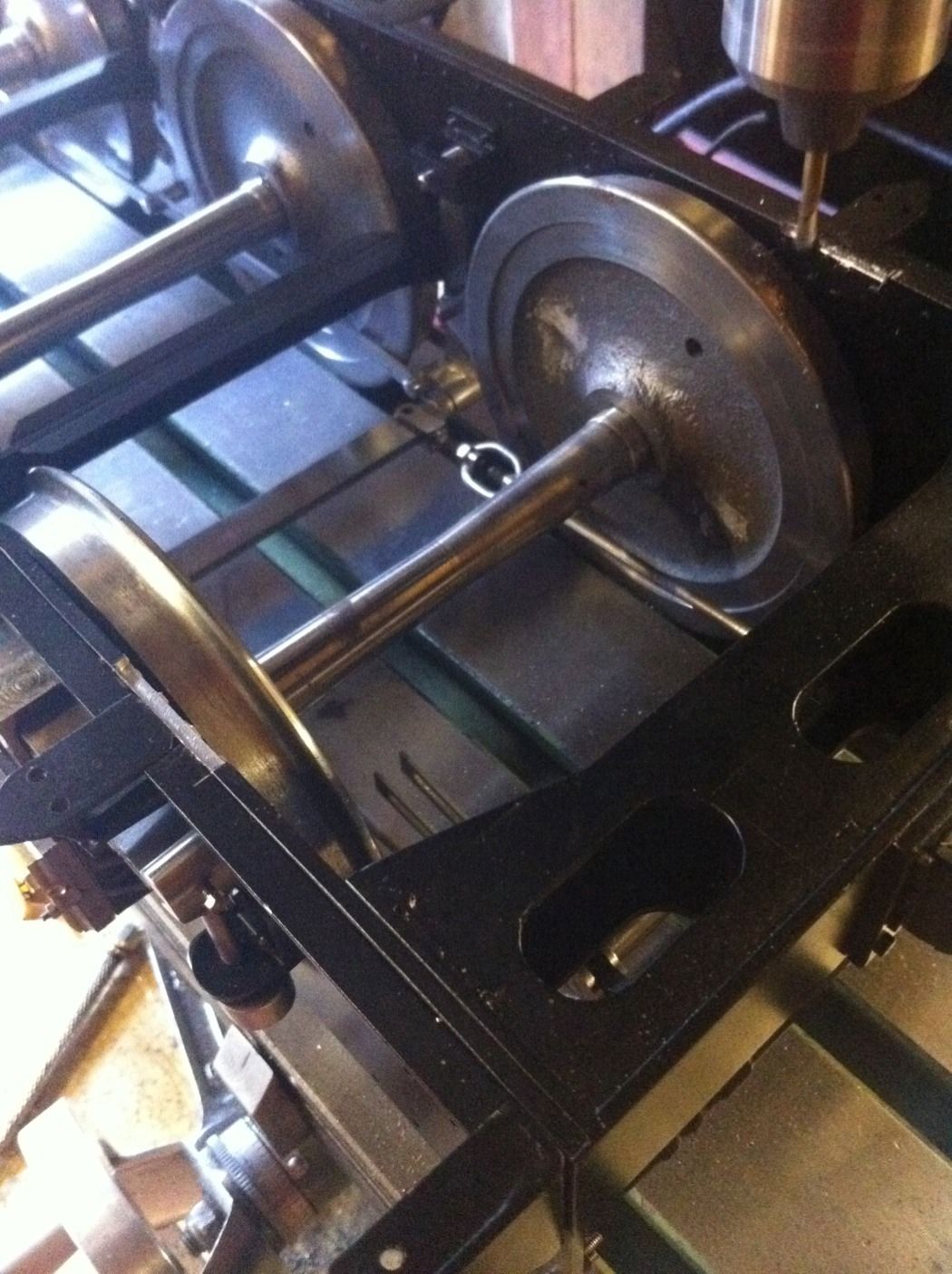
Then machine a corresponding step underneath both sides of the doubler plate which is now 1/8 steel instead of the 2.5 mm brass.
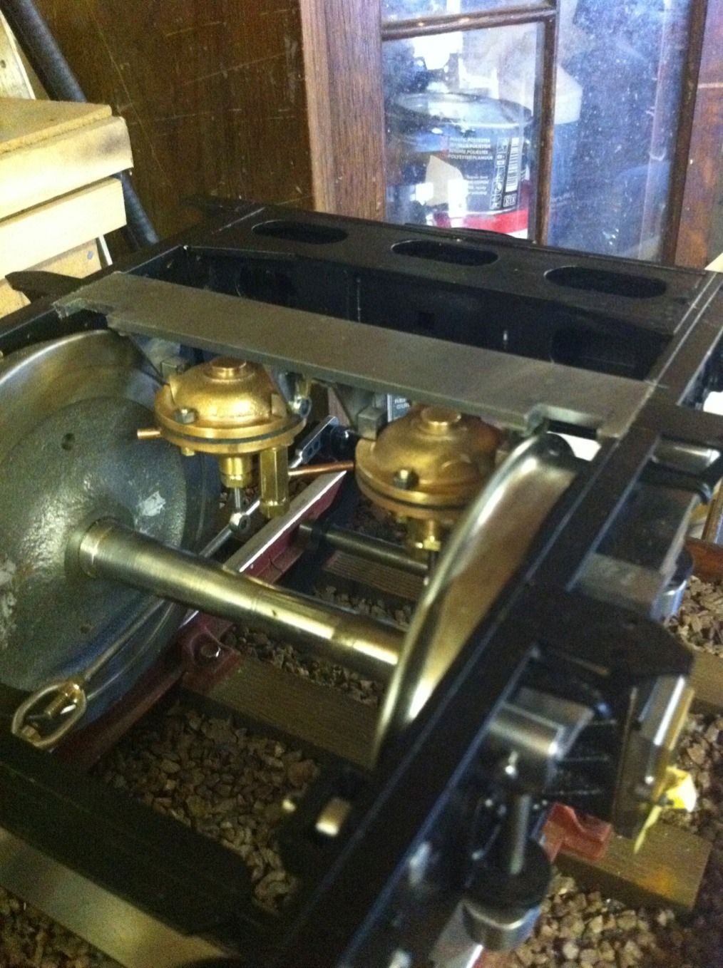
Doubler plate fitted, note the recesses cut to clear the wheels. The plan is to leave the plate like this as it will be held firmly in place once the tender body is fitted on top since it will be trapped between the frames within the machined steps. However if in practice this proves unsatisfactory I can remove two rivets from either side that currently fasten the 1/4 x 1/4 x 1/16 right angle stiffeners and replace them with 8 BA hex heads having first drilled and tapped to suit, this may require some 1/4 sq supports being soldered to the underside of the doubler plate first but that's easy enough.
NB: now being much further into the build the extra support discussed above is not required.
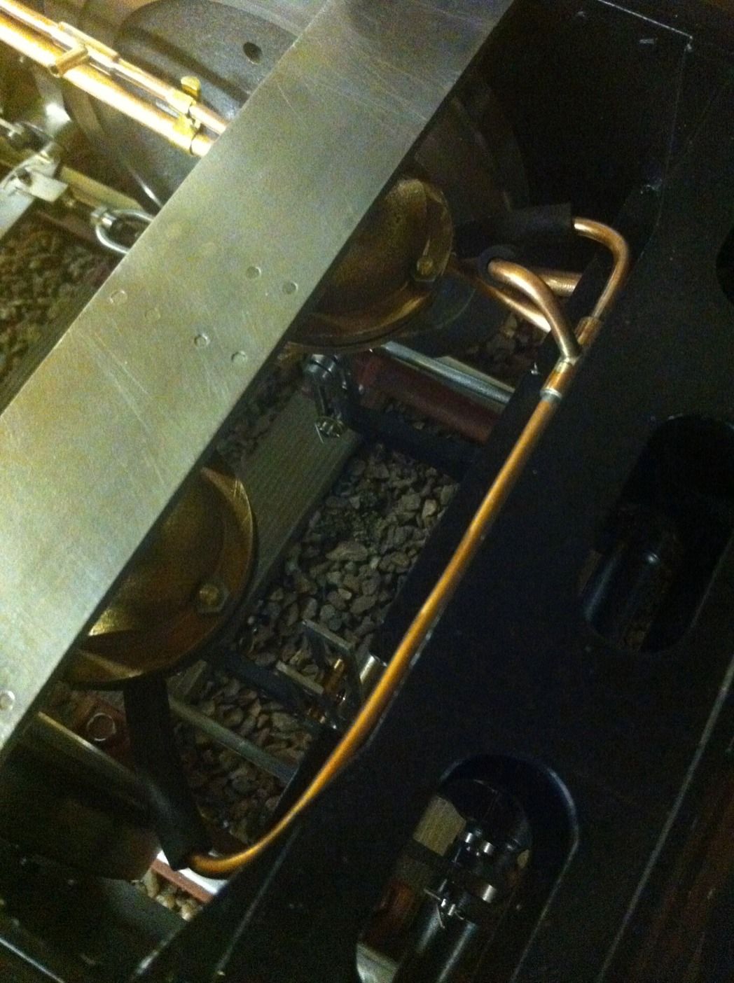
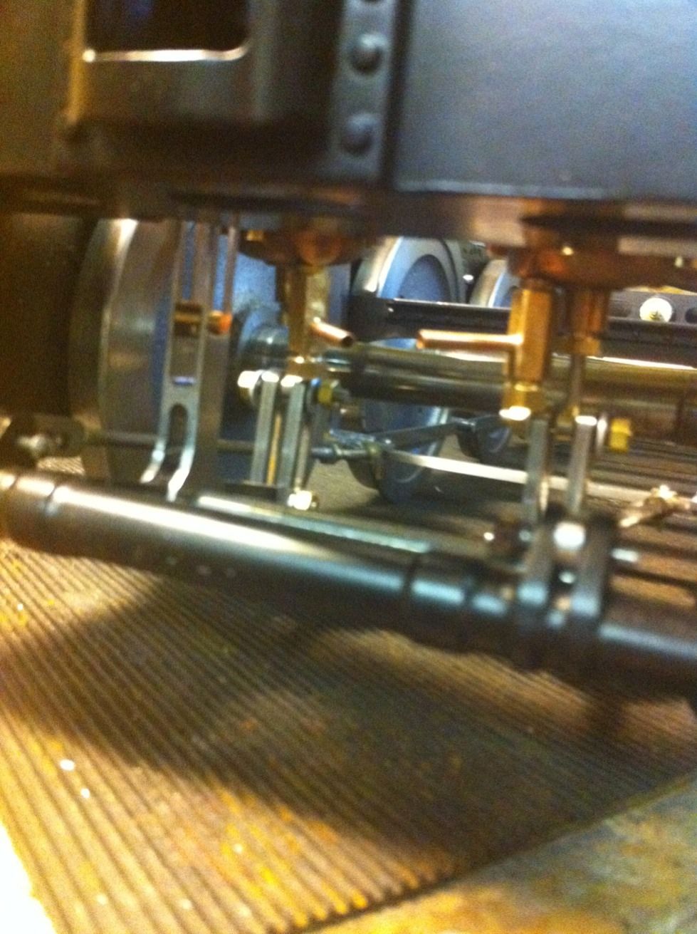
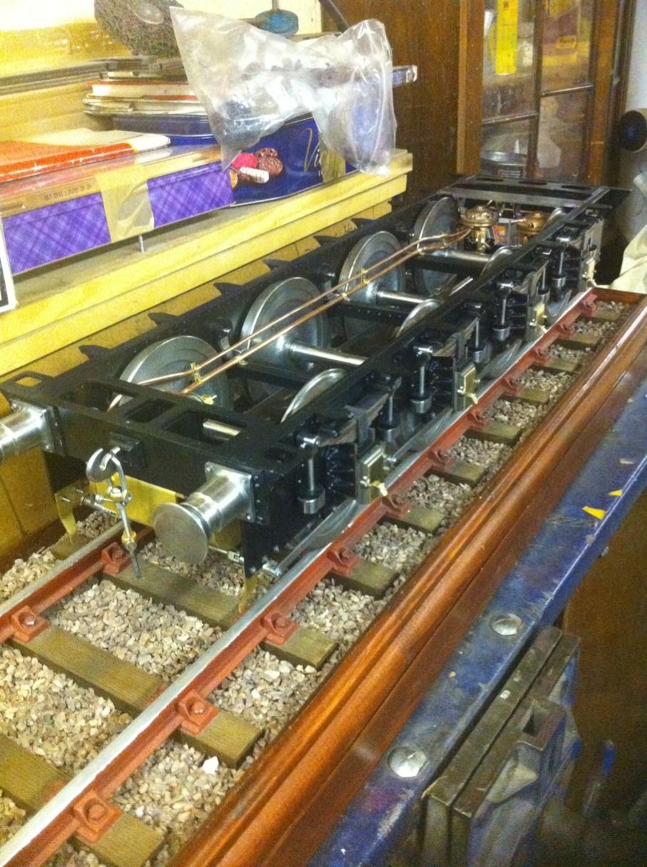
Here we see the progress so far, as you can see it's getting a little busy under there. The links between brake shaft and cylinder are lengths of steel that after having the two No.30 end holes drilled they were then joined by chain drilling with No.37 bits and then machined with a 1/8 slot drill. The pins connecting them in this picture are temporary until I later found the energy to machine some up. The links are made of a thicker material than to drawing, 1/4 x 1/16 seemed just a little fine to me so I beefed them up to 3/16 x 1/8.
I then spent a few days doing a few little bits and pieces so I'll add the pictures here now so that they don't get forgotten.
The axle box covers were profiled and the oil tray lids given 14 BA round head screws acting as pins, these are a tight fit and have no need of nuts to secure them so once painted will look like pins .

Not a very clear picture but the correct pins have now been made for the cylinder links, as mentioned I had beefed these up but decided I had gone a little OTT so then machined them down a little but still thicker than drawing. Although they did clear the valves they were a little close for comfort hence why I've reduced them.
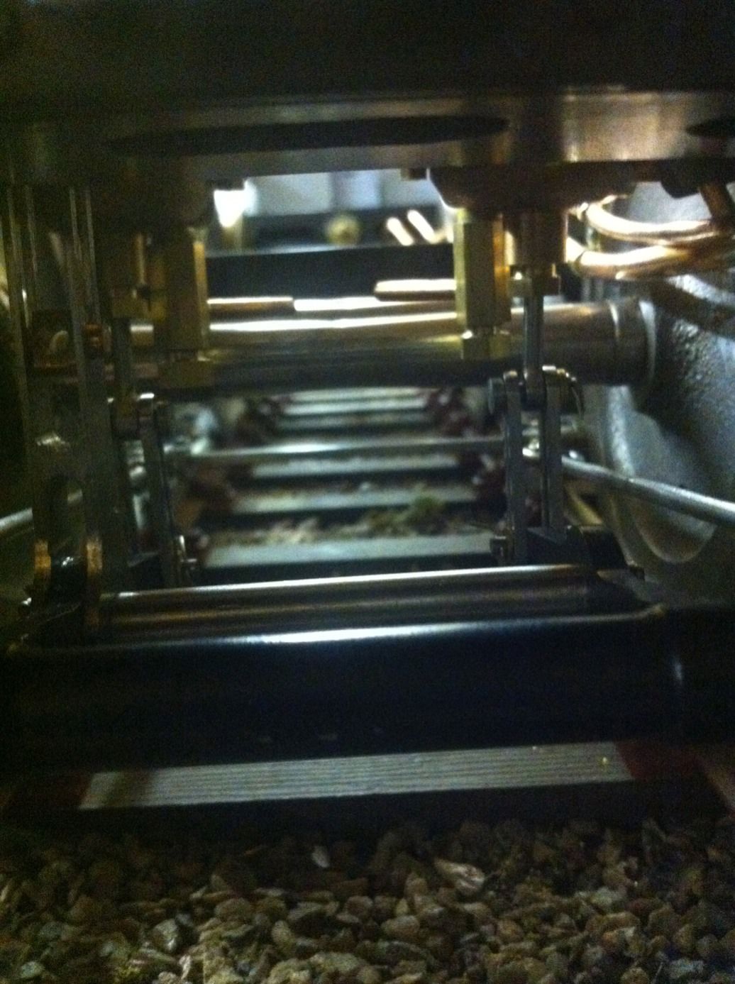
I then ran the two vac pipes for the brakes although not all connected yet. The main engine vacuum pipe feed is 3/16 and the smaller pipe from the reservoir tank is 1/8. I made up some P clips which hold the 3/16 pipe to the intermediate stays with 8 BA hex bolts, the 1/8 pipe is attached to the larger pipe via clips made up to hold the two pipes together. Both the 3/16 and 1/8 pipes have Tee's soldered on, both of which are 1/8 for connecting to the vacuum cylinders using silicon tube.
Here is the pipework that connects to the cylinders between the main 3/16 engine feed pipe and the side of the cylinder diaphragm that holds the brakes off. I bought some 1/8 ID silicon hose for connecting these pipes up .
The cylinders pivot on their fulcrums to allow for suspension movement which means this pipe needs the flexible connections to work and since it's so small I'll leave it to float not that it will move much.
NB: Having now made the pipework for the locomotive brakes I may change this connection to that on the loco which is much better.