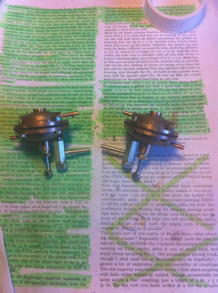
Dons 'Doncaster' has 4 cylinders , 2 each for the loco and tender. these are vacuum controlled and incorporate an auto-braking system. This again is as per prototype. I have tried to cover the fabricating of these cylinders in as much detail as possible whilst keeping it simple, please forgive the clarity of some of the photo's, I promise things will get better as the build continues.
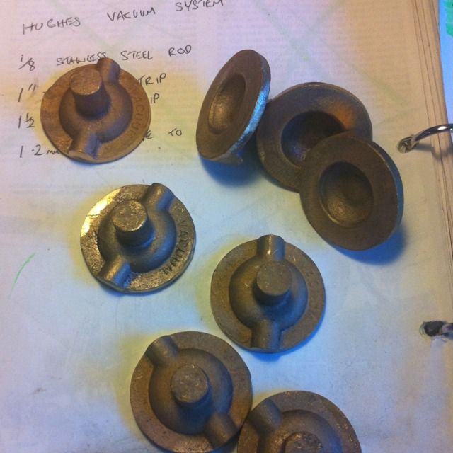
The picture shows the 8 castings which are identical but the tops and bottoms are of course machined differently, many of the lathe set ups though are shared.
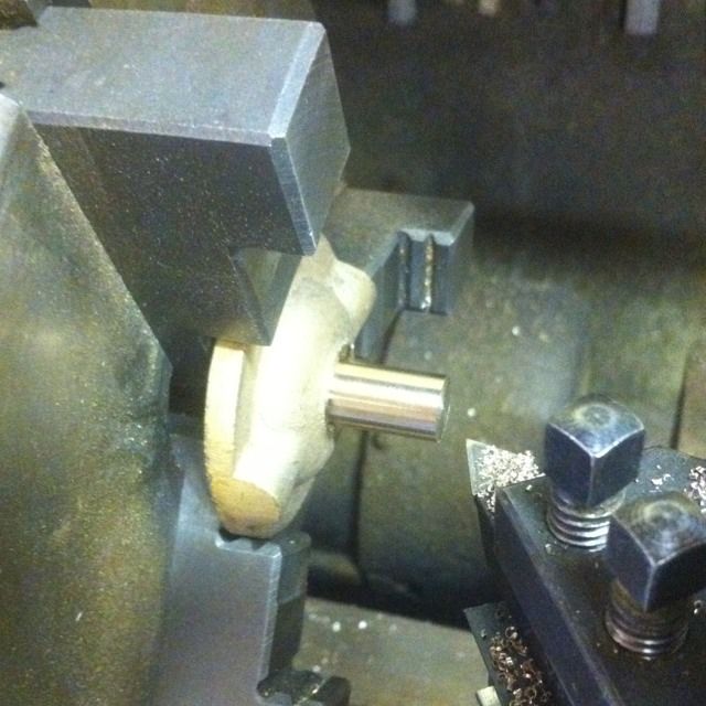
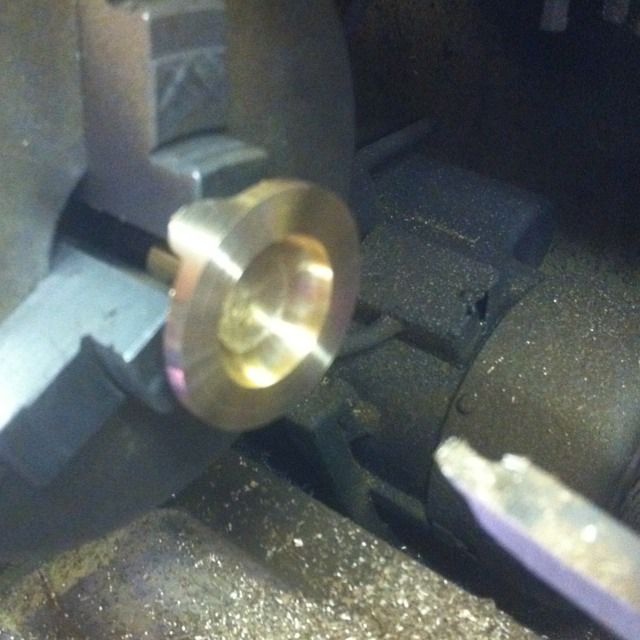
Using the exterior jaws in the 3 jaw all 8 castings were held by their periphery's and the spigot is faced and turned to 3/8". The backs of the castings were, of course, first filed to remove any high spots before setting in the chuck
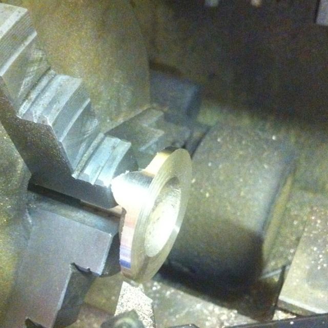
They were then reversed in the chuck, faced and turned down to just above 1 5/8 dia.
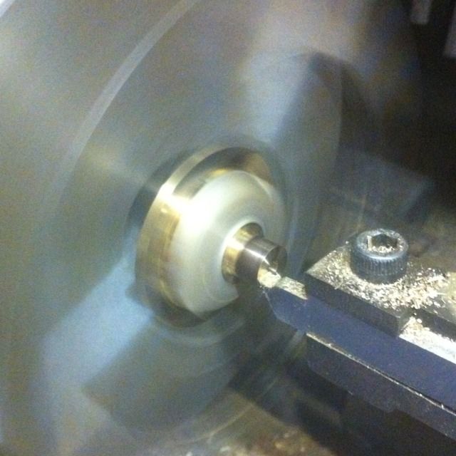
Now Don made no mention of cleaning up the inner chamber but I did it anyway, using a suitable length of tool steel I profiled it to the inner radius and cleaned up the chamber as shown here.
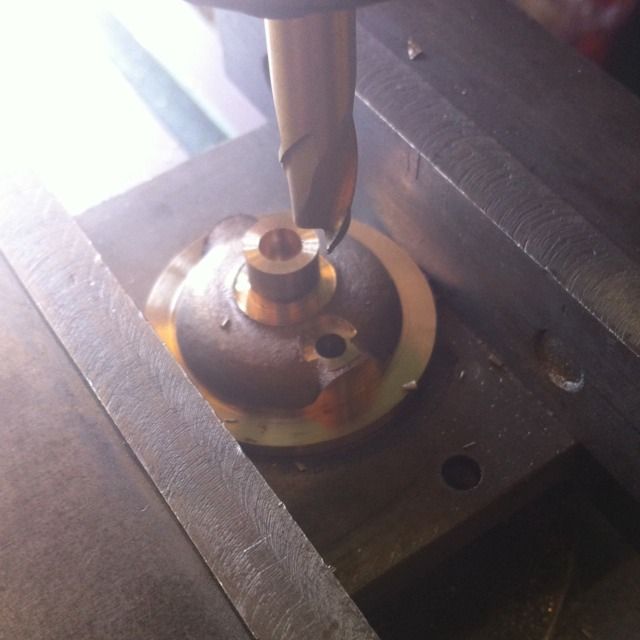
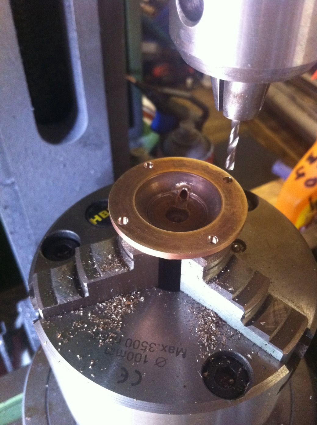
This is where things differ between the two halves, first the tops. Using a 1/4 end mill, a 1/8 deep recess is machined to give clearance for the 5 BA nut that sits at the top of the diaphragm.
Then the back face was machined leaving the rim 1/8 thick and stopping just as the outer casing of the chamber is reached.
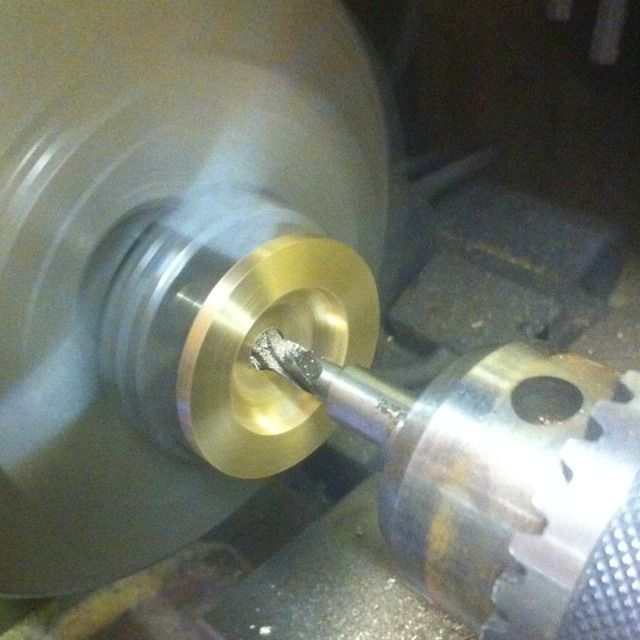
The next job was to reverse in the jaws and machine the spigot to 1/8, I forgot to take a picture of the top at this stage but this is the bottom having it's spigot faced although it's longer at 5/16. Other jobs for the top before this stage was a No.30 center hole drilled , followed buy a 7/32 hole to a depth of 9/32 ready to be tapped 1/4 x 40 T at a later stage.
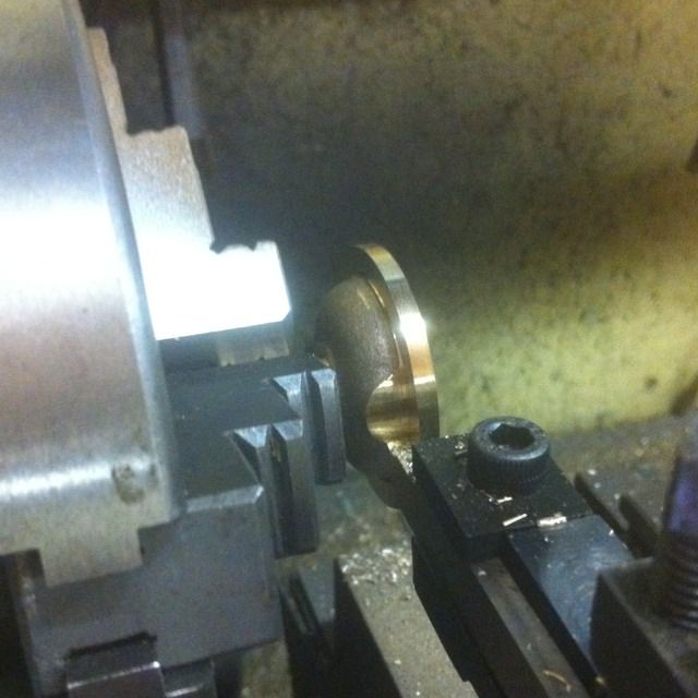
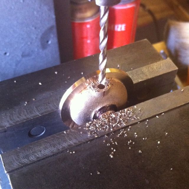
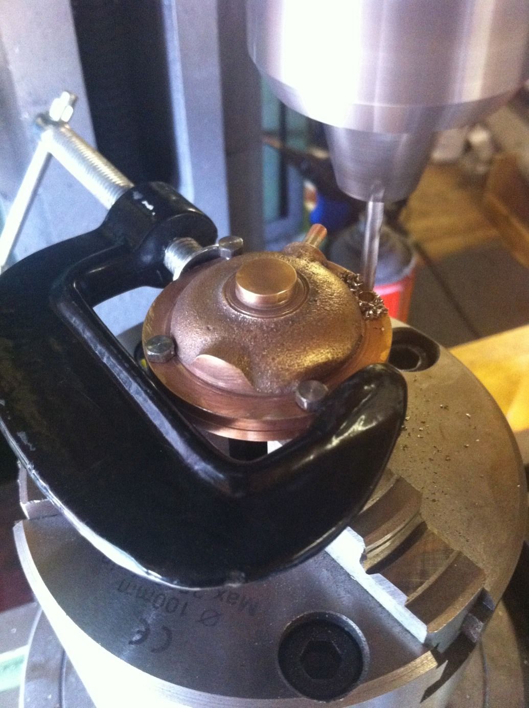
All 8 cylinder halves then had a No.30 hole drilled into the side of each chamber to accept a 1/8 copper tube, for this I used the machine vice.
The bottoms then had a No.22 hole drilled ( tapped later 3/16 x 40 T) on the opposite side to the 1/8 tube which is also spot-faced with a 5/16 end mill. This will be for the cylinder relief valve body to locate in when made..
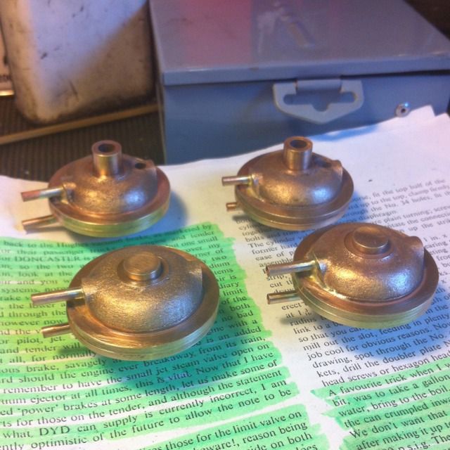
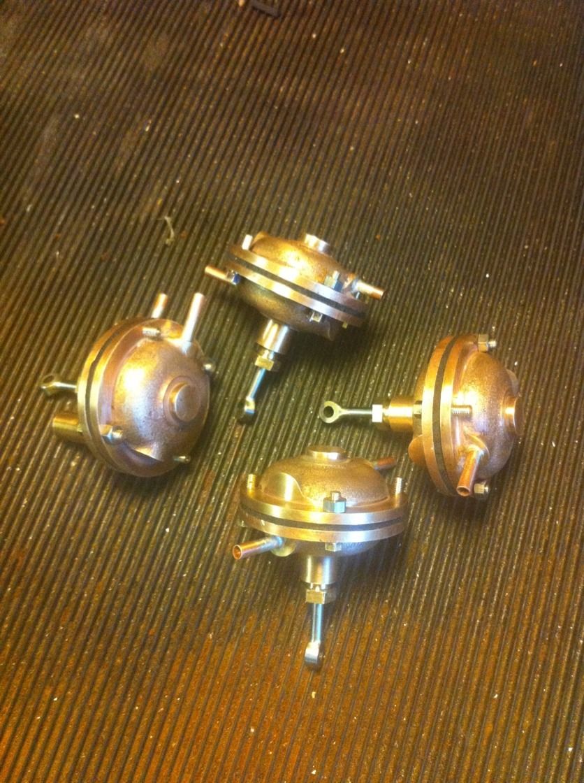
The 4 cylinders so far, jobs left to do here is the 4 No.34 holes around the rims to hold the two halves together and the various tapping to do.
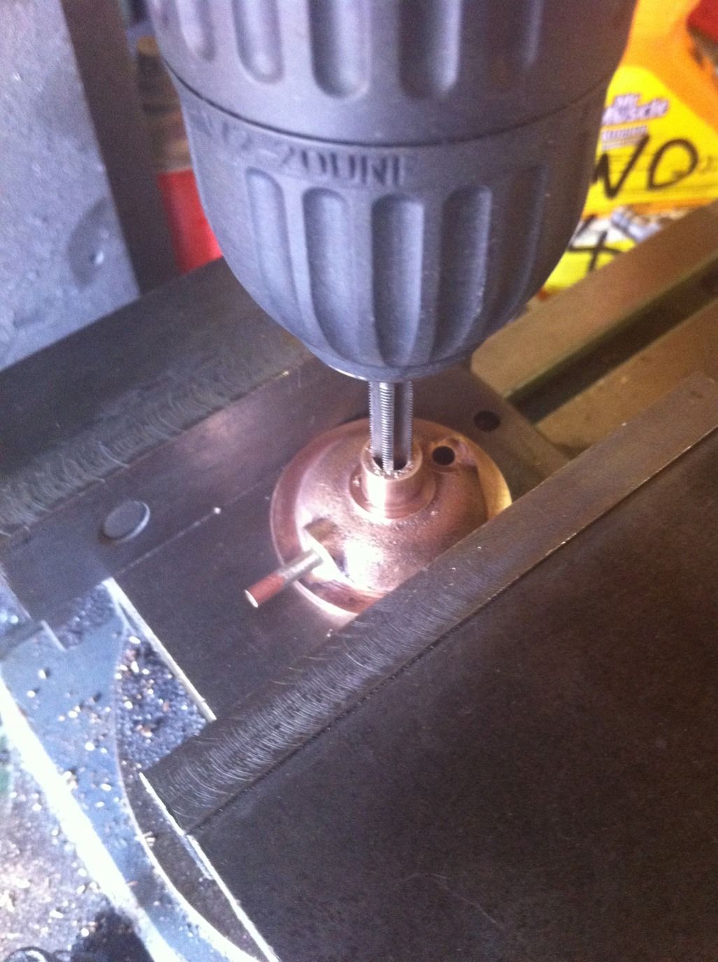
Here the two holes in the bottom half are being threaded, center one for the piston rod gland nut is 1/4 x 40 T and the other for the cylinder valve is 3/16 x 40 T.
The cylinder halfs were then moved to the rotary table for the 4 No.34 holes, this is one of the top cylinders
I then moved on to the bottom half which after securing in the rotary chuck the process was repeated with the top half laid on top. After drilling the first hole a 6 BA bolt inserted to align the parts and the other holes where then drilled using the top half as a register for the remaining 3 holes.
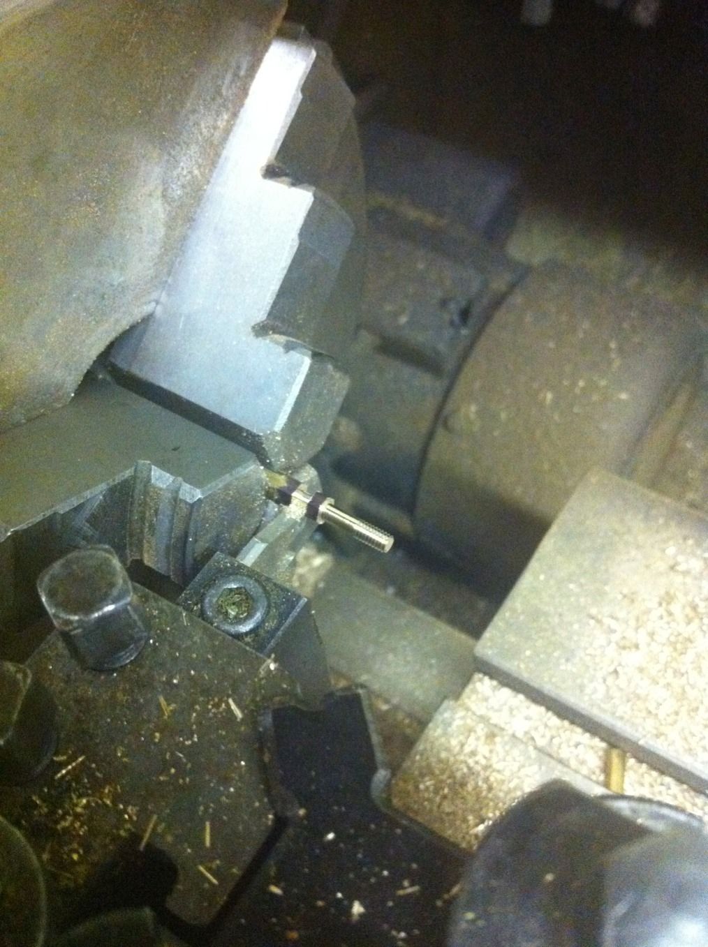
The securing bolts had to be turned up from bronze hex bar as they are locating type requiring a plain shank section for good fit into the No.34 holes and then threaded 6 BA.
I have to say even though there are only 16 of them it's a soul destroying job making bolts from bronze, at least I think so..
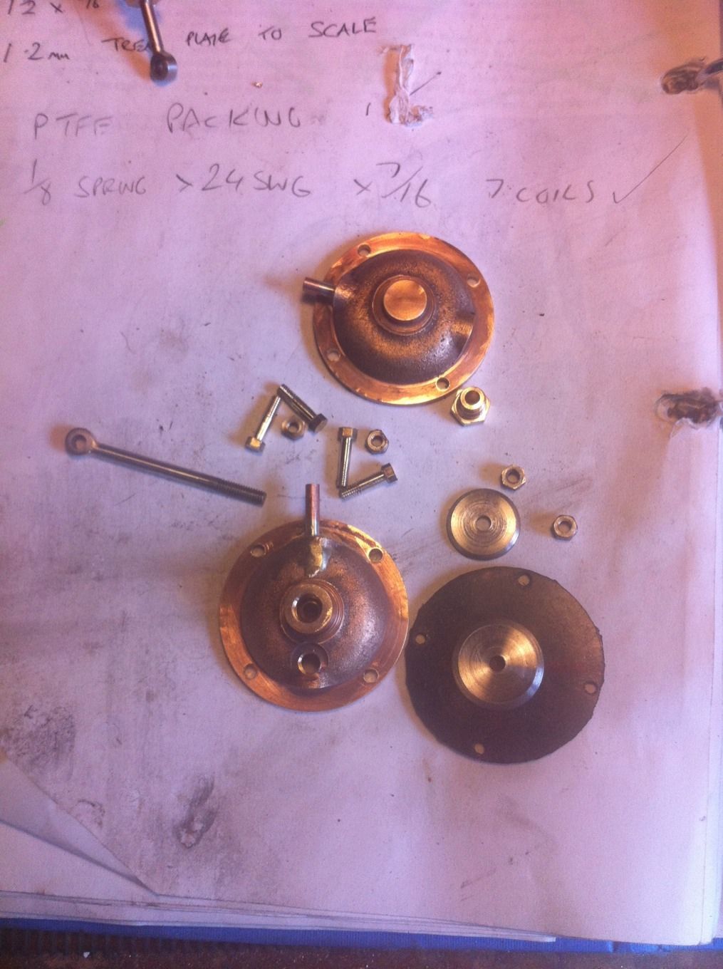
Rather than give pictures for all of the parts that need to be made I'll show what's involved here and describe all together.
Piston rod: from 1/8 stainless steel, overall length is 1 9/16 with 7/16 threaded 5 BA. The eye is 1/4 BMS drilled No.30 and 1/8 thick to match rod.
Gland nut: 5/16 A/F hex bar turned down 1/4 for 1/4 and threaded 5 BA
Diaphragm disks are both 1/16 thick, top is 5/8 dia and bottom 25/32. They are chamfered to stop the discs cutting into the diaphragm.
Diaphragm is 1/16 rubber. This was trapped between both half's, holes drilled and then trapped with the bolts, it was then a simple task to trim the excess with a scalpel.
Everything here had to be made which took a little time but I'm happy with the results.
NB: I later changed the 1/16 rubber diaphragm material to a cut up inner tube, i got this tip from elsewhere (sorry forgotten who) and have to say that in gave a lot more movement for the piston rod not having to fight as hard against the previously used material, thank you to who ever you are...:)
And so we have the finished cylinders, the piston rod eyes are aligned so that they will line up with the brake shaft once fitted( more about that when I make the support bracket)
Other thing to mention is the 3/32 PTFE packing used for sealing the piston rod assembly.
Testing via sucking the inlet pipes proved that all 4 cylinders work well both opening and closing.
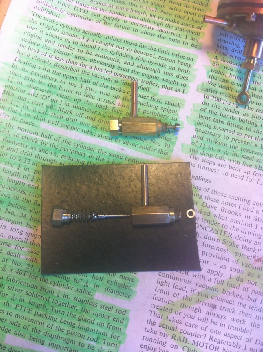
Here are two of the cylinder valves, one left in component form to show what's involved. These were mainly simple turning although it had to be accurate for the striker pin to work properly. The valve body has a turned spigot at one end that is threaded 3/16 x 40 T to fit into the cylinder, there is also a No.47 hole drilled this end for the striker pin to poke through. From the other end first a 1/8 hole is drilled to a depth of 5/8, this is then opened out to 7/32 for 7/16 of which half is tapped 1/4 x 40 T to accept the end cap that also holds one end of the spring central via a small recess. The striker pin is 3 mm BMS turned down to 1/16 for approx 15 mm and then parted at 17.5 mm overall. These pieces fit together in the order seen here, I made a slight modification to the striker pin, the pin seemed a little close to the bottom disc in the vac chamber so I threaded the end 8 BA just enough for a nut to fit and lock in place at the correct height, the nut was rounded off a little do that it cleared the 3/16 x 40 T thread without fouling. Last job was to drill and silver solder a length of 1/8 copper 5/8 from the spigot end, the valve had been screwed up tight first to make sure the tube was fitted to the correct hex face and was trimmed to length once all components were fitted and piping was run.
The finished tender cylinders, the two loco cylinders are also nearly finished accept for the 1/8 copper tube outlets on the valves, I won't fit those until the loco is built and I know what clearance of have around the valves to work out which hex face to fit the tubes too.
It was pointed out to me that vac brakes didn't have a lot of movement, I couldn't test the full movement at this stage but at the time seemed not much over 1/4". I later discovered once the tender was almost complete that the brakes work very well, they don't need much movement to do their job properly.