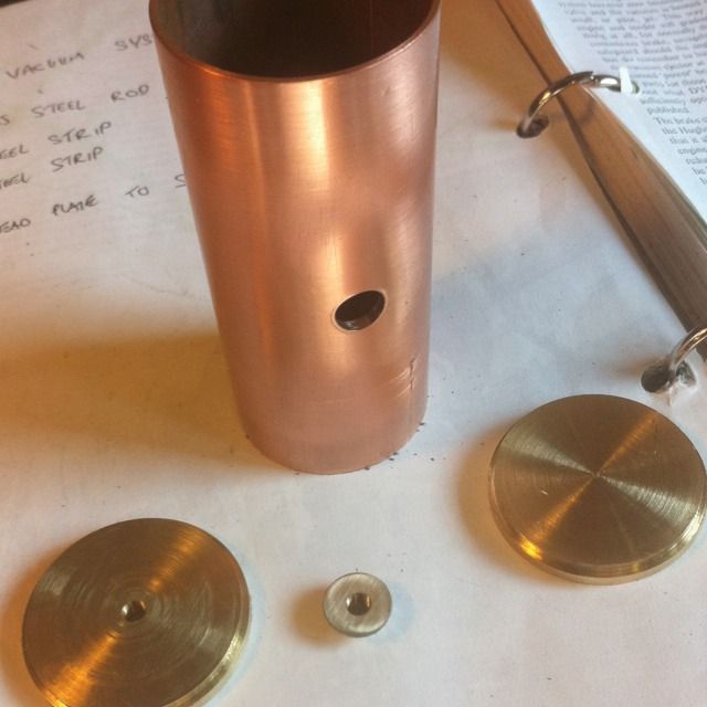
The vacuum brake reservoir stores enough vacuum to enable the brakes to operate, the brakes on this locomotive are the auto-brake system, that is, if the locomotive becomes separated from the tender the brakes are automatically applied. The reservoir tank is a simple thing to build, I have deviated from Don's drawing (I often do to make use of the materials at hand) and have machined up the ends from bar stock material and with a locating step for ease of manufacturer.
The picture shows the components made ready for making the tank. The 1 1/2" copper tube is to drawing, the end caps are supposed to be 3mm copper sheet of which I had none but I did have some brass billet left over from the filler neck so I made use of it. Rather than just turning up two plain 3mm discs I decided to include a 2mm step to be a tight fit inside the tube ends, one of which was centre drilled and tapped 3/16 x 40 T for the brake line. A small bush was also made , drilled and tapped 3/16 x 40 T for the drain plug, which fits into the hole seen in the tube center.
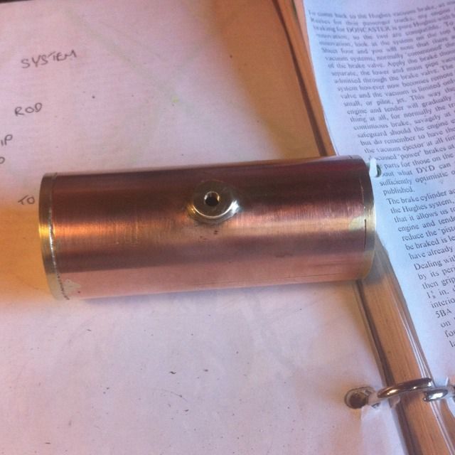
Here we have the finished tank after silver soldering together, now Dons words and music contradict themselves when it comes to pressure testing the vessel. The words say test to 100 psi, the drawing says test to 150psi so a little confusing although both seem a little high to my inexperience in such things.
I can't recall now which figure I tested it too, either pressure seems ok in my mind, anyway, it was tested and was leak free.
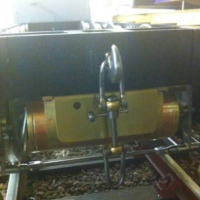
The tank itself is protected with a shield to stop the screw coupler from swinging down and damaging it. This was a simple item, 1/16 brass sheet, 2 1/2 long and 1 7/16 high with a 90 degree bend at the top. This has 5 No.44 holes drilled which are then transferred to the bottom of the drag box and then drilled/tapped 8 BA. Final thing was the 3/16 hole as seem for the rear vacuum pipe to pass through later.
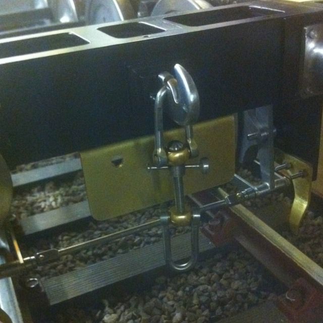
This underside view of the tender shows the tank now fitted.
Don listed 1.2mm thick 1/4 bands for this but I've used something a lot thinner, easier to form and nicer looking in my minds eye, more to scale. Because I've used such thin section the bent tab that's attached under the rear of the drag box I fabricated rather than just bending the band at 90 degrees, so here I've used 1.2mm brass that's been soldered to the end of each band and had a No.43 hole drilled in the middle. Two 1.8mm holes were then drilled at 2 11/16 centres and then tapped 8 BA for securing the bands. 4 pieces of 1/8 thick oak planks ( left overs from the tender planking) were then used as packing between the tank and drag box. Later these will be glued to the bottom of the drag box but that will have to wait until final assembly.
With the tank in situ the bands were pulled tight over and then marked for a slot to be drilled/filed , at the same time the drag box was marked, drilled and tapped 8 BA on it's front face to hold the bands via the slots. It's not that easy to describe but hopefully the picture helps.

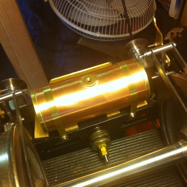
And a picture the right way up. Something that comes up here is whether I'll be able to get a fitting in between the tank and it's protector, there is some room but not much so I'll have to tackle that when I get to it.
It's important as I do plan on having a working vacuum conection here. If I do get around to making a full Flying Scotsman train ( which is the plan) I think I'll need working vacuum brakes throughout if hauling 12 coaches, " to much fun" as Jack would say...
NB: in regards to the last comment about room for a connection, I can confirm that all worked as planned and said fitting has been made and the vacuum pipework checked and it works very well, more on that later.