This was a fun thing to make, again it's fully functional and follows the same principles as the prototype. Of course it won't function exactly as full size as water doesn't scale but it will have water flowing through it as it should.
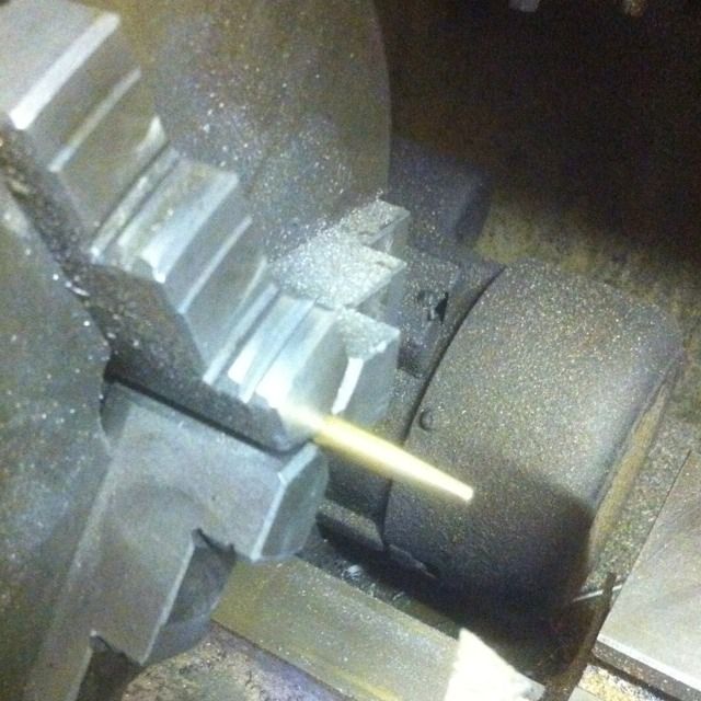
To start a length of 3/16 brass rod has a 4 degree taper turned over 1/2 length. With the topside still set at 4 degrees the brass is then replaced with 3/16 silver steel and the process is repeated, this will be used as a D cutter for forming the shape in the gauge block for the cone to fit.
Here the D bit is being formed by removing half of the silver steel cone, I did this in the mill as can be seen rather than filing as to Dons words. I take my hat off to anyone who can accurately file away half of a cone and get it 100% which a D bit has to be to work properly.
Next is the gauge block itself, 1/4 brass sq bar is chucked truly in the 4 jaw and once faced and centre drilled is turned down to 1/4 over a 7/32 length. The outer 1/8 is further reduced to accept a 1 BA thread to fit the water outlet in the tank ( should have been 3/16 x 40 T but I didn't have this tap when building the tank and since I wasn't going to use a commercial fitting here the thread wasn't important). A No.48 drill is then drilled to a depth of 7/32 , last job before parting at 1/2 overall is to machine a small v in the 1/4 section left between block and thread.
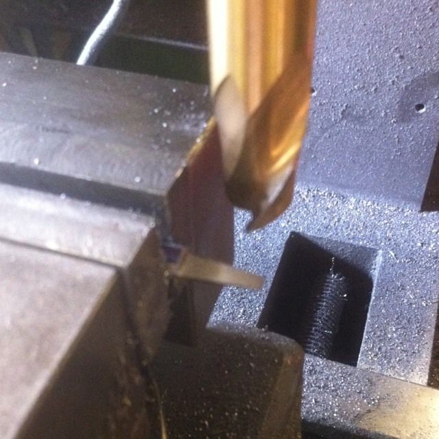
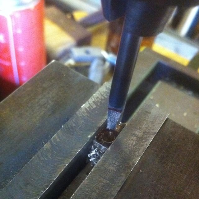
With the block placed into the machine vice a No. 38 hole was then drilled straight through the block at 90 degrees to the 1 BA thread and thus intersecting with the previously drilled No. 48 hole. Next, using the cone shaped D bit the cone was shaped until it measures 11/64 diameter at the top. BTW before I did this I first threaded the block into the tank tightly and marked the top so that the cone would be machined on the correct face for when fitted to the tender later.
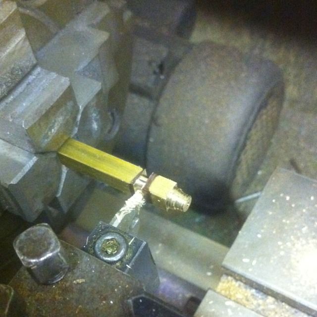
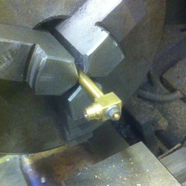
I then had to make sure that the cone was held securely and thus water tight when joined to the block so after refitting to the 3 jaw and securing the brass cone, the block was slid on and marked so that once the cone end had been turned down for its 8 BA thread it would hold the parts together in their correct positions. Here you can see the parts before parting off which is done allowing for 5/32 material for the measuring tube to fit into.
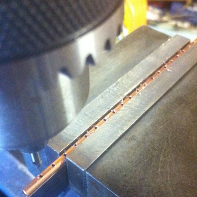
The measuring tube consists of a 6" length of 1/8 thin walled tube drilled at 1/4 intervals using a suitable centre drill, this is soldered to the cone having already been drilled No.30 for 1/8 for the tube to fit to and also further drilled 5/16 with No.48 that will intersect with the previously drilled holes that form the stop cock.
NB: the hole spacing was later changed to 1/2 intervals, I did this after looking more closely at my reference photos.
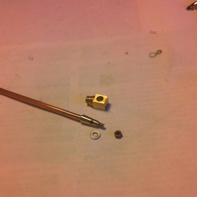
The various parts that make up the water gauge
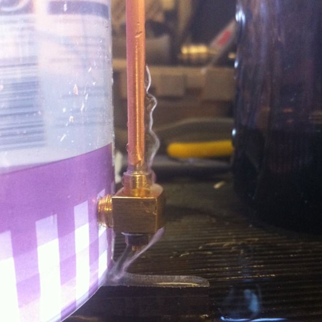
Before fitting I did a test to check all was ok, here you can see the water flowing through the holes once the cock had been opened which is a simple 90 degree turn operation. This was with the 1/4 spacing, the 1/2 should allow the water to go higher. I doubt that it will register the excat level in the tender as water doesn't scale, but it will work and will show that some water is in there, all for show of course...:)
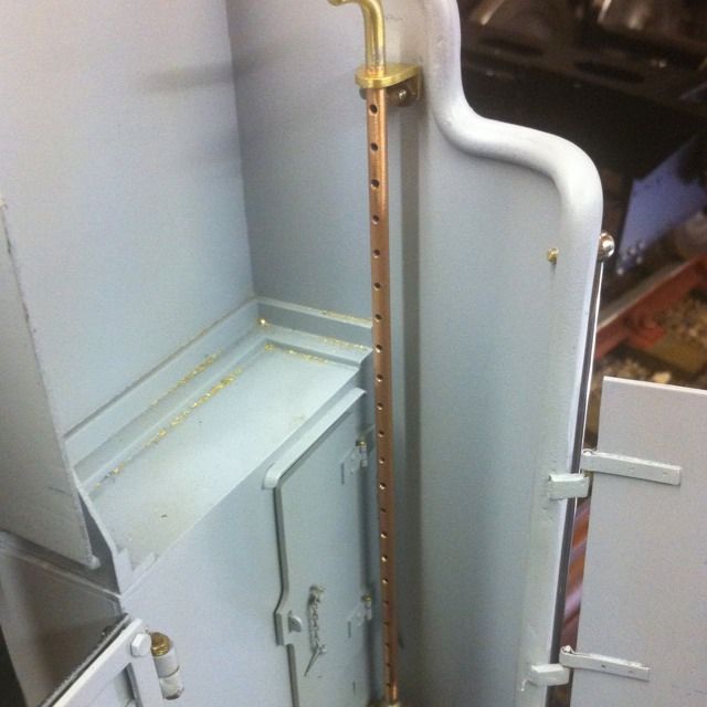
And here we have the water gauge fitted, other parts made are the bracket and the tube swan neck soldered to the top of the tube. The gauge is shown in it's closed position, to open the tube is turned 90 degrees to the front so that the holes face forward. Alas this is not a good picture as it's not showing the water valve itself, you will be able to see it in later photos though.
I have to admit to enjoying making this little thing, it was fun but more importantly was good practice for those small cones I'll be making when I tackle those important injector cones for the loco at some point in the future.
NB: I'll repeat that this picture shows the holes with 1/4 spacings.