
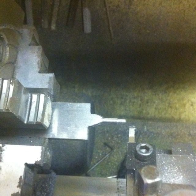
I started to follow Dons method for making the hook which basically starts off as a 4 1/2 x 1 x 3/16 flat BMS which you turn down in stages, the 3/16 dia shank first and then cutting away the access steel 3/4 at a time. As you can see in the picture I started this, chucked in the 4 jaw and turned down first the 9/64 x 7/32 spigot and then began turning the rest of the shank down to 3/16 ready for the spigot end to be threaded for 2BA over 9/16.
The job has to then be removed and the next 3/4 section has its access steel hack sawed off ready for round two. It was while I was trying to set the job true again ( I had already centred the spigot end to make it easier to realign) that it dawned on me that it would be far quicker to make this item in two pieces as I did with the spring hangers and silver solder together. So I cut the machined part off, realigned the job ( same as before as its offset) in the 4 jaw, faced and centre drilled ready for the shank once done.
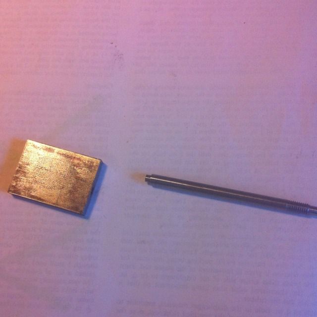
Her the individual parts are seen ready for silver soldering, the hook piece is 1 3/8 long and the shank is 2 13/16 plus the 3 mm spigot to fit the hook.
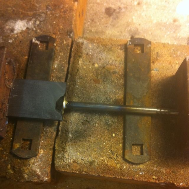
The parts now brazed together, now some may say a single piece would be stronger, perhaps if the joint was weak but with good penetration it should be as strong if not stronger. However Don states that Doncaster being a very powerful loco and able to haul large loads a more suitable arrangement should be used rather than the hook and coupling shackles , which is normal practice anyway. So this will only be for display purposes and I'll use a clevis type for actual running.
Next job was the two No.30 holes at 3/16 and 1/2 from the back of the hook on the shank center line. The inner hole then has a 5/64 slot machined up at 90 degrees to the shank. I didn't have this size slot drill but did have a 2mm which is only 0.02 mm bigger so this I used. The slot was chain drilled first.
Next up was to shape the hook, there are 3 main rads involved here so I cut templates out of some brass shim first. I then plotted the rad positions from the drawing which is drawn twice model size. Here you can see the templates and that the hook shape has been ascribed onto the hook blank.
The hook is seen here having been been roughly shaped to the lines using the band sander, now ready for the sides to be shaped next.
The finished hook, the end profile is basically a taper from the 3/16 at the bottom to just over 1 mm at the top and then everything is rounded off to finish. Thanks to a fellow ME I have very good pictures of Mallards hook so could use that as a guide. Oh on a side note, while looking through the pictures off Mallard, I noticed that she also has rectangular shock absorbers for the loco and thus different to the tender like 4472.
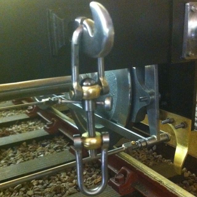
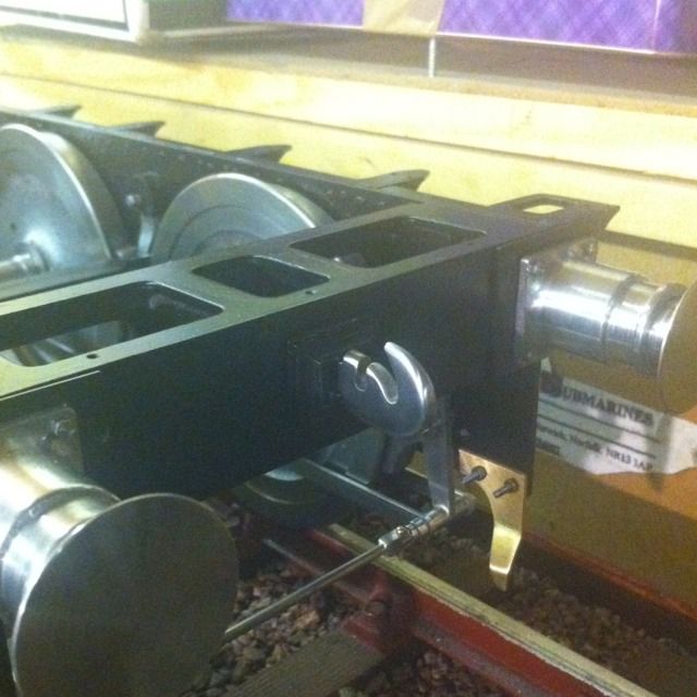
The finished hook looking great (even if i say so myself) in its rightful place.
Screw Coupler:
Don starts with the screw first ( forgot to take picture) which starts off with 1/4 BMS bar, reduced to 9/64 over 1 9/32 length screwing the end 4 BA thread for 29/32. Leaving 5/64 for rounding, it was then parted , reversed in the jaws and rounded off as to drawing.
Next was the shackle pins, Don's words and music started with two rectangular pieces of 9/16 x 3/8 steel , turning 1/8 spigots, mill top and bottom faces,turn the spherical center radius, finish with files, drill both and tap one off. That's one way, I had another..
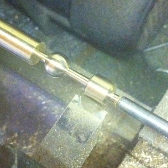
Using brass( remembering these are not for operational use) (NB: I may change this at a later late) I first faced ,center drilled and then turned down some stock to 3/16 rad allowing enough for both shackles and an extra length for the next stage. I turned down the 1/8 spigots remembering to leave enough space for parting later. I then made a profile tool following which worked out very well. In the picture you can see that one shackle pin has been done and the tool is lined up for the next. Note that I've stopped short of machining the full radius thus leaving a short flat area, this is for two reasons, first the radius is spherical ( finishing later with sanding sponge) and second I needed the pins to remain the same size dia as the stock for the next planned stage. NB: this was a nerve racking stage taking small cuts with constant checks on the tailstock as even using a live centre the brass centre hole did wear a little.
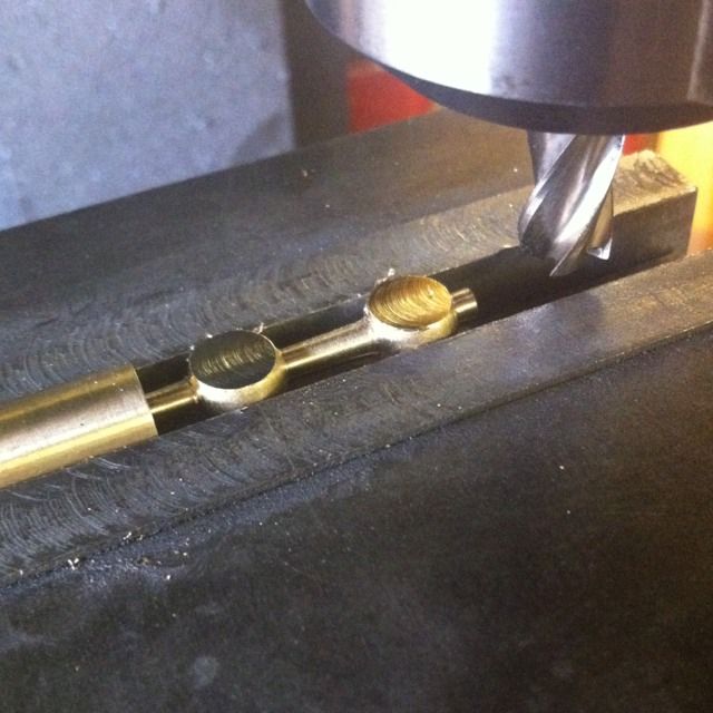
I then machined the top and bottom flats, this is the reason for leaving the small flat area at 3/16 so that the job could be held securely in the machine vice.
3/32 was then machined of both the top and bottom faces, both pins where then center drilled , one at No.27, the other at No.34 and then tapped 4 BA, final job was to saw off the shackle pins and file down the spigots to 1/8 length.
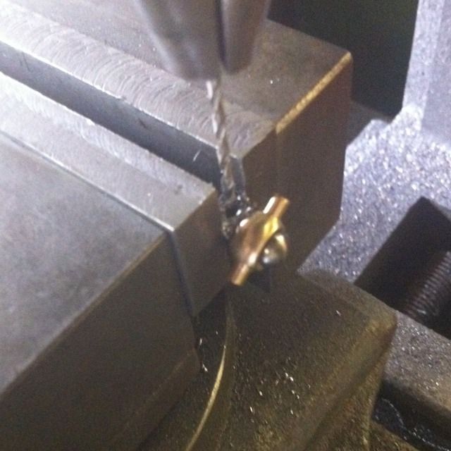
There's a No.50 cross drilled hole for the handle, first job was to turn up the collar which is 1/4 dia by 3/16 and center drilled No.28 for the screw. This was then cross drilled No.50 first before inserting the screw with the top pin slid on first so to get the hole in it's correct position which was then drilled as shown using the previous collar hole as a guide.
The handle is a 3/4 length of 1/16 steel which has a rounded 1/8 one end and 1/4 ( personally this looks a little large but is to drawing) the other. This was silver soldered together once placed in the collar, also seen here are the two ends for the shackles themselves before being silver soldered to the shackle bends and sawn/ filed to shape.
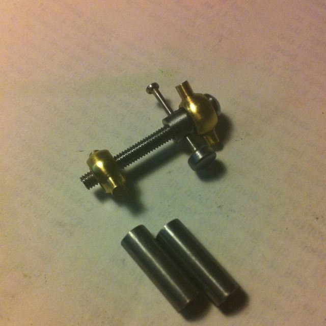
The finished coupling/hook , One other thing to note is the small flat area just visible on the top shackle which is for slipping the shackle through the 2 mm slot, feeding around and thus trapped within the hole.
