There are in fact 32 shock absorbers on Gresley's Pacific and I guess I should have built them all at once. However on further reading about FS it's come to light that the loco shocks ( except the trailing bogie) have a different shape to the tender, basically rectangular rather than oval so I left those till later, there's also the fact that I just didn't have the energy to do 32 at the same time, my poor fingers are getting very sore.
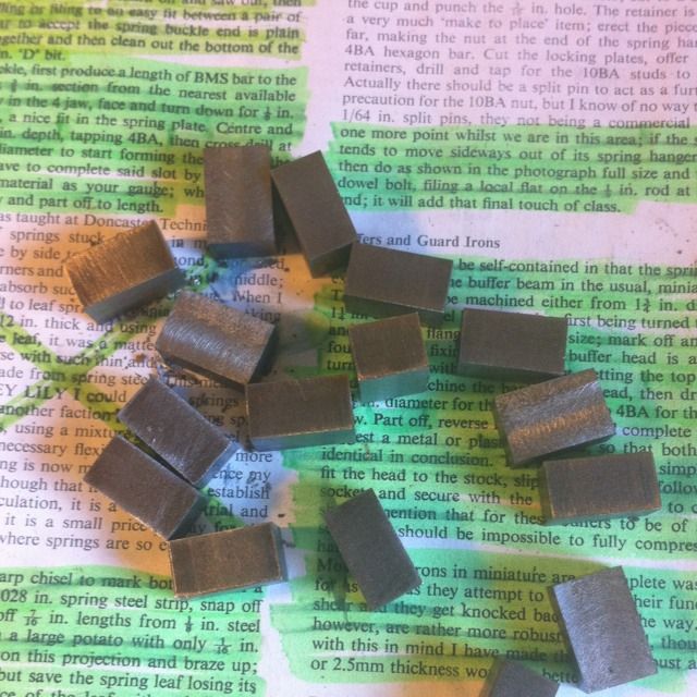
Here are the 16 rectangles cut and machined ready for shaping, size is 3/4 x 1/2 x 13/32 from BMS.
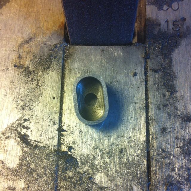
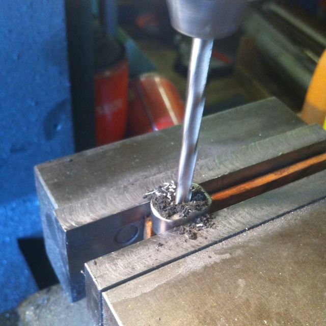
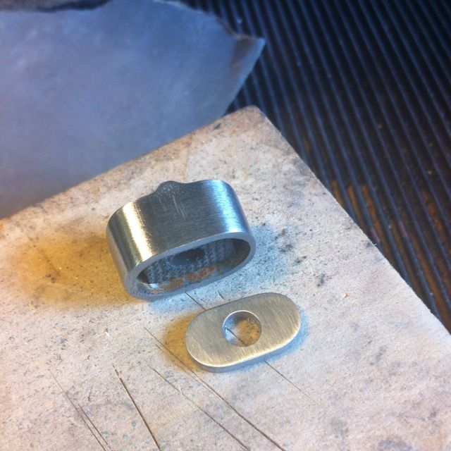
With the shocks marked out ( easier to do before drilling the hole) they were then drilled in the centre of the 3/4 x 1/2 face using a No.10 drill.
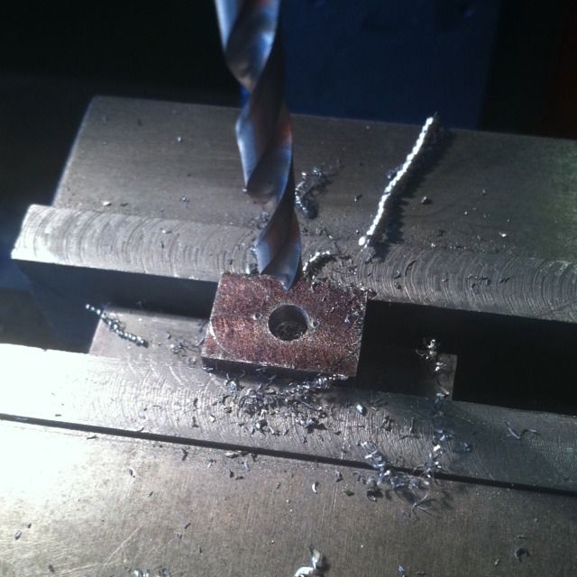
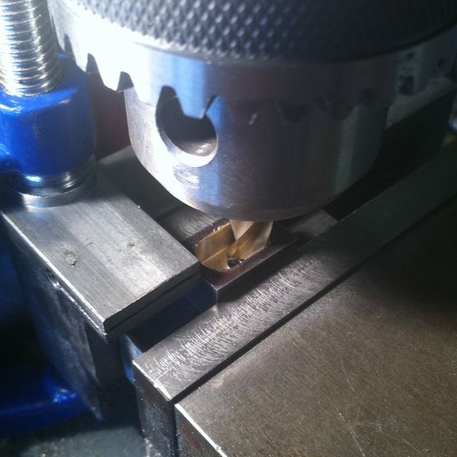
Next job was to mill out the recess for the rubber to sit into, This needed a 11/32 end mill, yeh right??? So I used a smaller one first ( only had a plain shank of the required size hence why I'm using a drill chuck) (NB: I had no Collett chuck in those days) and then finished with the correct sized slot drill using a proper Clarkson auto-lock chuck.
It was then time to tackle the shape, here you can see the top template cut from brass sheet and the shocks lined up having already had the required shape ascribed on to their sides. The top has to be done first as I need a flat service for each stage and wouldn't have this due to the 5 degree taper on sides and ends.
The top now roughly shaped using the band sander, this was later finished off using files and sanding pads
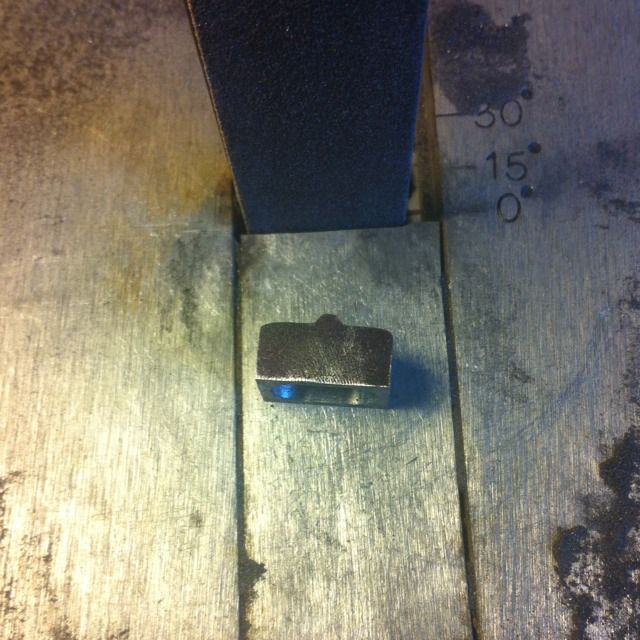
As mentioned the ends and sides have a 5 degree taper so the sander table is set at the correct angle for this and shaping begins.
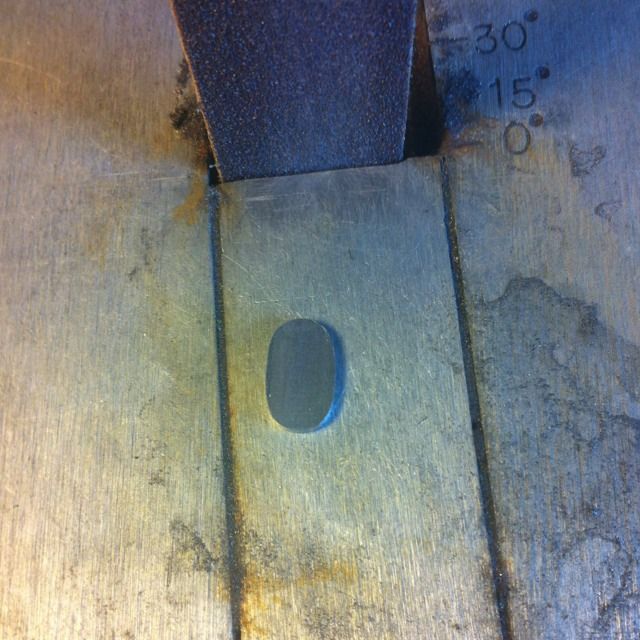
Since the top isn't flat a template couldn't be used but here the earlier recess comes in handy as it was a simple task to keep checking underneath to unsure the correct shape was being made as shown here.
Next was the retaining plates, again these were shaped using the sander first and filed to finish..
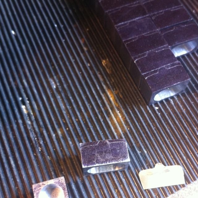
Don says to use 3/16 rubber sheet or smaller if not available, all I have is the ribbed matting that I use on the the bench as you can see in this picture so I cut some of this up and put the ribbed faces together that is then close to 3/16, worked a treat.
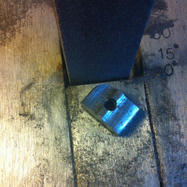
Now the rubber and retaining plates needed the No.10 hole drilled for the spring hanger and to me the easiest way of doing this was to assemble the parts first and then drill using the existing hole as a guide for position.
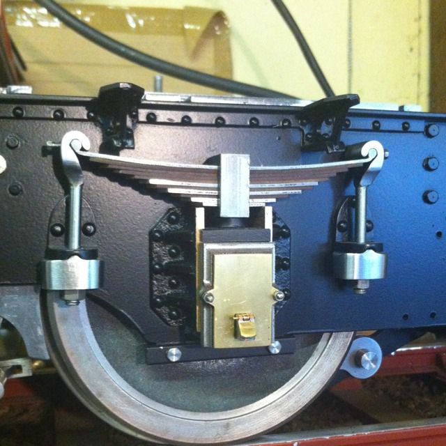
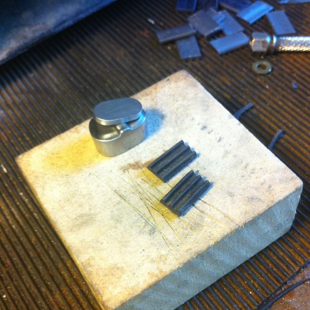
The shock absorber so far , you can just see the rubber inside the recess.
The parts were then assembled and fitted to the chassis, there is a further job to do on the retaining plates which involves some 10BA studding and some lock plates to be made. A job I'm ashamed to admit that i still haven't got around to doing, those who have been following me for some time now will know just how often i say.. 'a job to be added to that very long list of things to do'...well this is one of them:)

All shocks now fitted, I had only fitted them loosely in this picture as everything needed taking apart later for painting.
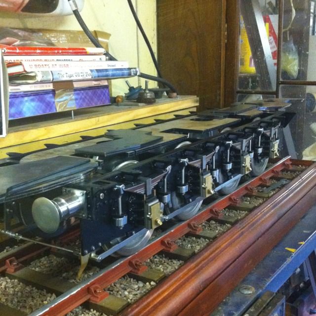
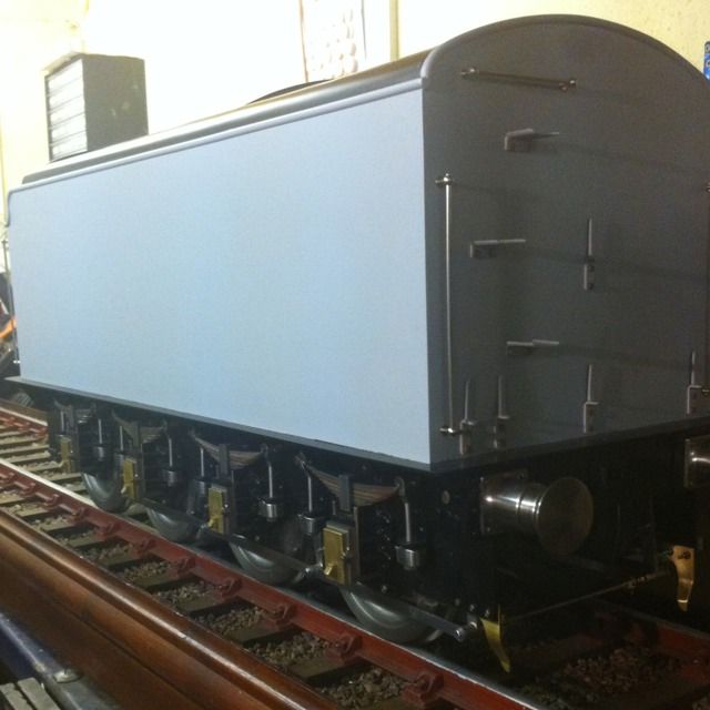
Final picture for this session showing the body sitting on top of it's now fully sprung chassis.