Ok, so we now move onto both the spring hanger and brake hanger brackets. The brakes and suspension components will be filling these blog pages on and off for a while, there's a lot to them.
First the spring hanger brackets, these are simple items made from right angle steel, drilled and filed to shape. There are 16 for the tender and 4 for the loco, I decided to do all of them together as it's easier, I also did a few spares just in case.
First I made a jig for both drilling and filing, this started as 1"x1"x1/8th steel right angle which was drilled and then filed to shape. This was then heat treated to dull red , dipped in oil and left to cool , polished, heated again to a yellow colour for tempering and left to cool at room temperature.
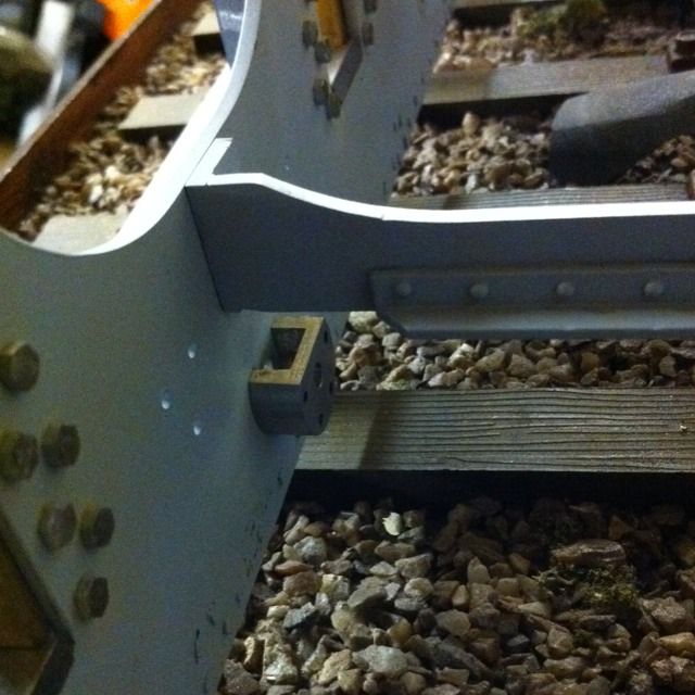
Here is the finished pattern test fitted to the frames to check all is well. The pattern is oversized, to allow the correct size right angle to fit inside it, of course the pattern had to be machined in it's corner to square it up to allow this.
First job was to machine some right angle down to 3/4x9/16th, I had nothing close to this so had to use the same material that was used for the jig. I machined two lengths both of 8" length to this size, I then machined the corner to both make it was square ( steel right angle tapers from middle to edge) and reduce the thickness from 1/8th to 3mm as to drawing.
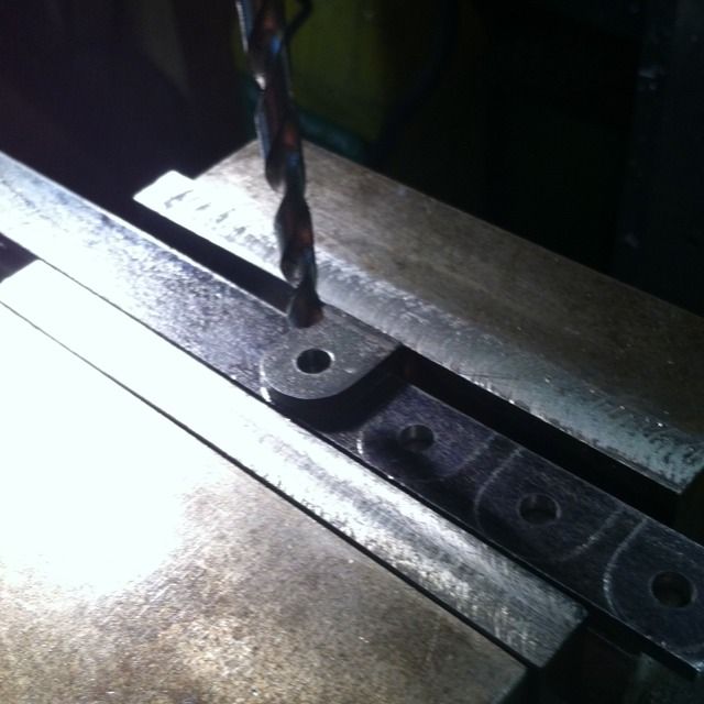
With this done the pattern was held in the machine vice with the angle trapped to it. The three 1/8th holes taken from the drawings where drilled first and the outline was scribed, this was done 11 times along both sections of angle thus giving me 22 brackets.
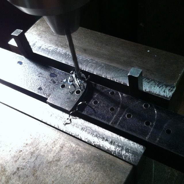
With the frame holes drilled and the shape marked the angle was then turned over for the other face to be drilled and ascribed. Here the No.22 hole for the spring hangers is being drilled , to ensure this was inline with the 3 holes on the other face the pattern was located in place using 3 x 1/8th rivets and again held tight in the machine vice.
Before separating the brackets I needed to machine a slot across the No.22 hole with a 3/16th ball nose cutter for locating the shock absorber. This you'll see later in this update as I had to order a suitable cutter and wait for its arrival.
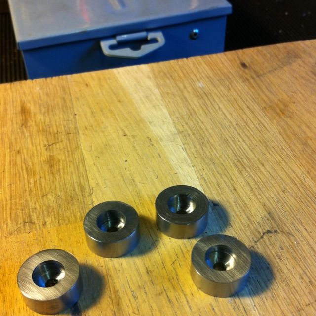
Whilst waiting for the ball nose I moved on to the brake hanger brackets. There are two types , these four are the middle and rear hangers. First a length of 3/4 steel was held in the 3 jaw and turned down to 21/32 . This was centered and drilled No.22, Don says to make a D bit and machine a 3/8 recess to a depth of 5/16. I decided to forgo that and use a 3/8 slot drill in the tailstock, it just means I have to accurately measure the 5/16 depth for each one. So the order of things was, No.22 hole, 3/8 recess to 5/16 and then part off at 7/16. This was done 4 times as shown in the picture.
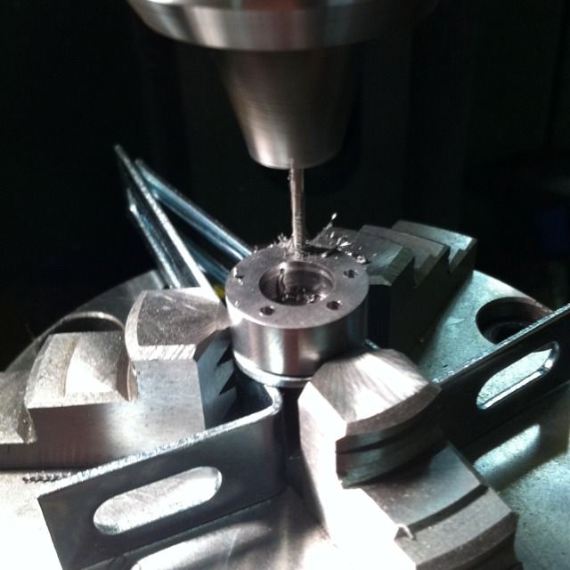
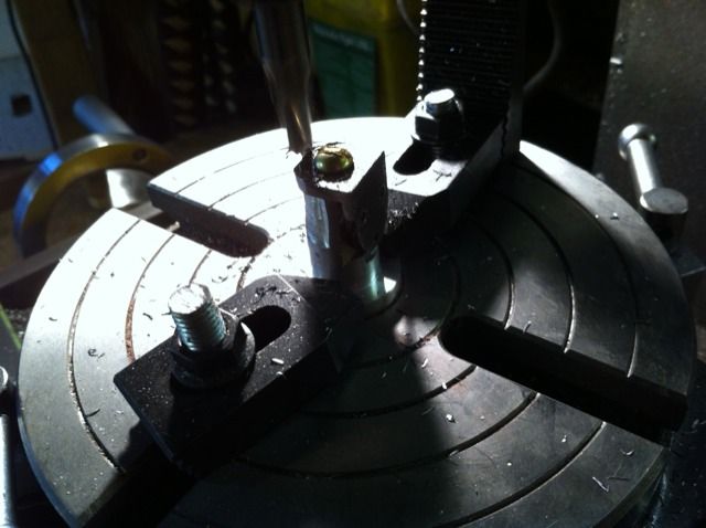
The last job for these was to drill the 4 holes to attach to the frames, these were done on the rotary table at 255,330,30,105 degrees as to drawing.
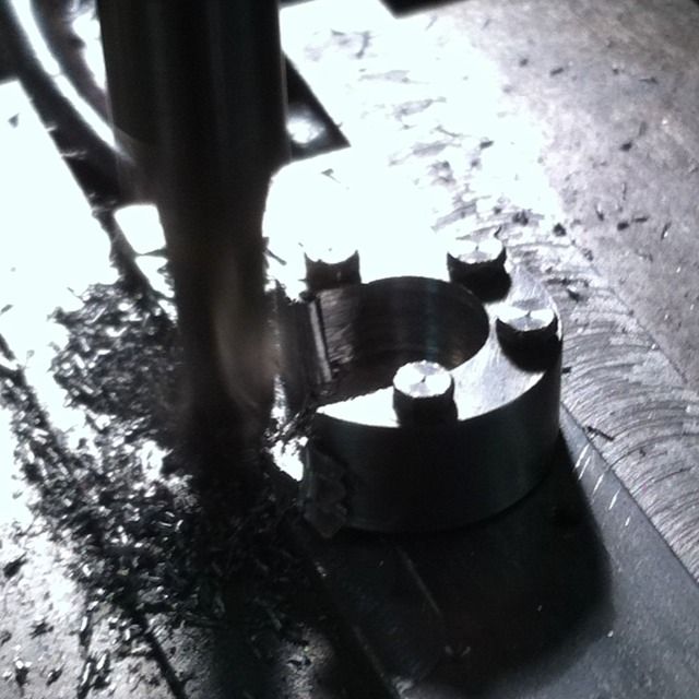
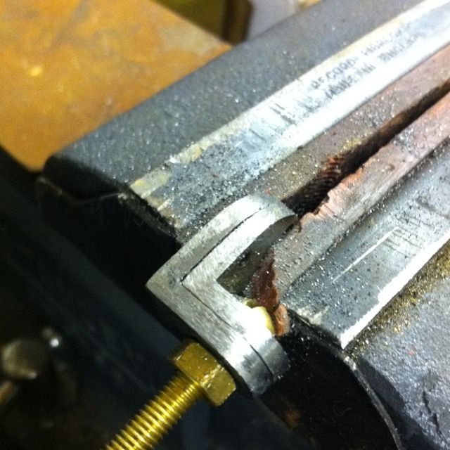
To finish the machining of the brake hanger brackets I transferred the 4 holes to a piece of flat steel, drilled and tapped for 8BA. With the bracket thus held I could finish the 3/8 recess cutting directly out from the centre. The final operation was to cut the flat section at 90 degrees to the recess 5/16 from centre, as shown in the picture.
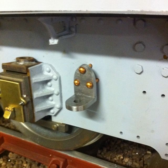
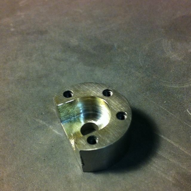
The finished item ready to be fixed to the frames. The holes have been drilled and tapped for 8BA bolts.
Each bracket was then held in place using a nut and bolt, squared to frame and the holes were transferred using a transfer punch. Bracket was then removed, holes drilled and each bracket was then attached to the back of frames as shown in the picture.
Here the rotary table is being used to shape the bottom curve of the bracket. I turned up some alloy bar to an MT2 taper to fit the table with a spigot that has been drilled and tapped 2BA to hold the bracket. To stop the bracket from turning on the spigot the back edge was machined flat. The other face has already been roughly ground to shape ready to be fixed back to the jig for final filing.
Returning to the spring hanger brackets these were fixed in turn to the hardened jig and held in the vice for filing.
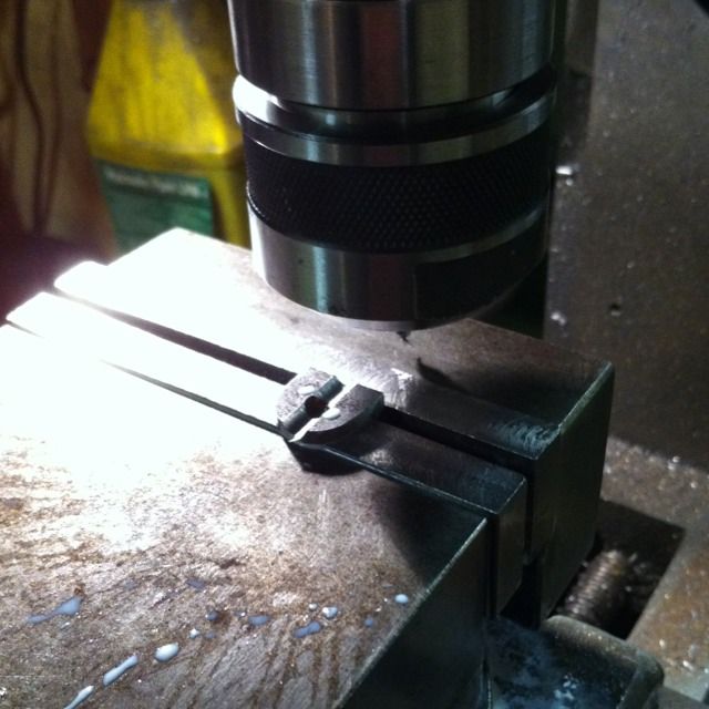
Now that the 3/16 ball nose cutter had arrived I could get on with the final machining operation to the spring brackets which was to cut the shock absorber locating slot using the 3/16 ball nose slot drill as shown here.
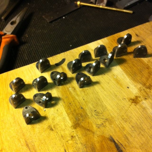
Here we have all 16 spring hanger brackets ready for riveting to the frames.