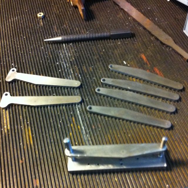
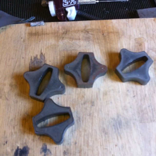
These are the brake hangers, they are laser cut items from Model Engineers Laser. There are 8 in total, 2 front which are the ones with the boot leg shape at one end, 4 intermediates and 2 for the rear. In the foreground is a jig made to ensure that they all have 2 3/4" centres between the hanger pin and control rods. There will be another hole about one third up from the control rod pin hole to fix the brake shoes too later.
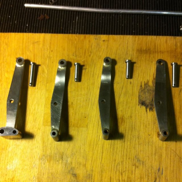
The 2 rear hangers are seen held on the jig awaiting the bossed ends to be brazed on once machined. The intermediates have to be bent a little as shown on the drawings, these need to be longer to allow for the two bends as all have the same centres of 2 3/4". For some reason they were all supplied the same length, this was no big deal as I intended to machine the bosses as one piece and cut a slot to slip over the end of the hanger. To allow for this I cut off the end if each hanger half way through the hole, with the bosses brazed on they look complete and using the jig I was able to ensure that they all retained the 2 3/4 centers.
The advantage of using aser cut parts is you can make a lot of progress, we can all saw/file out metal sheet, but why when you can put that time into super detailing the model instead, well at least that's how I see it..:)
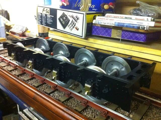
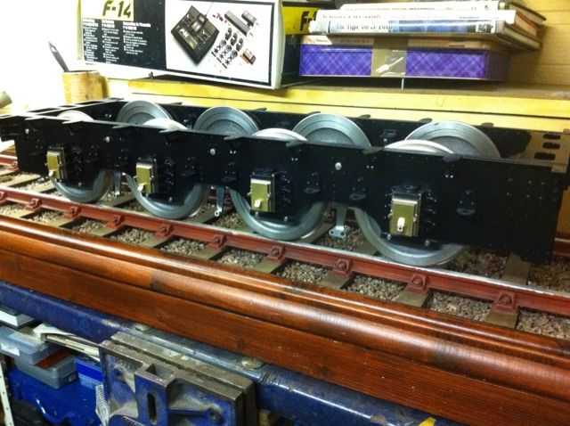
All brake hanger brackets were then fixed to the frames with 8BA small sized hex heads. The frames were then given a number satin black base coats and left to fully cure before painting the vermilion lining.
It was probably at this point that I began to realise just how much work was involved in building an 8 wheeled monster tender like this. The brakes were a very time consuming job which involved making many small items. I now understood most of what was involved in the brakes for the tender although it would have been helpful if Don had included a plan view of the tender brake layout as he has for the engine itself.
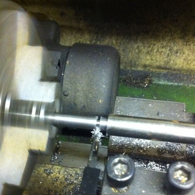
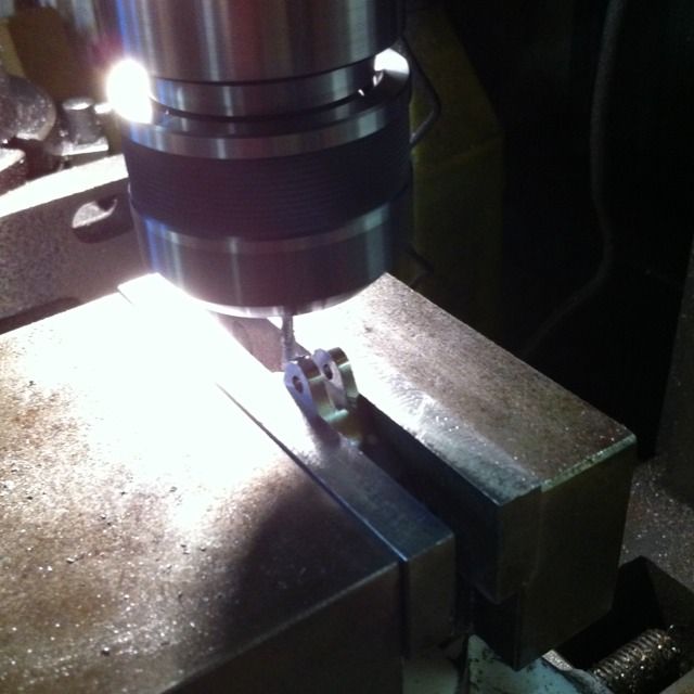
Their are two size diameters of end bosses, 1/4" and 5/32", these are center drilled and then drilled No.22 and No.30 to match the hanger holes. They vary in length but the picture shows the 1/4" dia BMS being parted of at 1/4" length. A piece of 1/2 steel was held in the tailstock as a stop to measure each 1/4" section.
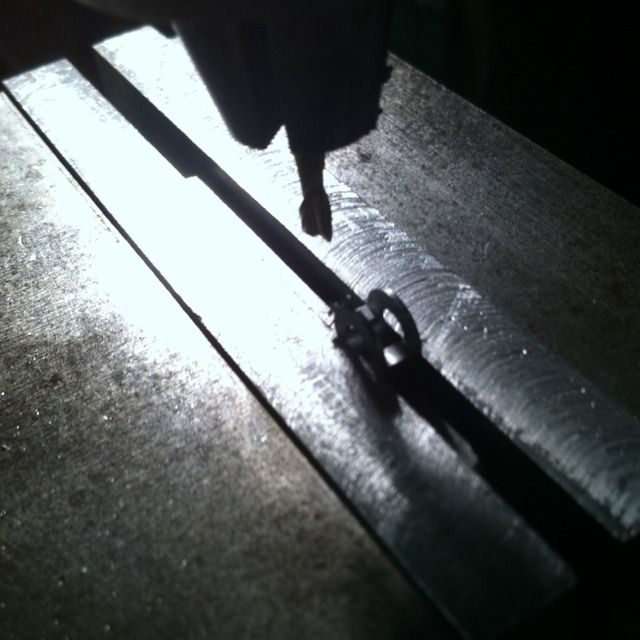
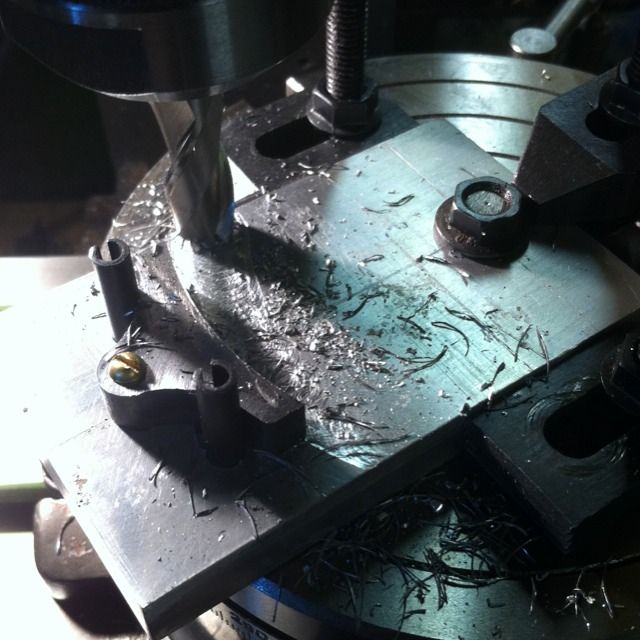
Here the same 1/4" section is now having a 3mm slot cut for the hanger to fit into ready for brazing.
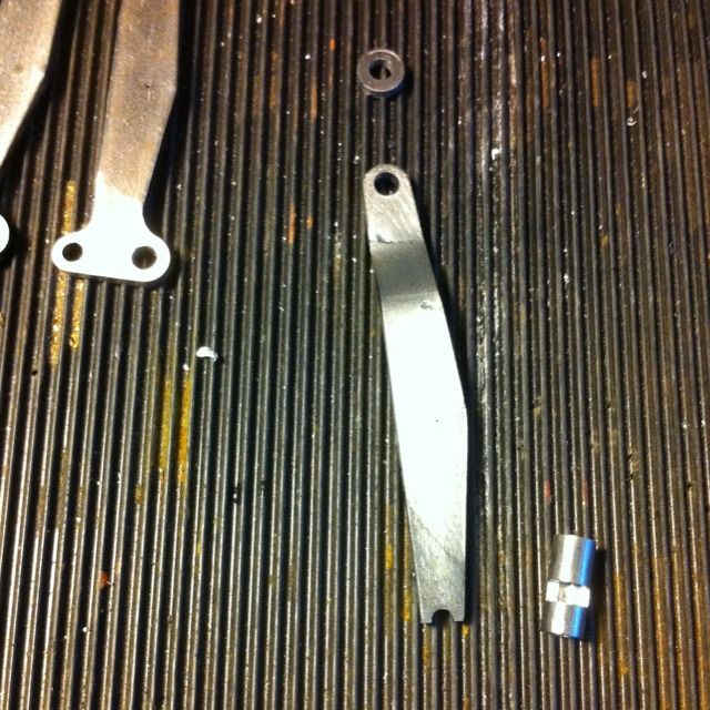
The intermediate hangers have an offset angle as shown here, they have a small boss on one side at the top so no need to cut a slot for this one. The bottom does need a slot which is offset at 9/32 on the inboard side for wheel clearance. Here the parts are ready for brazing.
Here are the completed hangers and pins for one side. The pins are 5/32 steel with 1/4 x 1/16 collars brazed on as suggested by Don, made sense as it was quicker to make. The pins are also cross drilled to take a 1/16 split pin.
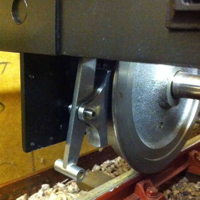
Brake hangers fitted, the front hanger has two bottom holes, one (large) is for the front brake beam the second being for the first control rods.
Close up of the front hangers.
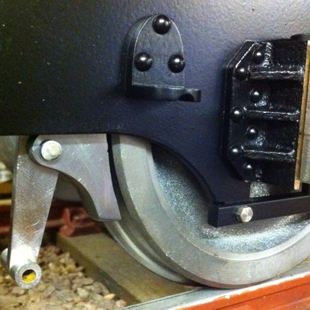
And here's a close up of rear hanger
It was then time to tackle the brake shoes, in the picture are the laser cut shoes from Model engineers laser , having now machined these I think it may have been quicker to machine from solid. Being such thick material the laser had hardened the edges deeply and cut at a slight angle in places plus the material was thicker than the drawing do had to be machined to size. They also needed making symmetrical too. Still I persevered and battled on
Here is the jig I made/used for holding each shoe while it's inner face was machined to 2 7/32 R. The pin hole has already been drilled to No.30 and used to help hold the shoe rigid between the two 5mm roller pins. As I post this update which is 10 years old now and I am currently doing the loco brake shows this image is very helpful, the loco shoes came as a ring but having now machined those to size, I think that I may need to use the jig seen here (slight mod for the rad) to take some more metal off, they match the drawing for distance from pin to outer edge but that seems a little 'off' to me.
Next stage was to mill the slot that slides over the brake hanger and then held via the pin. The pins were made the same way as the larger hanger pins.
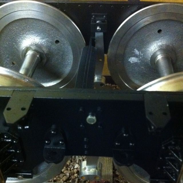
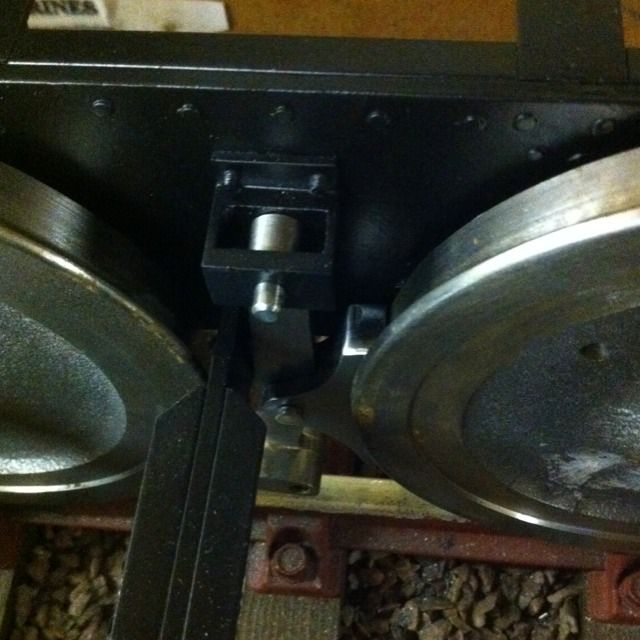
View showing the inside of the brake assembly for the front axle
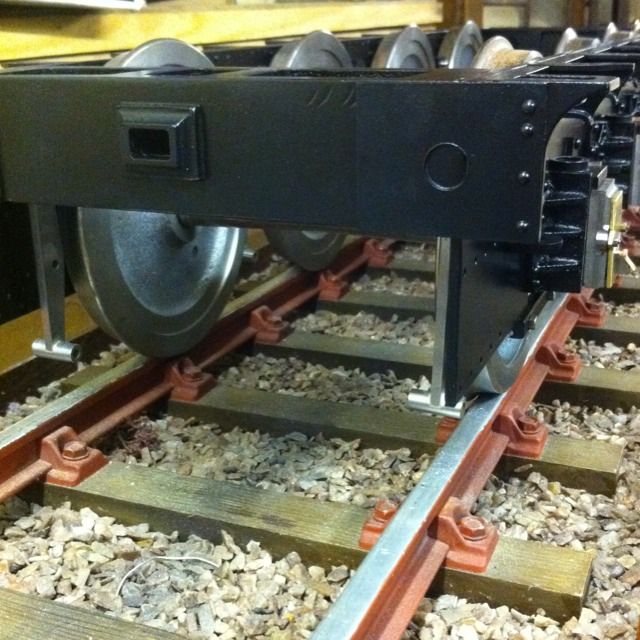
Outside view showing brake assembly for the second axle

this last picture shows inside view of the rear axle. I can confirm that there is indeed an error for the third brake hanger as has been mentioned by others regarding "drawing errors" before me. It's nothing big just needs some metal removing from the back edge of that particular brake hanger to allow enough clearance for the shoe to fit between the hanger and wheel without fouling against the rear stay.