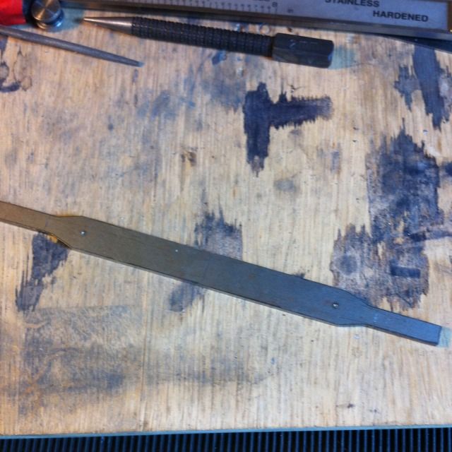
Continuing with the brakes here we have the last laser cut part from Malcolm's brake hanger kit. This is the front brake beam, if you look closely you'll spot the ascribed lines across the end tabs. I decided to remove these and turn up the required 5/32 diameter spigots separately and silver solder them on .
To replace the removed tabs I first turned up the two parts needed. These started as 1/4" BMS bar of which the beam has a 1/16 collar between the beam plate and the 5/32 coupling rod shaft. Since I planned to cut a 1/8th slot through the 1/4" section I increased it's depth to 1/4" to give more area for brazing and thus stronger, I doubt anyone would notice but if they do, hey who's loco is it anyway:)
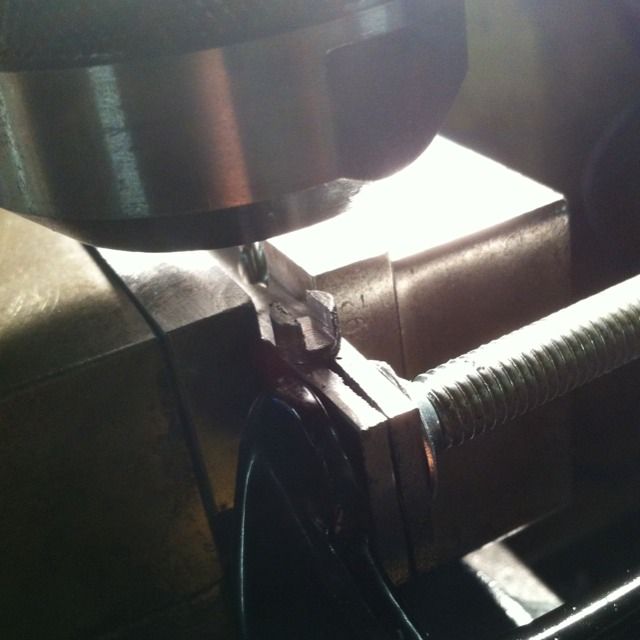
In the picture the finished shaft is seen being held in a jig for machining, using a suitable piece of BMS I drilled a No.22 hole for the 5/32 shaft the fit into. Having cut a slot in the end of the BMS it was easy two hold the shaft both tight and upright for machining.
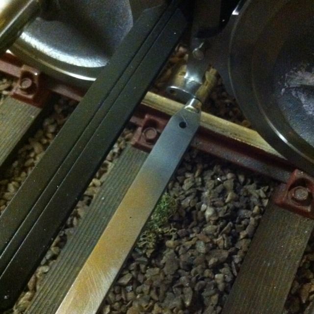
I forgot to take a picture of the parts before brazing but here is the finished beam now fitted. Its had both the two No.30 holes drilled for the connecting rods to the brake shaft and the also been cross drilled for 1/16th split pins.
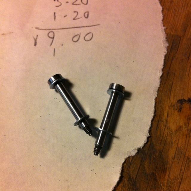
The two coupling rod pins for the front axle were a similar exercise to the brake shoe pins but have 7BA threaded ends and a small 1/16 spigot on the end. The washers are commercial items, about time I found something already made to use , so much time spent making things with little to show for it.
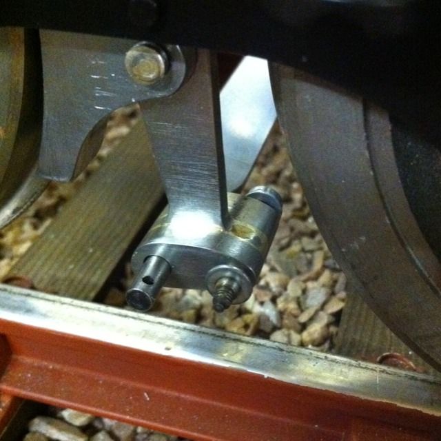
Here we see the front brake beam and pin in place, at this stage I still needed to make the nuts for the pins. I did those in a batch together later.
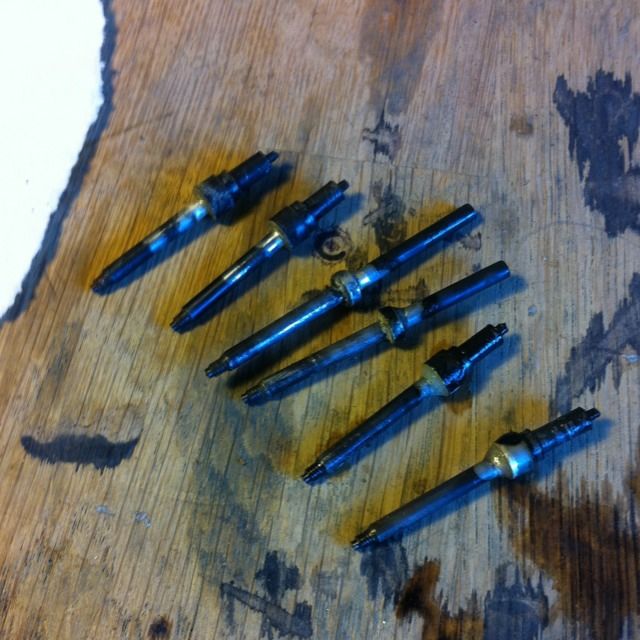
JNext job was the brake pins and beams, these are the pin components having been silver soldered together before final machining and polishing.
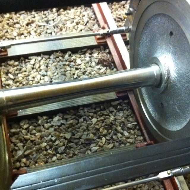
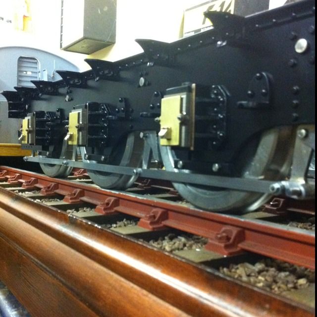
The third and fourth axles brake beams/pins fitted.
Close up of the fourth axle brake beam. The beams are made up from three parts, two ends with the slots and the central BMS bar that fitted into predrilled holes in the end pieces. A jig was made up with 4" centres to hold the parts together for brazing.
I then turned my attention to the brake coupling rods, nothing much to these other than lengths of 1/4 x 1/16 BMS bar , machined to profile and with a No.30 hole drilled each end and then rounded off.
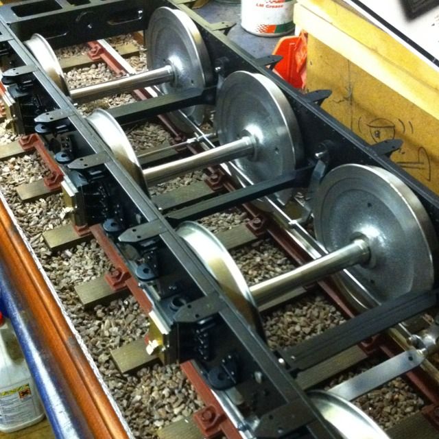
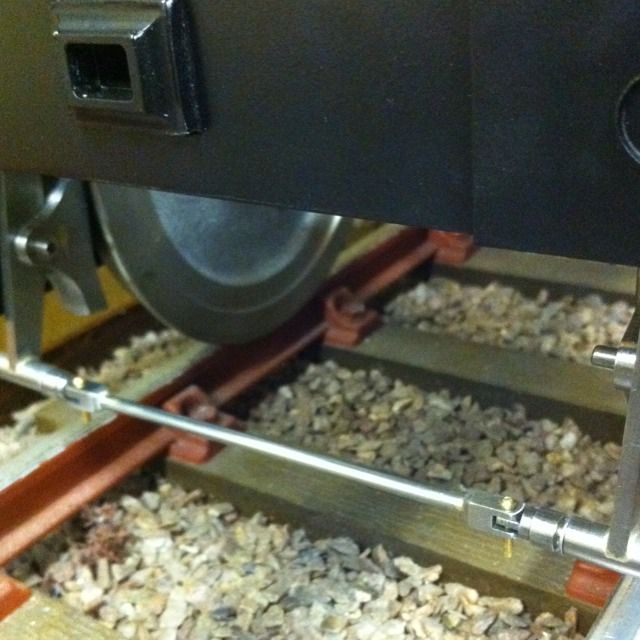
The distance between the holes is critical and the chassis needs to be at it's right height before measuring the distance between pins. So first the chassis was raised on blocks to achieve this, next all brake blocks were clamped tightly against the wheels. It was then a simple job of measuring each distance between the pins and then making the coupling rods up as pairs to fit. here we can see the coupling rods fitted .
And now a top view, washers are used to achieve the necessary clearance from the wheels as to Don's words and music. I was pleased with the end result, all four wheels locked when the front brake beam was pulled which boded well for the brakes working as they were supposed too later.