Today I have details of the brake shaft construction, this one item took me two days. So much work for a relatively small yet important part of the tenders braking system.
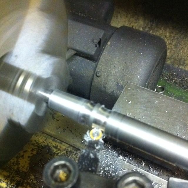
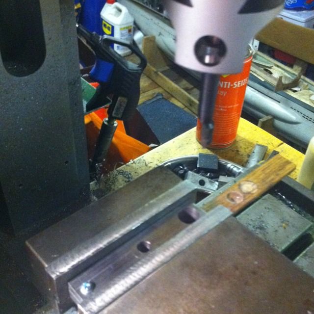
The picture shows the start of machining on the shaft itself. It starts life as a 6" piece of 1/2" BMS ( centre drilled) which has a 1/4 diameter spigot to 5/16 depth machined on both ends. With the top slide then set at 4 degrees a section was machined to 7/16 up to the first collar( using a round nose tool) the first collar is 3/32 at 1/2 diameter . A cut is then made back to 7/16 for 5/32, leave another collar at 1/2 for 3/32 and back down to 7/16 until reaching the first brake leg collar. A 1/4 section is left here then back at 1/2 and then the tool cuts again at 7/16 for the middle section. The shaft is then reversed in the jaws and the process repeated for the other side. Hope that's clear, took me a while to work it out and Don described it better than I. To explain a little the four 3/32 collars are for the small brackets that attach to the front pull rods, the 1/4 sections are for the two large legs that attach to both the handbrake system and the two vacuum cylinders.
There, crystal clear...:)
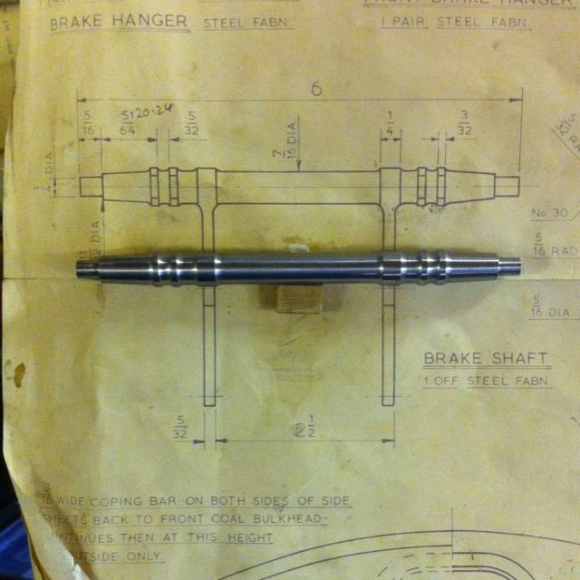
The turning part completed shown against the drawing. Lots of work but worth the effort.
Next up was the legs, here we have the two legs being drilled together before profiling.
Once profiled to shape the next stage was to reduce the width except for the part that meets the shaft. The tongue at the far end was be removed once finished.
On to the small pull rod brackets, holes drilled first as with the legs and then held together for machining. The alloy bush is just there to hold inline as once finished the tongue was also be removed as with the legs.

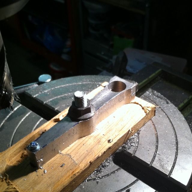
On to the first brazing stage, I began with the small brackets seen held together with 1/8 BMS that has had a 5BA thread cut to unable a holding jig to be made ready for silver soldering to the shaft.
With the brackets attached it was on to the legs using a similar holding jig prior to also being silver soldered in place, remembering to fix at 90 degrees to the rod brackets.

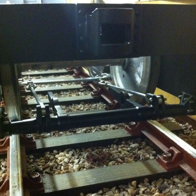
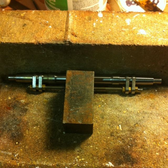
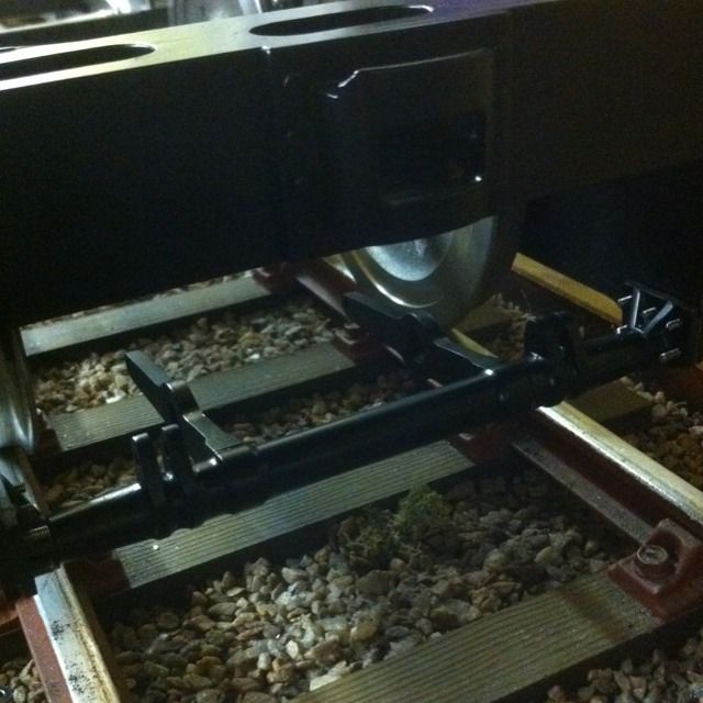
The finished brake shaft placed loosely between the frames awaiting the support brackets that will hold it.
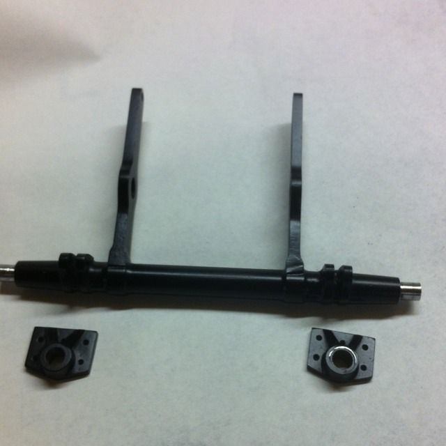
Here we see the finished brake shaft and trunnion parts ready for fitting to the frames. The trunnions were pretty straight forward affairs, consisting of 1/8 steel plate cut to size and shaped. Next, 7/16 BMS bar collars were machined to size and bored out to 1/4 to accept the 1/4 spigots on the brake shaft, these were then brazed to the plates. The final jobs being the four small webs that were first cut oversize, soft soldered in place and then ground down to their final shape leaving just the mounting holes that were transferred from the frames, these were drilled and then tapped 8BA.
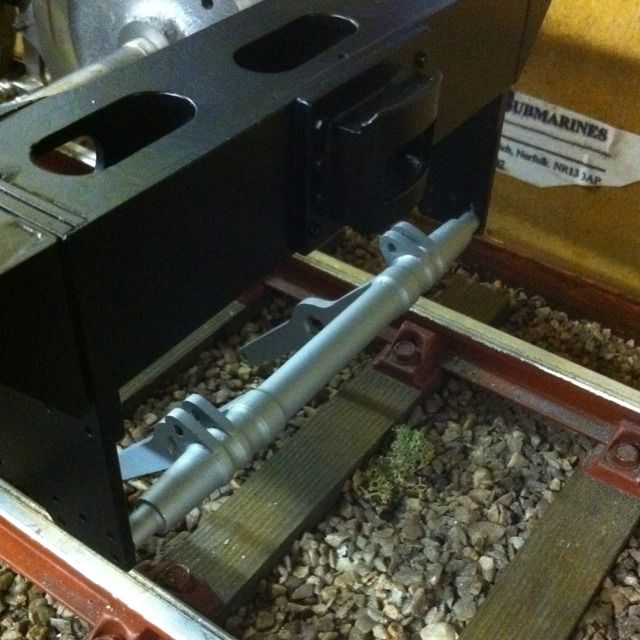
The shaft tried in place, beginning to look the part.
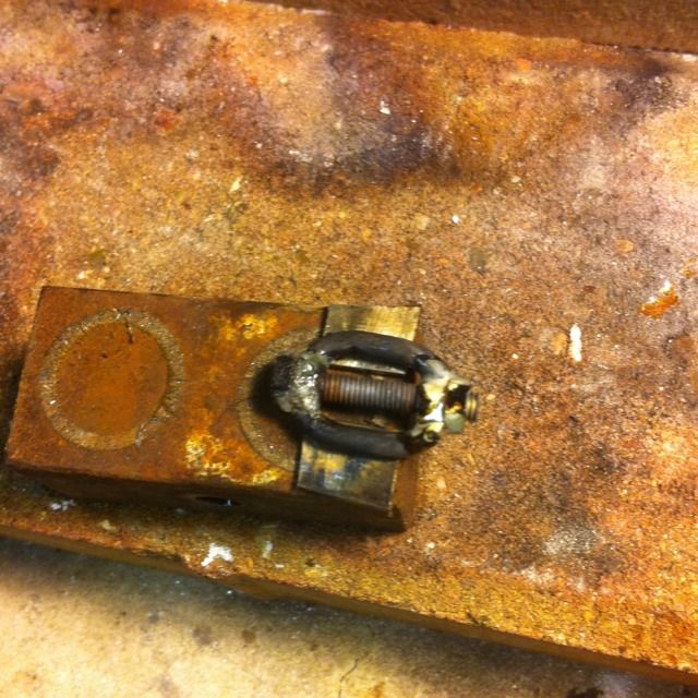
Here under the burnt flux is one of the adjusting nuts. On the prototype these have opposite threads at each end but as Don states in his words there's no need for it here and since I haven't got a left hand thread 5/32 x 40 T tap/die I went with him. BTW Don actually suggested 5/32 x 32 but I didn't have this size at the time so went with the 40 T, but hey just means I have a finer adjustment..
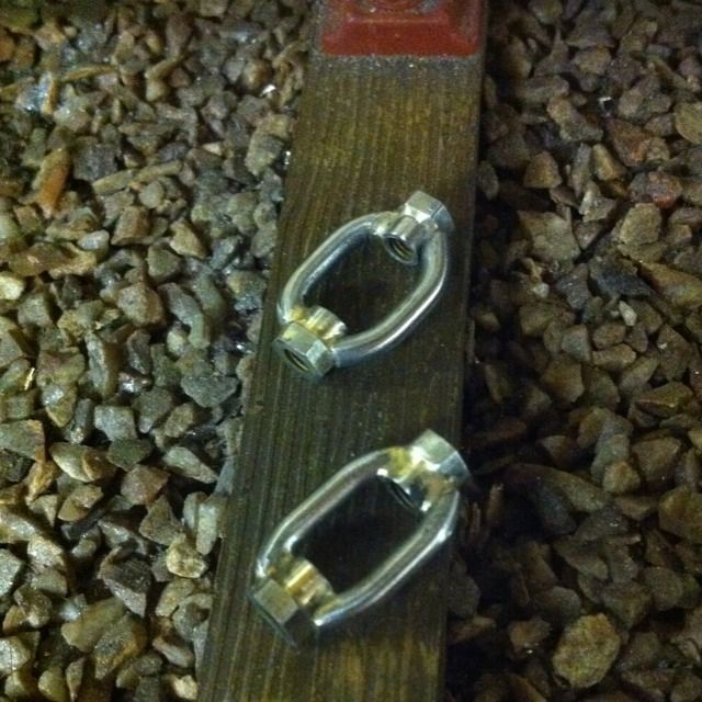
The two finished adjusters after being acid dipped to remove the flux. These were involved little buggers, first 1/4 hex bar has a spigot turned on it and bored out to accept a 5/32 x 40 T tap which was then parted at 1/4 length. Using some threaded rod to fit, a nut is screwed on each end with the spigot facing inward to an overall length of 15/16.
Next was the fun bit ( I think not) 1/8 bar is bent to shape with a 3/8 middle section and a shallow bend either side, the ends are then scalloped to fit the profile of the spigots. After covering the lengths of studding with soap the parts were held together with magnets and brazed up. The soap did it's job and the studding was easily removed to leave the final items as shown.
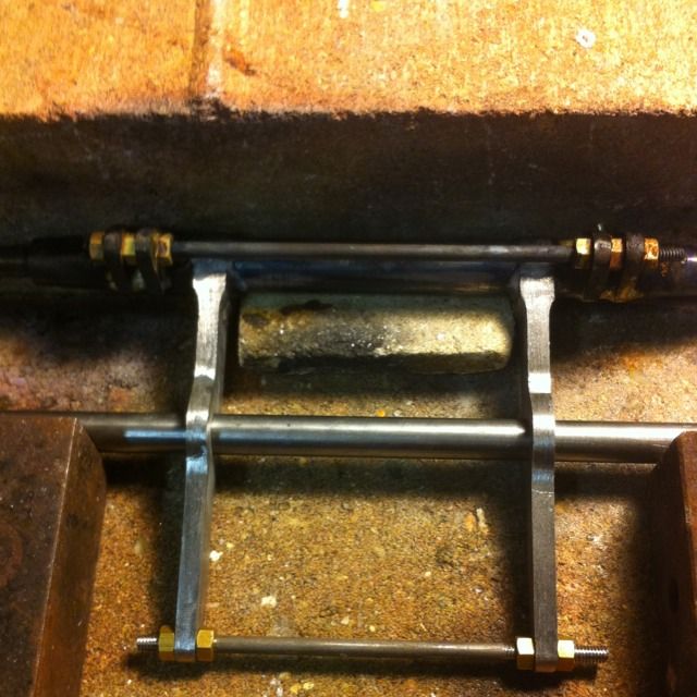
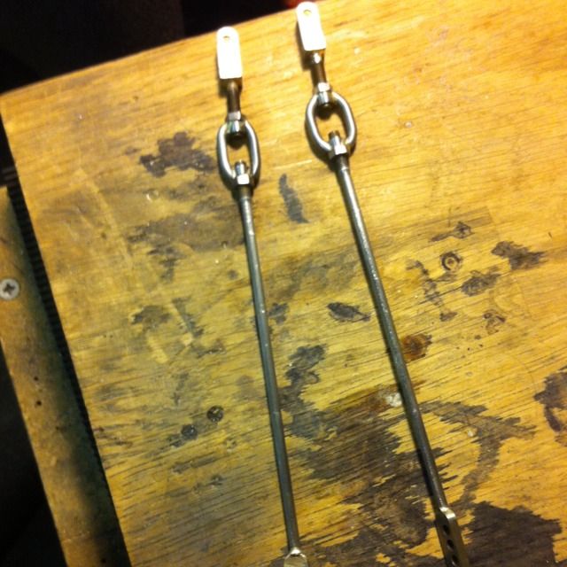
Here are the finished adjusters and rods ready for fitting. The other parts are similar to the parts already described so I haven't gone over their construction again.
A picture to show the parts fitted, here's a view from the front